1
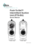
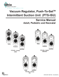
Push-To-SetTM
Continuous Vacuum
Regulators (PTS-CVR)
Service Manual
MAX
MAX
MAX
F
H
F
H
M
M
L
L
MEDICAL VACUUM
F
H
F
H
M
M
L
L
MEDICAL VACUUM
2 Mode
3 Mode
User Responsibility
IMPORTANT: Federal law in the U.S.A. and Canada restricts
this device for sale by or on the order of a license medical
practitioner.
WARNING: This device is to be used only by
persons who have been adequately instructed in its
use.
WARNING: Do not use this device in the presence
of flammable anesthetics. Static charges may not
dissipate and a possible explosion hazard exists in
the presence of these agents.
This Product will perform in conformity with the description
thereof contained in this operating manual and accompanying
labels and/or inserts, when assembled, operated, maintained
and repaired in accordance with the instructions provided.
This Product must be checked periodically. A defective
product should not be used. Parts that are broken, missing,
plainly worn, distorted or contaminated should be replaced
immediately. Should such repair or replacement become
necessary, see the Ohio Medical service manual for service
or repairs to this product. For service advice, Ohio Medical
recommends that a telephone request be made to the nearest
Ohio Medical Regional Service Center. This product or any
of its parts should not be repaired other than in accordance
with written instructions provided by Ohio Medical or by Ohio
Medical trained personnel. The Product must not be altered
without the prior written approval of Ohio Medical’s Quality
Assurance Department. The user of this Product shall have
the sole responsibility for any malfunction which results from
improper use, faulty maintenance, improper repair, damage,
or alteration by anyone other than Ohio Medical.
Product Date Coding:
AAA A 12345
This alpha character indicates the year of product
manufacture and when the serial number was assigned;
“L” = 2007, “M” = 2008, “N” = 2009, etc. “I” and “O” are not
used.
Technical Competence
The procedures described in this service manual should be
performed by competent individuals who have a general
knowledge of and experience with devices of this nature.
No repairs should ever be undertaken or attempted by anyone not having such qualifications.
Read completely through each step in every procedure
before starting the procedure; any exceptions may result
in a failure to properly and safely complete the attempted
procedure.
Genuine replacement parts manufactured or sold by Ohio
Medical must be used for all repairs.
8700-0006-000 Rev.3
2
Table of Contents
1/Precautions
1.1 Definitions ................................................................ 1
1.2 Warnings .................................................................. 2
1.3 Cautions ................................................................... 2
2/Scope
2.1 North American Vacuum Regulators. ....................... 2
2.2 International Vacuum Regulators ............................. 2
3/Description and Specifications
3.1 Description................................................................ 3
3.2 Specifications ........................................................... 4
4/Operation
4.1 Equipment Set-up ..................................................... 5
4.2 Attaching the Safety Trap ......................................... 5
4.3 Mode Selection ......................................................... 6
4.4 Setting the Suction Level .......................................... 6
4.5 Pre-Use Checkout Procedure................................... 6
4.6 Patient Set-up ........................................................... 8
5/Cleaning and Sterilization
5.1 Cleaning ................................................................... 9
5.1.1 Routine Exterior Cleaning...................................... 9
5.1.2 Internal Component Cleaning ................................ 9
5.1.3 Cold Flush Procedures .......................................... 9
5.1.4 Disinfecting ............................................................ 9
5.2Sterilization ................................................................ 9
6/Troubleshooting ..........................................................11
7/Service - Disassembly and Assembly
7.1 Service Tools and Equipment ................................. 13
7.2 Continuous Vacuum Regulators (All Models) ......... 13
7.2.1 Disassembly ........................................................ 13
7.2.2 Assembly ............................................................. 13
7.3 Suction Level Limit Setting - Low Models ONLY .... 14
7.3.1 Low Vacuum Limiting Screws .............................. 14
7.3.2 Vacuum Relief Valve Adjustment ......................... 14
7.4 Regulator Module ................................................... 14
7.4.1 Disassembly ........................................................ 14
7.4.2 Assembly ............................................................. 14
7.5 Digital gauge........................................................... 15
7.5.1 Removal of batteries............................................ 15
7.5.2 Inserting Batteries................................................ 15
3
8/Service Checkout Procedure
8.1 Set-up................................................................... 16
8.2 Flow Test ................................................................ 16
8.3 Gauge Test ............................................................. 16
8.3.1 High Vacuum Gauges ONLY ............................... 16
8.3.2 Standard and Low Vacuum
Gauges ONLY ........................................................... 16
8.4 Regulation Test ....................................................... 16
8.5 Low Vacuum Regulators ONLY .............................. 16
8.6 Bleed Test ............................................................... 16
8.7 Leak Test - Supply Side .......................................... 16
8.8 Leak Test - Patient Side.......................................... 16
9/Maintenance
9.1 General Maintenance of Suction Equipment .......... 17
9.2 Recommended Maintenance Schedule.................. 17
9.2.1 Maintenance Schedule ........................................ 17
9.3 Repair Policy .......................................................... 18
9.4Technical Assistance ............................................... 18
9.5 Return Instructions ................................................. 18
9.6 Warranty................................................................. 19
9.7 Installation Procedure for Adapters/Probes
and Fittings ............................................................ 19
10/Ordering Information
10.1 Illustrated Parts..................................................... 20
10.2 Service Kits........................................................... 20
10.3 Fittings and Adapters ............................................ 20
10.4 North American ..................................................... 20
10.4.1 Regulator Options.............................................. 20
10.4.2 Other Options .................................................... 20
10.5 International .......................................................... 20
10.5.1 Regulator Options.............................................. 20
10.5.2 Other Options .................................................... 20
8700-0006-000 Rev.3
1/Precautions
Definitions
Note:
A Note provides additional information to clarify a point in the text.
Important:
An Important statement is similar to a note but of greater emphasis.
CAUTION:
A CAUTION statement is used when the possibility of damage to the equipment exists.
WARNING:
A WARNING statement is used when the possibility of injury to the patient or the operator exists.
MAX
= maximum
High Flow
High Vacuum
= high flow, high vacuum
High Flow
Low Vacuum
= high flow, low vacuum
I (On)
= on
O (Off)
= off
Abbreviations Used In This Manual
CCW
CVR
MAX
in Hg
kPa
LPM
mm Hg
°C
°F
N-m
ft-lb
oz
DISS
OES
NCG
NPT
NPTF
MPTS
gal
PTFE
PTS
1
Counterclockwise (Anti-clockwise)
Continuous Vacuum Regulator
Full Line Vacuum
Inches of mercury
Kilo pascals (kPa x 7.50 = mm Hg)
Liters per minute
Millimeters of mercury (mm Hg x .133 = kPa)
Degrees Celsius
Degrees Fahrenheit
Newton-Meter (N-m x .737 = ft-lb)
Foot-Pound Force (ft-lb x 1.356 = N-m)
Ounces
Diameter Index Safety System
Oxequip Suction
National Compressed Gases (Chemetron)
National Pipe Thread (USA)
National Pipe Thread Female (USA)
Multi-Purpose Therapy Stand
Gallon
Teflon®
Push-To-SetTM
8700-0006-000 Rev.3
1/Precautions
1.2 Warnings
After patient use, regulators may be contaminated. Handle
in accordance with your hospital’s infection control policy.
2/Scope
This service manual contains service, maintenance and parts
information on all models of the Push-To-SetTM Continuous
Vacuum Regulator.
North American
Clean and sterilize all suction equipment before shipment
or service to ensure transportation personnel and/or service
personnel are not exposed to any hazardous contamination.
Connect the Vacuum Regulator to the vacuum source only and
check its operation before attaching the patient connection.
Connection to pressure sources even momentarily could
injure the patient or operator and damage the equipment.
International
2.1
North American (ANSI) Vacuum
Regulators
Note:
Part numbers given are for PTS-CVR without
fittings or adapters.
Do not use this device in the presence of flammable
anesthetics. Static charges may not dissipate and a possible
explosion hazard exists in the presence of these agents.
If the Vacuum regulator is repaired or disassembled in any
manner, the Service Checkout Procedure must be performed
before using the equipment on a patient.
1.3 Cautions
Do not lubricate any internal components of the regulator
module.
Do not use any Loctite® products to seal the fitting and
adapter port threads (or products which contain Methacrylate
Ester as an active ingredient).
Only competent individuals trained in the repair of this
equipment should attempt to service it.
To help prevent aspirate from entering the regulator, as a
result of misuse, an Overflow Safety Trap and suction filter
should be attached prior to its use. Aspirate in the regulator
will impair the operation. The use of the Overflow Safety
Trap and suction filter will help prevent this and extend the
life of the suction equipment.
Use of lubricants other than recommended may degrade
plastic or rubber components.
Prior to placing the unit back into service after repair or
disassembly, perform the Service Check-out Procedure.
Not for Field or Transport use**
®Loctite is a registered trademark of the Loctite Corp.
** The categories of Field and Transport Use are specifically defined in ISO
10079-3. “Field” means use at accidents or emergencies outside a hospital.
“Transport” means use in ambulances, cards and airplanes. These situations
may expose the equipment to uneven support, water, dirt mechanical shock and
temperature extremes. Ohio Medical suction equipment has not been tested to
comply with the specific requirements of these categories.
8700-0006-000 Rev.3
2
3/Specifications
3.1 Description
WARNING Do not use this device in the presence
of flammable anesthetics. Static charges may
not dissipate and a possible explosion hazard
exists in the presence of these agents.
The PTS-CVR is a lightweight, compact unit used throughout
the hospital primarily for pharyngeal/tracheal suctioning
(airway management). Various models provide regulated or
full-line vacuum for hospital suction procedures.
There are several models of the PTS-CVR. All models
contain a vacuum gauge which indicates suction supplied
by the regulator. Each has a positive pressure safety relief
valve to prevent pressurization by either failed injector
vacuum (venturi) units or inadvertent cross connection to
pressurized gasses. In addition, the Low PTS-CVR models
include a vacuum relief valve to limit maximum suction.
Some models operate in a regulated or non-regulated (MAX)
mode. Others operate only in the regulated (limited) mode.
In the non-regulated (MAX) mode, the vacuum source is
connected directly to the fitting port. The regulator module is
bypassed and full-line vacuum is provided.
In the regulated (limited) mode, the vacuum source is
connected through the regulator module which functions as
an automatic valve. Turning the suction control knob adjusts
the position of the regulator module and allows selection
of a predetermined level of suction when set according to
instructions.
During use, as the flow requirement increases, the valve
automatically opens to maintain suction at the preset level.
Conversely, when the flow requirement decreases, the valve
automatically closes to maintain suction at the preset level.
The same mechanism compensates for changes in supply
vacuum and automatically maintains the pre-set suction
level when set according to instructions.
1. Suction Control Knob - Allows easy adjustment of
suction to the patient.
2. Mode Selector Switch - Allows quick and easy mode
changes.
a. | (On) - Suction can be adjusted with the suction
control knob.
b. O (Off) - No suction is supplied to the patient.
c. MAX - Maximum full-line vacuum is supplied to the
patient.
3. Vacuum Gauge - The suction level to the patient is
displayed during use.
Mode
Selector
Switch
MAX
Vacuum
Gauge
Adapter
Port
Suction
Control
Knob
Fitting Port
3
8700-0006-000 Rev.3
3/Specifications
3.2 Specifications
Gauge:
Accuracy(Analog):
Accuracy(Digital):
±5% of full scale deflection
±1% of full range at 22oC
Flow Rate:
0 to 80 LPM without fittings at full increase setting depending on supply
vacuum and open air flow
Positive Pressure Safety
Relief Valve:
Located in the vacuum supply line to prevent pressurization of the
patient connection by failed injector vacuum (venturi) units, or inadvertent
cross connection to pressurized gases
Ranges:
Gauge Range
Regulated Suction
Standard Models
High Models
Low Models
0 to 200 mm Hg/0 to 26 kPa
0 to 760 mm Hg/0 to 100 kPa
0 to 160 mm Hg/0 to 21 kPa
0 to 760 mm Hg/0 to 100 kPa
0 to 760 mm Hg/0 to 100 kPa
0 to 135 mm Hg/0 to 18 kPa*
* When measured with an independent measuring device.
Vacuum Relief Valve
(Low Vacuum models ONLY):
140 mm Hg ± 5 mm Hg/18.7 kPa ± 0.7 kPa
Weight:
(Less fittings)
11 oz/312 grams
Weight
Low Vacuum models:
(Less fittings)
12 oz/340 grams
Dimensions:
(Less fittings)
Height: 5.7 inches/145 mm
Width: 3.0 inches/76 mm
Depth: 3.8 inches/96 mm
Latex tubing, 0.25 in (6.4 mm) I.D. X
12 in (30 cm) supplied:
0 to full vacuum
Flow dependent on source and setup
Disposable tubing (Available
separate in some markets;
6 mm I.D. X 450 mm, 750 mm
and 2M) to connect regulator
and collection bottle
0 to full vacuum
Flow dependent on source and setup
Disposable Suction Filter:
0 to full vacuum
0 to 100 Lpm @ 650 mmHg (-87 kPa)
Environmental Specifications
Operating Temperature Range:
Storage Temperature Range:
Operating and Storage Relative Humidity:
8700-0006-000 Rev.3
40oF (4oC) to 120oF (49oC)
0oF (-18oC) to 150oF (71oC)
5 to 95%
4
4/Operation
4.1 Equipment Set-up
Locking Gland Fitting
Insert the probe into the vacuum wall outlet. If the regulator
is mounted elsewhere, connect a vacuum supply hose
between the regulator’s probe adapter and the wall outlet.
1. Raise the sleeve and insert the trap into the regulator
fitting.
2. Turn the trap clockwise about one and a half turns
to engage the threads. The trap does not need to be
screwed tight; an O-ring in the regulator fitting provides
a vacuum seal. The trap should rotate freely to allow the
desired tubing positioning.
3. Lower sleeve to lock trap in position.
WARNING Connect the vacuum regulator to the
vacuum source only and check its operation
before attaching the patient connection.
Connection to pressure sources, even
momentarily, could injure the patient or operator
and damage the equipment.
Regulator
Note: For proper installation of Adapters/Probes and Fittings
see Appendix.
Connect the collection bottle’s vacuum port to the regulator’s
fitting port or Overflow Safety Trap with the appropriate
suction filter and vacuum tubing.
An Ohio Medical High Flow Suction Filter should be used
between the collection container and regulator to prevent
contamination of the regulator.
Use hospital-supplied suction tubing between the end piece
and the collection container, and between the patient port
and the patient (minimum inside diameter is 6 mm [0.25 in.]).
ISO 10079-3 (BS 7259: Part 2, section 5.1.2) states that “the
usable volume of the collection container shall not be less
than 500 ml.”
Suction Filters
Hydrophilic:
Pkg of 20
Pkg of 200
Nipple
6730-0350-800
6730-0351-800
DISS fitting
1. Insert trap into the regulator fitting. Situate the tubing in
the desired position.
2. Turn the DISS wing nut clockwise to engage threads and
tighten (there is no O-ring, so the vacuum seal depends
on a tight connection).
Hydrophobic:
Pkg of 3
Pkg of 10
Pkg of 100
Nipple
Threaded
6730-0570-800
6730-0580-800
6730-0571-800
6730-0581-800
6730-0572-900
6730-0582-800
Regulator
Wing Nut
4.2 Attaching the Overflow Protection Device
(OPD)
CAUTION: To help prevent aspirate from entering
the regulator, wall outlet and pipeline system as a
result of misuse, an Overflow Safety Trap should be
attached prior to its use. Aspirate in the regulator,
wall outlet and pipeline system may impair their
operation. The use of the Overflow Safety Trap and
suction filter will help prevent this and extend the life
of suction equipment.
5
8700-0006-000 Rev.3
4/Operation
4.3 Mode Selection
4.4 Setting the Suction Level
| (On) - Suction can be adjusted with the suction control
knob.
1. Turn the mode selector switch to I
(On).
2. Occlude or clamp tubing
3. Rotate the suction control knob until
the vacuum gauge indicates the
required setting.
2-Mode Switch
MAX
WARNING The regulator fitting
port or patient connector must
be occluded when setting
the prescribed suction level
so that the patient does not
receive higher than required
suction.
3-Mode Switch
O (Off) - No suction is supplied to the patient.
4.5 Pre-Use Checkout Procedure
2-Mode Switch
MAX
3-Mode Switch
WARNINGS: The Pre-Use Checkout Procedure
must be performed before using the equipment
on each patient. If the regulator fails any part
of the Pre-Use Checkout Procedure, it must be
removed from service and repaired by qualified
service personnel.
WARNINGS: Connect the vacuum regulator to
the vacuum source only and check it’s operation
before attaching the patient connection.
Connection to pressure sources, even
momentarily, could injure the
patient or operator and damage
the equipment.
MAX - Maximum, full-line vacuum is supplied to the patient.
MAX
3-Mode Switch
Note: available on three mode vacuum regulators only.
8700-0006-000 Rev.3
MAX
All tests must be performed with supply
vacuum of 380 mm Hg (51 kPa) minimum.
1. Turn the mode selector switch to O
(Off). Rotate the suction control knob
one full turn clockwise (increase).
Clamp tubing to occlude the fitting
port. The gauge needle should not
move.
2. Turn the mode selector switch to I
(On). Rotate the
suction control knob
fully anti-clockwise (decrease).
Clamp tubing. The gauge needle
should not move.
6
4/Operation
3. Clamp tubing.
Turn the mode selector to MAX. Clamp tubing and check that
the gauge needle indicates the maximum available suction.
MAX
Turn the mode selector to I (On).
4b.
Low Continuous
Clamp tubing and rotate knob fully clockwise
(increase) to verify the suction level does not exceed
150 mm Hg (20 kPa).
MAX
4.
Regulator Setting
Standard & Low: increase the suction to 100 mm Hg
(13 kPa)
High:
increase the suction to 300 mm Hg
(40 kPa)
Slowly open and close the clamped tubing to create various
flow rates through the regulator. Check that the suction level
is maintained when the tubing is clamped.
Pre-Use Checkout
WARNING: Test performed at > 500 mmHg (67
kPa)
For Standard 2 Mode Continuous, go to step 5.
4a.
1. Reduce the suction level to zero and set the mode
selector switch to O (Off).
High and Standard 3 Mode
Continuous
MAX
7
8700-0006-000 Rev.3
4/Operation
4.6 Patient Setup
1. Make sure the Pre-Use Checkout Procedure has been
performed.
4. Turn the mode selector switch to O (Off).
5. Attach tubing to the vacuum port of the collection
container.
MAX
MAX
2. Turn the mode selector switch to I (On) and use PTS
3. Set the prescribed suction level.
6. Turn the mode selector switch to I (On).Important: The
Low models do not deliver suction in excess of 150 mm
Hg (20 kPa).
CAUTION: The PTS must be occluded when setting
the prescribed suction level so that the patient does
not receive higher than required suction.
MAX
MAX
8700-0006-000 Rev.3
8
5/Cleaning & Sterilization
5.1 Cleaning
WARNING: After patient use, regulators may be
contaminated. Handle in accordance with your
hospital’s infection control policy.
5.1.1 Routine Exterior Cleaning
Routine cleaning of the regulator is recommended as a
standard procedure after each use.
Wipe all exterior surfaces with a solution of water and mild
detergent.
5.1.2 Internal Component Cleaning
CAUTION: Cleaning the gauge may result in
damage.
The regulator requires cleaning if it becomes flooded with
patient fluid as a result of misuse.
1. Refer to the Service - Disassembly and Assembly
instructions.
2. All internal components, with the exception of the gauge,
may be cleaned with a solution of warm water and mild
detergent.
3. Dry all components with a lint free cloth before assembly.
Dry internal passages using vac flow or compressed air.
5.1.3 Cold Flush Procedure
CAUTION: Do not cold flush digital unit
If desired, the vacuum regulator can be cold-flushed as part
of a cleaning or disinfecting procedure. Set up a collection
canister or liner between the vacuum source and the adapter/
probe port of the vacuum regulator to receive the flush
solution. Suction through the vacuum regulator an adequate
amount of cold disinfectant to satisfy the infection control
requirements of the hospital. Use only approved cleaning/
flushing solutions. Make sure those made from concentrates
are newly mixed to ensure effectiveness.
Flush both the continuous and intermittent vacuum circuits
thoroughly. Adequately aerate both the continuous and
intermittent circuits with vacuum flow or compressed air until
all internal channels, switches, gauge ports and regulating
mechanisms are dry. Disassemble to check O-rings for
adequate lubricant and filters for proper function following
any cold flush procedure. Perform Service Checkout
Procedure (Section 8).
9
5.1.4 Disinfection
Should misuse occur resulting in accidental flooding of the
regulator, the regulator may be disinfected using Ethylene
Oxide (ETO). After disinfection, follow the service checkout
procedures in Section 8.
WARNING: Following disinfection with ethylene
oxide, parts should be quarantined in a well
ventilated area to allow dissipation of residual
ethylene oxide gas absorbed by the material.
Follow ETO processor’s recommendation for
specific aeration periods required.
CAUTION: Do not steam autoclave or liquid sterilize
the PTS-ISU. Severe impairment to the operation of
the regulator will result.
CAUTION: Disinfection with ethylene oxide mixtures
may cause crazing (minute superficial cracking) of
some plastic parts.
Note: The PTS-ISU should only be disinfected if it is
contaminated or maintenance is to be performed.
1. The regulator should be disinfected with the mode
selector switch in the |O|O (INT) position.
2. Ethylene oxide mixtures can be used at temperatures
of 125 to 135°F (52-57°C ). If this temperature cannot
be obtained, room temperature sterilization with 100%
ethylene oxide can also be used. Disinfection is NOT
recommended as a frequent procedure.
3. After each disinfection check the condition of the internal
filters. Replace any shrunken filters before returning the
regulator to service.
4. Perform Service Checkout Procedure (Section 8).
5.2 Sterilization
Should misuse occur, resulting in accidental flooding of the
regulator, the regulator may be sterilized using Ethylene
Oxide (ETO). After sterilization, follow the service checkout
procedures in Section 8.
WARNING: Following sterilization with ethylene
oxide, parts should be quarantined in a well
ventilated area to allow dissipation of residual
ethylene oxide gas absorbed by the material.
Aerate parts for 8 hours at 130oF (54oC).
CAUTION: Do not steam autoclave or liquid
sterilize the Continuous Vacuum Regulator. Severe
impairment to the operation of the regulator will
result. The only acceptable method of sterilization is
with gas (ethylene oxide).
8700-0006-000 Rev.3
5/Cleaning & Sterilization
CAUTION: Sterilization with ethylene oxide mixtures
may cause crazing (minute superficial cracking) of
some plastic parts. Crazing will be more pronounced
when mixtures containing Freon® are used.
Note:
Place the regulator in the vertical position and connect to a
supply vacuum of 500 mm Hg + 10 mm Hg (67 kPa + 1.3
kPa)
The Vacuum Regulator should only be sterilized if it
is contaminated or maintenance is to be performed.
1. The regulator should be sterilized with the mode selector
switch in the | (On) position.
2. The only acceptable method of sterilization is with
ethylene oxide. Ethylene oxide mixtures can be used
at temperatures of 125 to 135 °F (52 - 57 °C). If this
temperature cannot be obtained, room temperature
sterilization with 100% ethylene oxide can also be
used. Sterilization is not recommended as a standard
procedure after each use.
3. After each sterilization, check the condition of the
internal filter. If the filter appears to have shrunk, replace
it before placing the regulator back in service.
4. Adequately aerate the regulator prior to disassembly,
shipment or use. Aerate parts prior to reassembly.
®Freon is a registered trademark of the DuPont Company.
8700-0006-000 Rev.3
10
6/Troubleshooting
Problem
Possible Causes
Remedy
A.
1.
2.
3.
4.
5.
6.
No supply vacuum
Kinked tube
Poor connection
Blocked wall outlet
Blocked adapter/probe port
Blocked backplate
1.
2.
3.
4.
5.
6.
7.
Blocked adapter
7.
1.
O-ring, quad ring, or diaphragm
failure
Cap not completely snapped to
housing
Springs are not installed correctly
Pinched diaphragm
1.
Replace rubber components
2.
Fully snap cap onto housing
3.
4.
Ensure that springs are properly installed.
Reinstall or replace diaphragm
Blocked gauge pressure sensing
orifice
Blocked gauge pathway (through
Unilogic Module)
Failed gauge o-ring seal
Gauge mechanism is damaged
Dead Batteries*
1.
Unblock orifice
2.
3.
4.
Clear pathway
Reinstall or replace the o-ring
Replace gauge
5.
Replace Batteries*
Gauge indication but no
1.
suction is being delivered
Knob fails to return when pushed
1.
Remedy
2.
3.
2.
3.
4.
5.
Blocked fitting port
Overflow Protection Device Shutoff
Blocked external suction filter
Blocked fitting
4.
5.
Unblock port
Reset float, empty and disinfect the
Overflow Protection Device
Replace external filter
Clean or Replace fitting
6.
Leak in system
6.
Remedy:
B.
No gauge indication and
no suction in any setting
Regulator module
malfunction
2.
3.
4.
C.
No gauge indication but
1.
suction is being delivered
2.
3.
4.
5.
D.
Correct supply problems
Straighten tube
Check all connections and seals
Unblock outlet
Unblock port
Clean with soap and water and a pipe
cleaner
See “regulator module malfunction” under
the Problem column in this section of the
manual
i.
ii.
iii.
iv.
v.
i.
ii.
E.
F.
Suction level cannot be
adjusted
Suction level can be
adjusted without pushing
the knob in
1.
2.
3.
Failure to push knob and rotate
Regulator module is stuck in full
OFF or full ON position
Regulator module malfunction
1.
2.
3.
Worn or broken drive gear
1.
Worn or broken splines in well 2.
Broken knob
3.
1.
2.
3.
Jiggle knob
Verify actuator is installed properly
Replace worn drive gear
Replace cover if worn splines in well
Replace Push-To-Set™ assembly
Check lid is secure on the collection
container
Check tubing connections
Push and rotate to set vacuum level
Push and rotate knob counterclockwise
to un-stick
See “Regulator module malfunction”
under the Problem column in this section
of the manual
Replace drive gear
Replace cover
Replace knob
*Digital Unit Only
11
8700-0006-000 Rev.3
6/Troubleshooting
Problem
Possible Causes
G.
1.
Partial blockage in wall supply 1.
2.
Partial blockage in regulator
3.
Push-to-Set™ spring assembly 3.
does not return, blocking the
flow path
4.
Knob fails to return when
pushed
Vacuum relief plug leaks or is
missing
Positive pressure relief valve
leaks or is missing
Damaged gauge
4.
Insufficient flow through
regulator
5.
6.
H.
Inaccurate gauge reading
1.
Remedy
5.
Confirm wall supply is open and air
flow meets minimum hospital
requirements
Perform the Flow Test in the Service.
Checkout Procedure section of this
manual
Remedy:
i. Jiggle knob
ii. Replace Push-To-Set™ assembly
See remedy D1 in this section of the
manual
Replace or install correctly
6.
Replace or install correctly
1.
Replace gauge
Blocked bleed filter and/or
orifice
Damaged gauge
Cross threaded regulator
module
Regulator module malfunction
1.
Clear orifice and replace filter
2.
3.
4.
Selector switch not fully in
CONT or INT position
Failed selector switch seal
1.
Replace gauge
Install correctly
See “Regulator module malfunction”
under the Problem column in this section of the manual
Move fully to desired position
Cap-foamplug missing or
deteriorated/shrunk
Cap-foamplug pushed too far
into cap
Gauge assembled incorrectly
Blocked or clogged gauge
bleed
1.
2.
Note: The gauge needle should
return to the stop pin when no
suction is being supplied.
I.
With the knob pushed in,
unable to decrease the
suction level and gauge
needle does not return to
zero when switched to O
(OFF)
1.
2.
3.
4.
J.
Limited suction in any
setting
1.
2.
K.
Whistling/buzzing noice
from inside the regulator
1.
2.
L.
Gauge not aligned
M.
Longer than expected
gauge bleed down time
8700-0006-000 Rev.3
1.
1.
2.
2.
1.
1.
2.
Remedy:
a. Ensure Unilogic Module screws
are adequately tightened
b. Replace selector switch
Replace
Replace or install just flush with
underside of cap
Re-assemble unit per specification
Unblock or unclog gauge bleed
Replace filter
12
7/Service - Disassembly/Assembly
7.1 Service Tools and Equipment
CAUTION: Use of lubricants other than
recommended may degrade plastic or rubber
components.
The following items should be on hand during any service
procedure.
•
•
•
•
•
•
•
•
•
•
•
•
•
•
•
•
Supply vacuum: 500 mm Hg/ ± 10 mmHg (67 kPa ± 1.3
kPa) & 50 LPM open air flow minimum
Supply Vacuum Regulator with Gauge, 760 mm Hg
(101.3 kPa) Full Scale.
Low Vacuum Calibration Gauge, 225 mm Hg (30 kPa)
Full Scale* (Ohio Medical P/N 6700-0353-800)
High Vacuum Calibration Gauge, 760 mm Hg (101.3
kPa) Full Scale*(Ohio Medical P/N 6700-0352-800)
80 LPM Flowmeter
Phillips Head Screwdriver, No. 2
Flat Head Screwdriver, 1/4 inch
Tubing Clamp
Bubble Leak Tester
Tweezers (Filter Remover)
Wooden Tooth Pick (O-ring Remover)
Pipe Cleaner
Phillips head screwdriver No. 1
Stop watch or vacutimer (Ohio Medical P/N 6700-0438800)
Open end adjustable wrench
10 LPM flowmeter
(*) Accuracy: ±1% of full scale deflection
7.2 Continuous Vacuum Regulators (All Models)
7.2.1 Disassembly
WARNING: If the Vacuum Regulator is repaired
or disassembled in any manner, the Service
Checkout Procedure must be performed before
using the equipment on a patient.
WARNING: Clean and sterilize all suction
equipment if contaminated before disassembly,
to ensure service personnel are not exposed to
hazardous contamination.
WARNING: When servicing a Low Vacuum
Regulator, perform the Vacuum Relief Valve
Adjustment and Low Vacuum Limit Setting
Procedure.
CAUTION: The gauge assembly must be handled
with utmost care to retain its precision. If the lens is
removed, do not rest the gauge on its face.
13
Note: See Section 10.1 Illustrated Parts
1. Remove the four cover screws from the back of the
regulator.
2. Carefully pull the cover assembly off the back body.
3. To remove the gauge assembly, grasp the assembly and
pull straight out. The snap-fit lens can also be removed
(if applicable) for replacement.
4. Remove actuator and PTS assembly.
5. To remove the regulator module from the cover assembly,
rotate the suction control knob counterclockwise until
the regulator module is free.
6. Using tweezers, remove the filter. Replace with a new
filter.
7. Grasp the positive pressure safety relief valve, and pull
it from the back body.
8. Remove the mounting screw from the switch plate
assembly and remove the switch plate and mode switch.
9. Low models ONLY: Grasp the vacuum relief valve and
pull it from the back body.
7.2.2 Assembly
CAUTION: To prevent stripping the plastic threads,
place the screw in the hole and turn counterclockwise
until it drops into the original thread. Tighten screw.
1. Place the positive pressure safety relief valve in position
and push onto the back body.
2. Low models ONLY: Lubricate the vacuum relief valve
O-ring and install it in the valve housing.
3. Lubricate switch with a thin coat of Dow 111 on the
overmolded area. Place in manifold with grease side
down.
4. Add detent plate making sure the fingers are on either
side of the switch shaft and pointing down.
5. Place o-ring on post coming up through center of detent
plate and set gauge stand over o-ring. Tighten down
with 4 screws.
6. Place cylindrical white filter in corresponding cavity.
7. Screw regulator module counter-clockwise into manifold.
8. Place PTS assembly in manifold directly below regulator
module.
9. Set actuator in brackets of the gauge stand and rest the
loop on the top of the PTS assembly.
10. Place gear over regulator post and rest it on the actuator.
11. Place lens on gauge with single tab at the top and the
two tabs at the lower portion of the gauge and set gauge
into stand.
12. Place cover strip in curved slot inside case.
13. Mate the cover with the manifold. With both thumbs
positioned just below the lens, press firmly to snap the
lens in.
14. Install the 4 cover screws.
8700-0006-000 Rev.3
7/Service-Disassembly/Assembly
7.3 Suction Level Limit Setting-Low Models 7.3.2 Vacuum Relief Valve Adjustment
ONLY
WARNING: This Low Vacuum Limit Setting
Procedure must be followed when repairing
Low Vacuum Regulators. Failure to do this may
result in suction exceeding the prescribed level.
The design of the low continuous vacuum regulator has
been changed to eliminate the low vacuum limiting set
screws located inside the cover behind the suction control
knob. The vacuum relief valve has also been changed to
limit the vacuum to the same level as the set screws did.
This new vacuum relief valve has four vent holes; the old
valve had two. If a new cover is used, a new vacuum relief
valve must be used.
Versions with limiting screws have two means of limiting the
suction level:
1. Low vacuum limiting screws in the cover; these can be
set at 140 mmHg/19 kPa (± 10 mmHg/1.0 kPa).
2. Vacuum relief valve; this can be set at 165 mmHg ± 15
mmHg (22 kPa ± 2 kPa). These vacuum limit settings
may be reduced to accommodate user requirements. If
the vacuum limit settings are reduced, the vacuum relief
valve must be set 25 mmHg ± 15 mmHg (3 kPa ± 2 kPa)
higher than the vacuum limiting screws.
Versions without the limiting screws use only the relief valve
to limit the suction level. The relief valve can be set at 140
mmHg ± 5 mmHg (18.7 kPa ± 0.7 kPa).
7.3.1 Low Vacuum Limiting Screws
CAUTION: When adjusting the vacuum limiting
screws, be sure to adjust them to an equal height.
CAUTION: Remove the “Increase” label carefully.
Press firmly in place when replacing.
1. Remove the “Increase” label and place it aside. Be
careful not to damage the face or glued back of the label.
2. Adjust the two vacuum limiting screws located behind
the suction control knob until they are the same height in
the case. Use a 3/32” hexagonal allen wrench.
3. Connect the vacuum supply to the adapter port and
occlude the fitting port.
4. Be certain that the screws remain at an equal height
by adjusting both low vacuum limiting screws the same
amount and in the same direction. Adjust the screws to
supply a maximum vacuum of 150 mm Hg (20 kPa) and
not less than 130 mm Hg (17 kPa).
8700-0006-000 Rev.3
1.
2.
3.
4.
5.
Remove the cover.
Connect the supply vacuum to the adapter port.
Turn the mode selector switch to I/ON.
Occlude the fitting port.
Slowly pull the regulator module away from the base.
Note the suction level at which the relief valve opens.
The relief valve should open at 165 mmHg ± 15 mmHg
(22 kPa ± 2 kPa) on units with limiting setscrews and
140 mmHg ± 5 mmHg (18.7 kPa ± 0.7 kPa) for units
without limiting setscrews.
6. If adjustment is required, grip the vacuum relief valve
firmly with pliers and rotate the screw about 1/8 turn with
a screwdriver. Repeat the previous step and check the
suction level at which the valve opens.
7.
8. Note: Clockwise rotation will increase the suction level at
which the relief valve opens. Counterclockwise rotation
will decrease it.
9.
10. WARNING: Excess Loctite® may seal the steel ball to
the seat. This will disable the vacuum relief valve and
may allow suction to exceed the preset limit.
11.
12. CAUTION: When Loctite is used on the vacuum relief
safety valve, ensure that it only contacts the metal parts.
Loctite causes many plastic parts to deteriorate.
13.
14. Lock the adjusting screw with a drop of removable thread
locker such as Loctite 242. Repeat step 5 to verify the
vacuum relief valve setting.
® Loctite is a registered trademark of the Loctite Corporation.
7.4 Regulator Module
WARNING: If repairing or replacing a regulator
module on a Low Vacuum Regulator, you must
perform the Suction Level Limit Setting-Low
Models ONLY Procedure. Failure to do this may
result in suction exceeding the prescribed level.
CAUTION: Do not lubricate any internal components
of the regulator module.
CAUTION: The cap screws can strip the regulator
module housing threads if they are screwed in too
tight.
7.4.1 Disassembly
1. Remove timing and flow control valves by turning
counterclockwise with a flat-head screwdriver.
2. Replace and/or lubricate o-rings as needed.
14
7/Service-Disassembly/Assembly
8/Service Checkout Procedure
7.4.2 Assembly
8.1 Set-up
1. Carefully insert and tighten the timing valves.
2. Press flow control valve in to engage o-ring then tighten.
3. Rotate each clockwise about 3 turns form thread
engagement.
1. Verify that there is 500 mmHg ± 10 mmHg (67 kPa ± 1.3
kPa) vacuum on the supply gauge.
2. The supply open flow must be 50 LPM minimum.
3. Connect the supply vacuum to the adapter port.
7.5
Digital Gauge
Note:
Both batteries are positioned with the positive side
facing up relative to the display.
Mode
Selector
Switch
Supply Vacuum Gauge
0-760 mmHg (0-101.3 kPa)
Supply Vacuum
500 mmHg (67 kPa)
Minimum and
Supply Vacuum Reg. set Open Flow of
to 500 mmHg + 10 mmHg 50 LPM Minimum
(64 kPa + 1.3 kPa)
7.5.1 Removal of Batteries
1. Remove digital gauge as described in 7.2.2.
2. Using a small flat head screwdriver, push batteries out
at a 45o angle.
7.5.2 Inserting Batteries
1. Place negative side of battery into battery slot first
(battery will be at an angle).
2. Then using a flat head screwdriver, gently push in
positive battery contact while sliding battery in place.
WARNING: If the Vacuum Regulator is repaired
or disassembled in any manner, the Service
Checkout Procedure must be performed before
using the equipment on a patient.
Important: This entire Service Checkout Procedure
must be performed in numerical order.
Occluded
Flowmeter
50 LPM
High Vacuum
Calibration Gauge
760 mmHg/101.3 kPa
Low Vacuum
Calibration Gauge
225 mmHg/30 kPa
8.2 Push-To-SetTM Test
1. Connect the 10 LPM Flowmeter to the patient port.
2. Set 200 mmHg/26.6 kpa on the gauge and keep the
knob pushed in.
3. Make certain leakage at the patient port connection is no
more than 1 LPM.
4. While observing the flowmeter, push and rotate the
knob. Leakage should be no more than 1 LPM. Replace
the knob. It should fully return.
8.3 Gauge Test
Note: All Ohio Medical gauges are supplied with an
accuracy of ±5% of full scale deflection throughout their
range. The table below is provided for reference.
Note: Digital Gauges are supplied with an accuracy of
±1% of full range at 22oC
Note: All gauge needles should come to rest within the zero
range bracket or return to the stop pin when no suction is
being supplied. Gauges which do not comply may be out of
calibration.
When checking gauge accuracy, be sure that the calibration
gauge has an accuracy of 1% of full scale deflection or better.
15
8700-0006-000 Rev.3
8/Sercice Checkout Procedure
8.3.1 High Vacuum Gauges ONLY
8.6 Bleed Test
1. Connect the regulator’s fitting port to the high calibration
gauge with tubing.
2. Turn the mode selector switch to I (On).
3. Assure that the gauge is in agreement with the high
vacuum calibration gauge within the ±38 mmHg (5 kPa)
tolerance. Recommended test points are 100, 300, and
500mm Hg.
1. Occlude the fitting port and set the vacuum level to 100
mm Hg (14 kPa).
2. Turn the selector switch to O (Off) and observe the
gauge needle. It must return to the zero range bracket
or stop pin within 10 seconds.
8.7 Leak Test - Supply Side
8.3.2 Standard and Low Vacuum Gauges ONLY 1. Connect the supply vacuum tubing to port “A” of the
1. Connect the regulator’s fitting port to the low calibration
gauge with tubing.
2. Turn the mode selector switch to I (On).
3. Assure that the gauge is in agreement with the low
vacuum calibration gauge within the ±10 mmHg (1.3
kPa) or the ±8 mmHg (1.1 kPa) tolerance for standard
and low gauges respectively. Recommended test points
are 40, 80, and 140 mmHg.
4. For the Standard Gauge ONLY: Rotate the suction
control knob fully clockwise (increase) and verify its
reading is in the FULL VAC range.
Bubble Leak Tester.
2. Connect port “B” of the Bubble Leak Tester to the
regulator adapter port.
3. Turn the mode selector switch to O (Off). Allow the fitting
port to be open to air.
4. Wait 20 seconds. No More than 6 bubbles should
appear in the next ten seconds.
Important: Prior to venting port “A” of the Bubble Leak
Tester to atmosphere (i.e. turning the supply regulator off),
ensure the tubing from port “B” has been disconnected
from the adapter port of the vacuum regulator.
8.4 Regulation Test
8.8 Leak Test - Patient Side
1. Disconnect the calibration gauge and occlude the fitting
port.
2. If using a High Vacuum Regulator, set its gauge to 300
mmHg (40 kPa). If using a Low or Standard Vacuum
Regulator, set its gauge to 100 mmHg/14 kPa.
3. Open and close the fitting port several times.
4. With the fitting port occluded, the gauge should return to
the setting listed in step 2 within a tolerance of:
1. Connect the supply vacuum tubing to the regulator
adapter port.
2. Connect the regulator fitting port to port “A” of the Bubble
Leak Tester with tubing. Allow port “B” of the Bubble
Leak Tester to be open to air.
3. Rotate the suction control knob a minimum of one full
turn clockwise (increase). No bubbles should appear in
the next ten seconds.
4. Rotate the suction control knob fully counterclockwise
(decrease).
5. Turn the mode selector switch to I (On). No bubbles
should appear in the next ten seconds.
±38 mmHg (5 kPa) for high vacuum gauge
or
±10 mmHg (1.3 kPa) for the standard vacuum gauges
or
±8mmHg (1.1 kPa) for the low vacuum gauge.
8.5 Low Vacuum Regulators ONLY
1. Occlude the fitting port.
2. Rotate the suction control knob fully clockwise (increase).
3. Verify that the suction delivered does not exceed 150
mm Hg (20 kPa) or the maximum suction requested by
the clinician.
Note: For setting the Suction level limit, refer to Suction
Level Limit Setting-Low Models ONLY.
8700-0006-000 Rev.3
16
9/Maintenance
9.1
General
Equipment
Maintenance
of
Suction 1. Perform a thorough cleaning by washing all bottles,
WARNING: The Pre-Use Checkout Procedure
must be performed before using this equipment
on each patient. If the regulator fails any part
of the Pre-Use Checkout Procedure, it must be
removed from service and repaired by qualified
service personnel.
WARNING: Clean and sterilize all suction
equipment if contaminated before disassembly,
to ensure service personnel are not exposed to
hazardous contamination.
Continuous Vacuum Regulators should be kept in use or
used on a rotating basis. Unused equipment may tend to
deteriorate.
Maintenance of the vacuum piping system is as important as
maintenance of the suction equipment. The use of Collection
Bottles with reliable shut-off valves, Overflow Safety Trap
assemblies and disposable suction filters will protect the
regulator and piping system. The flow rate at the wall outlet
should be checked on a yearly basis and suitable cleaning of
the outlets should be performed. The flow rate measurement
should meet local standards.
Routine maintenance and inspection are important to
the performance of suction equipment. The following is a
recommended list for care of suction equipment after each
patient use.
tubing, metal connectors, etc, and removing all residue.
2. Wipe all exterior surfaces with a solution of water and
mild detergent.
3. Perform a careful visual inspection.
4. Check that the High Flow Disposable Suction Filter is
clean and in good condition.
5. Check that all tubing is in good condition and connected
securely to the correct ports.
6. Check the floats in the Overflow Safety Trap and
Collection Bottle for correct operation.
7. Perform the Pre-Use Checkout Procedure.
9.2 Recommended Maintenance Schedule
Ohio Medical vacuum regulators function for decades. They
are proven to provide trouble-free service with minimum
care.
We recommend the following to determine the maintenance
schedule appropriate for each facility:
1. Periodically (as required, but no less than annually)
inspect the overall condition of the vacuum regulator.
Test gauge accuracy (section 8.6 Gauge Test) and
perform the Pre-Use Checkout Procedure (section 4.4).
If the regulator does not pass, refer to Troubleshooting
(Section 6).
2. Determine a maintenance schedule based on data from
your periodic inspections. Follow the guidelines below.
9.2 Recommended Maintenance Schedule
Item
Minimum Frequency
Comments
Service Checkout Procedure
Every 24 months or as
required
If the regulator does not pass, refer to Troubleshooting (Section 6). Repair as needed
Elastomeric parts, O-rings,
gaskets, diaphragms, internal
filters
As required
Cleaning, lubrication and replacement interval depends on
hours of usage and environmental conditions. Replace,
lubricate, and repair as needed
17
8700-0006-000 Rev.3
9/Maintenance
9.3 Repair Policy
WARNING: Clean and sterilize all suction
equipment before shipment or service to
ensure transportation personnel and/or service
personnel are not exposed to any hazardous
contamination.
CAUTION: Do not steam autoclave or liquid
sterilize the Continuous Vacuum Regulator. Severe
impairment to the operation of the regulator will
result. The only acceptable method of sterilization is
with gas (ethylene oxide).
CAUTION: Only competent individuals trained in the
repair of this equipment should attempt to service it.
Do not use malfunctioning equipment. Make all necessary
repairs. Have the equipment repaired by qualified service
personnel or by Ohio Medical. Parts listed in the service
manual for this product may be repaired or replaced by a
competent, trained person who has experience in repairing
devices of this nature. After repair, perform the Service
Checkout Procedure to ensure that it is functioning properly,
and complies with the published specifications.
9.5 Return Instructions
1. Call 866-549-6446 for a returned goods authorization.
2. Clean and sterilize the Vacuum Regulator.
3. Package the Vacuum Regulator securely for protection;
preferably in the original container.
4. Include a letter describing in detail any difficulties
experienced with the Vacuum Regulator. Include the
person, title, and telephone number to contact for
functional questions.
5. Ohio Medical now offers a ten year warranty on vacuum
regulators sold on or after July 1, 2005. If the vacuum
regulator was purchased on or after July 1, 2005 and
is less than ten years old or if the vacuum regulator is
covered under the previous warranty and is less than
five years old, include the warranty information that
came with the device and a copy of the invoice.
6. Include a purchase order to cover repair of a regulator
not under warranty.
7. Ship the Vacuum Regulator prepaid. Write your return
address and billing address information on the package
or letter that comes with the package.
For all Repairs Contact your nearest Ohio Medical office or
authorized Ohio Medical Distributor.
9.4 Technical Assistance
If technical assistance is required, contact Ohio Medical
technical support or field operations listed on the back cover.
8700-0006-000 Rev.3
18
9/Maintenance
9.6 Warranty
This Product is sold by Ohio Medical under the warranties
set forth in the following paragraphs. Such warranties are
extended only with respect to the purchase of this Product
directly from Ohio Medical or Ohio Medical’s
Authorized Dealers as new merchandise and are extended
to the first Buyer thereof, other than for purpose of resale.
For a period of One hundred and twenty (120) months from
the date of original delivery to Buyer or to Buyer’s order, but
in no event for a period of more than two years from the
date of original delivery by Ohio Medical to an Ohio Medical
Authorized Dealer, this Product, other than its expendable
parts, is warranted to be free from functional defects in
materials and workmanship and to conform to the description
of the Product contained in this operation manual and
accompanying labels and/or inserts, provided that the same
is properly operated under conditions of normal use, that
regular periodic maintenance and service is performed and
that replacements and repairs are made in accordance with
the instructions provided. This same warranty is made for a
period of thirty (30) days with respect to the expendable parts.
The foregoing warranties shall not apply if the Product has
been repaired other than by Ohio Medical or in accordance
with written instructions provided by Ohio Medical, or altered
by anyone other than Ohio Medical, or if the Product has
been subject to abuse, misuse, negligence, or accident.
Ohio Medical’s sole and exclusive obligation and Buyer’s sole
and exclusive remedy under the above warranties is limited
to repairing or replacing, free of charge, at Ohio Medical’s
option, a Product, which is telephonically reported to the
nearest Ohio Medical Regional Service Office and which,
if so advised by Ohio Medical, is thereafter returned with a
statement of the observed deficiency, not later than seven
(7) days after the expiration date of the applicable warranty,
to the designated Ohio Medical Service Office during normal
business hours, transportation charges prepaid, and which,
upon Ohio Medical’s examination, is found not to conform
with the above warranties. Ohio Medical shall not be
otherwise liable for any damages including but not limited
to incidental damages, consequential damages, or special
damages.
9.7 Installation Procedure for Adapters/Probes
and Fittings
CAUTION: Do not use any 4Loctite® products to seal
the threads (or product which contain Methacrylate
Ester as an active ingredient).
All adapters/probes and fittings should be installed properly to
prevent leaks and to support the equipment when mounted.
Both vacuum regulator ports are 1/8-27 NPT tapered pipe
threads. It is important to note that adapters/probes and
fittings seal on the thread and may have threads exposed
after they have been tightened properly.
Prior to installing the adapter/probe or fitting, wrap the
thread with PTFE tape or apply Dow® 111, 3Ball Vac-Kote
(37951M) or equivalent.
The torque range for installing adapters/probes and fittings
is 4.0 ft-lb (5.4 N-m) minimum to 10.0 ft-lb (13.6 N-m)
maximum. Adapters/probes and fittings which are not keyed
for specific orientation, should be torqued to approximately
6.0 ft-lb (8.1 N-m).
Adapters/probes and fittings that are keyed to specific
orientation, must be torqued initially to 4.0 ft-lbs (5.4 N-m).
Additional torque is applied only until orientation is correct.
3
4
Ball Vac-Kote is a registered trademark of the Ball Aerospace Systems Division.
Loctite is a registered trademark of Loctite Corporation.
-
There are no express or implied warranties which extend
beyond the warranties hereinabove set forth. Ohio Medical
makes no warranty of merchantability or fitness for a particular
purpose with respect to the product or parts thereof.
19
8700-0006-000 Rev.3
10/Ordering Information
10.1 Illustrated Parts
Item
Part Number
1
2
3
4
5
6
7
8
9
10
11
12
13
14
6700-0078-400
8700-0017-500
See Table
8700-0041-500
8700-0021-500
See table below
8700-0038-500
8700-0015-500
6700-0175-500
8700-0002-700
8700-0043-500
8700-0001-700
0210-0525-300
8700-0040-500
Description
Screw, PHH PNH, 4-20 Plastite
Knob
Case, Regulator
Gauge Lens
Drive Gear, Occlude-To-Set
Gauge, Vacuum
Cover Strip, Switch
Actuator, Occlude-To-Set
O-Ring, 2-013 Nitrile
OTS Assembly
Support Bracket, Actuator
Assembly, Reg Mod
O-Ring, 9.32 OD x 5.32 IS x 1/16 W
Plate, Detent
Qty
Item
Part Number
Description
Qty
5
1
1
1
1
1
1
1
1
1
1
1
1
1
15
16
17
18
19
20
21
22
23
24
25
26
27
8700-0016-500
See table below
See table below
See table below
6700-0115-400
0206-5159-300
6700-0121-400
8700-0009-700
6700-0151-400
8700-0016-100
8700-0005-100
8700-0056-500
See table below
Selector Switch, Overmolded
Plug, Pull Tab
Vacuum Relief Assembly
O-Ring, 2-014, Nitrile, Buna-N
Relief Valve, Positive Pressure
Plug, Filter
Orifice, Continuous Vacuum Regulator
Manifold Assembly
Screw, Self Tap, #6 Pan Head
Serial Number Label
Knob, Label
Plug
Label
1
1
1
1
1
1
1
1
4
1
1
1
1
Model #
Item 3
Case, Regulator
Item 16
Plug, Pull Tab
Item 17
Vacuum Relief Assembly
Item 18 O-Ring, 2-014,
Nitrille, Buna-N
Item 27
Label
1224
1225
1226
1227
1231
1234
1330
8700-0012-500
8700-0022-500
8700-0012-500
8700-0022-500
8700-0053-500
8700-0053-500
8700-0022-500
8700-0039-500
8700-0039-500
8700-0039-500
N/A
N/A
N/A
8700-0039-500
N/A
N/A
N/A
6700-0045-700
6700-0045-700
6700-0045-700
N/A
N/A/
N/A
N/A
6700-0135-500
6700-0135-500
6700-0135-500
N/A/
N/A
N/A
N/A
8700-0036-101
8700-0036-102
N/A
N/A
Item 6
Vacuum Gauge, Analog
Range
0-200 mmHg
0-760 mmHg
0-160 mmHg
8700-0006-000 Rev.3
P/N
8700-0002-400
8700-0022-400
8700-0024-400
Item 6
Vacuum Gauge, Digital
Range
0-160 mmHg
0-200 mmHg
0-650 mmHg
Replacement Battery
P/N
VR-DGP-160MM
VR-DGP-200MM
VR-DGP-760MM
VR-DGP-BAT
20
1111 Lakeside Drive
Gurnee, IL 60031-4099, USA
Tollfree: 866-549-6446
Phone: 847-855-0800
Fax: 847-655-6218
www.ohiomedical.com
North America
United States
Customer Service and Distribution Center
Technical Suopport
Sales and Services
Equipment Service Center
Ohio Medical Corporation
1111 Lakeside Drive
Gurnee, IL 60031-4099, USA
Tollfree: 866-549-6446
Phone: 847-855-0800
Fax: 847-655-6218
www.ohiomedical.com
8700-0006-000 (Rev.3)
01/2009
21
8700-0006-000 Rev.3