1
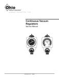
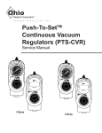
Continuous Vacuum
Regulators
Service Manual
MED
400
300
60
100
120
-mmHg
500
60
140
40
160
HIGH
LOW
80
70
600
20
180
200
F U L L V AC
6700-0072-000 RevD
10/2007
80
50
40
High Flow
High Vacuum
20
90
700
200
30
10
100
- kP
a
Hg
-mm
100
User Responsibility
This Product will perform in conformity with the description thereof contained in this manual and accompanying
labels and/or inserts, when assembled, operated, maintained and repaired in accordance with the instructions
provided. This Product must be checked periodically. A
malfunctioning Product should not be used. Parts that
are broken, missing, plainly worn, destroyed or contaminated, should be replaced immediately. Should such
repair or replacement become necessary, Ohio Medical
recommends that a telephonic or written request for service advice be made to the nearest Ohio Medical Service
Office. This Product or any of its parts should not be
repaired other than in accordance with written instructions provided by Ohio Medical, or altered without the
prior written approval of Ohio Medical’s Safety
Department. The user of this Product shall have the sole
responsibility for any malfunction which results from
improper use, faulty maintenance, improper repair, damage, or alterations by anyone other than Ohio Medical
Corporation.
Important: Federal law in the U.S.A. and Canada
restricts this device to sale by or on the order of a
licensed medical practitioner. This device is to be used
only by persons who have been adequately instructed in
its use.
Important: This document is not to be reproduced in any
manner, nor are the contents herein to be disclosed to
anyone without the express authorization of Ohio
Medical Corporation.
User Responsibility
The procedures described in this service manual should
be performed by competent individuals who have a general knowledge of and experience with devices of this
nature. No repairs should ever be undertaken or attempted by anyone not having such qualifications.
Genuine replacement parts manufactured or sold by
Ohio Medical must be used for all repairs.
Read completely through each step in every procedure
before starting the procedure; any exceptions may result
in a failure to properly and safely complete the attempted procedure.
User Responsibility
CCW
MAX
in Hg
kPa
LPM
mm Hg
°C
°F
N-m
ft-lb
oz
DISS
OES
NCG
NPT
NPTF
MPTS
gal
PTFE
Counterclockwise (Anti-clockwise)
Full Line Vacuum
Inches of mercury
Kilo pascals (kPa x 7.50 = mm Hg)
Liters per minute
Millimeters of mercury (mm Hg x .133 = kPa)
Degrees Celsius
Degrees Fahrenheit
Newton-Meter (N-m x .737 = ft-lb)
Foot-Pound Force (ft-lb x 1.356 = N-m)
Ounces
Diameter Index Safety System
Oxequip Suction
National Compressed Gases (Chemetron)
National Pipe Thread (USA)
National Pipe Thread Female (USA)
Multi-Purpose Therapy Stand
Gallon
Teflon®
6700-0072-000 RevD
10/2007
Table of Contents
1/Precautions
1.1 Definitions . . . . . . . . . . . . . . . . . . . . . . . . . . .1-1
1.2 Warnings . . . . . . . . . . . . . . . . . . . . . . . . . . . .1-1
1.3 Cautions . . . . . . . . . . . . . . . . . . . . . . . . . . . . .1-2
3/Description and Specifications
3.1 Description . . . . . . . . . . . . . . . . . . . . . . . . . . .3-1
3.2 Specifications . . . . . . . . . . . . . . . . . . . . . . . . .3-2
8/Service Checkout Procedure
8.1 Set-up . . . . . . . . . . . . . . . . . . . . . . . . . . . . . .8-1
8.2 Flow Test . . . . . . . . . . . . . . . . . . . . . . . . . . . .8-1
8.3 Gauge Test . . . . . . . . . . . . . . . . . . . . . . . . . . .8-2
8.3.1 High Vacuum Gauges ONLY . . . . . . . .8-2
8.3.2 Standard and Low Vacuum
Gauges ONLY . . . . . . . . . . . . . . . . . . .8-2
8.4 Regulation Test . . . . . . . . . . . . . . . . . . . . . . .8-2
8.5 Low Vacuum Regulators ONLY . . . . . . . . . . .8-2
8.6 Bleed Test . . . . . . . . . . . . . . . . . . . . . . . . . . .8-2
8.7 Leak Test - Supply Side . . . . . . . . . . . . . . . . .8-3
8.8 Leak Test - Patient Side . . . . . . . . . . . . . . . . . . .8-4
4/Operation
4.1 Equipment Set-up . . . . . . . . . . . . . . . . . . . . .4-1
4.2 Attaching the Safety Trap . . . . . . . . . . . . . . .4-2
4.3 Mode Selection . . . . . . . . . . . . . . . . . . . . . . .4-3
4.4 Setting the Suction Level . . . . . . . . . . . . . . . .4-4
4.5 Pre-Use Checkout Procedure . . . . . . . . . . . .4-4
4.6 Patient Set-up . . . . . . . . . . . . . . . . . . . . . . . .4-7
9/Maintenance
9.1 General Maintenance of Suction Equipment .9-1
9.2 Recommended Maintenance Schedule . . . . .9-1
9.2.1 Maintenance Schedule . . . . . . . . . . . . . . . . . .9-1
9.3 Repair Policy . . . . . . . . . . . . . . . . . . . . . . . . .9-2
9.4 Technical Assistance . . . . . . . . . . . . . . . . . . .9-2
9.5 Return Instructions . . . . . . . . . . . . . . . . . . . . .9-2
5/Cleaning and Sterilization
5.1 Cleaning . . . . . . . . . . . . . . . . . . . . . . . . . . . . .5-1
5.1.1 Routine Exterior Cleaning . . . . . . . . . . .5-1
5.1.2 Internal Component Cleaning . . . . . . . .5-1
5.2 Sterilization . . . . . . . . . . . . . . . . . . . . . . . . . . .5-1
10/Ordering Information
10.1 Illustrated Parts . . . . . . . . . . . . . . . . . . . . . .10-1
10.2 Service Kits . . . . . . . . . . . . . . . . . . . . . . . . .10-2
10.3 Fittings and Adapters . . . . . . . . . . . . . . . . . .10-2
10.4 North American . . . . . . . . . . . . . . . . . . . . . .10-3
10.4.1 Regulator Options . . . . . . . . . . . . . . .10-3
10.4.2 Other Options . . . . . . . . . . . . . . . . . .10-4
10.5 International . . . . . . . . . . . . . . . . . . . . . . . . .10-5
10.5.1 Regulator Options . . . . . . . . . . . . . . .10-5
10.5.2 Other Options . . . . . . . . . . . . . . . . . .10-6
2/Scope
2.1 North American Vacuum Regulators. . . . . . . .2-1
2.2 International Vacuum Regulators . . . . . . . . . .2-2
6/Troubleshooting
7/Service - Disassembly and Assembly
7.1
Service Tools and Equipment . . . . . . . . . . . .7-1
7.2
Continuous Vacuum Regulators (All Models) 7-1
7.2.1 Disassembly . . . . . . . . . . . . . . . . . . . . .7-1
7.2.2 Assembly . . . . . . . . . . . . . . . . . . . . . . . .7-3
7.3 Suction Level Limit Setting - Low
Models ONLY . . . . . . . . . . . . . . . . . . . . . . . . .7-3
7.3.1 Low Vacuum Limiting Screws . . . . . . . .7-3
7.3.2 Vacuum Relief Valve Adjustment . . . . .7-4
7.4 Regulator Module . . . . . . . . . . . . . . . . . . . . . .7-4
7.4.1 Disassembly . . . . . . . . . . . . . . . . . . . . .7-4
7.4.2 Assembly . . . . . . . . . . . . . . . . . . . . . . . .7-5
Appendix
Installation procedure for Adapters/Probes and Fittings.
A-1
6700-0072-000 RevD
10/2007
1/Precautions
1.1 Definitions
Note:
A Note provides additional information to clarify a point in the text.
Important:
An Important statement is similar to a note but of greater emphasis.
CAUTION:
A CAUTION statement is used when the possibility of damage to the equipment exists.
WARNING:
A WARNING statement is used when the possibility of injury to the patient or the operator
exists.
= Attention. Alerts you to a warning or caution in the text.
MAX
= maximum
High Flow
High Vacuum = high flow, high vacuum
High Flow
Low Vacuum = high flow, low vacuum
I (On)
= on
O (Off)
= off
=
MW
0086
European Union Representative
1.2 Warnings
The Pre-Use Checkout Procedure must be performed
before using this equipment on each patient. If the regulator fails any part of the Pre-Use Checkout Procedure, it
must be removed from service and repaired by qualified
service personnel.
Connect the Vacuum Regulator to the vacuum source
only. Connection to pressure sources even momentarily
could injure the patient or operator and damage the
equipment.
Always connect the regulator to the vacuum source and
check its operation before attaching the patient connection.
The fitting port of the regulator must be occluded when
setting the prescribed suction level. This prevents the
patient from receiving higher than required suction levels.
Do not use this device in the presence of flammable
anesthetics. Static charges may not dissipate and a possible explosion hazard exists in the presents of these
agents.
Handle in accordance with your hospital’s infection control policy.
Clean and sterilize all suction equipment before shipment or service to ensure transportation personnel
and/or service personnel are not exposed to any hazardous contamination.
Clean and sterilize all suction equipment if contaminated
before disassembly, to ensure service personnel are not
exposed to hazardous contamination.
Following sterilization with ethylene oxide, parts should
be quarantined in a well ventilated area to allow dissipation of residual ethylene oxide gas absorbed by the
material. Aerate parts for 8 hours at 130oF (54oC).
If the Vacuum Regulator is repaired or disassembled in
any manner, the Service Checkout Procedure must be
performed before using the equipment on the patient.
The Low Vacuum Limit Setting Procedure must be followed when repairing Low Vacuum Regulators. Failure
to do this may result in suction exceeding the prescribed
level.
After patient use, regulators may be contaminated.
1-1
6700-0072-000 RevD
10/2007
Precautions/1
1.3 Cautions
Do not lubricate any internal components of the regulator
module.
Do not use any Loctite® products to seal the fitting and
adapter port threads (or products which contain
Methacrylate Ester as an active ingredient).
Only competent individuals trained in the repair of this
equipment should attempt to service it.
To help prevent aspirate from entering the regulator, as a
result of misuse, an Overflow Safety Trap and suction filter should be attached prior to its use. Aspirate in the regulator will impair the operation. The use of the Overflow
Safety Trap and suction filter will help prevent this and
extend the life of the suction equipment.
Use of lubricants other than recommended may degrade
plastic or rubber components.
Prior to placing the unit back into service after repair or
dissassembly, perform the Service Check-out Procedure.
Not for Field or Transport use**
®Loctite is a registered trademark of the Loctite Corp.
** The categories of Field and Transport Use are specifically defined in ISO
10079-3 (BS 7259: Part 2). "Field" means use at accidents or emergencies outside a hospital. "Transport" means use in ambulances, cards and airplanes.
These situations may expose the equipment to uneven support, water, dirt
mechanical shock and temperature extremes. Ohio Medical suction equipment
has not been tested to comply with the specific requirements of these categories.
6700-0072-000 RevD
10/2007
1-2
2/Scope
This service manual contains service, maintenance and parts information on all models of the Continuous Vacuum
Regulator.
North American
International
2.1 North American Vacuum Regulators.
Note: Part numbers given are for Vacuum Regulators without fittings or adapters.
ME D
MED
80
60
40
160
L OW
140
HIGH
LOW
120
-mmHg
20
40
100
120
Low Vacuum
H
60
100
G
HI
80
140
mm Hg
160
20
180
200
F U L L V AC
Standard Two Mode
Continuous
6700-1225-900
0-200 mmHg-FULL VAC
Standard Three Mode
Continuous
6700-1224-900
0-200 mmHg-FULL VAC
Low Continuous
6700-1227-900
0-135 mmHg
High Three Mode
Continuous
6700-1226-900
0-760 mmHg
2.2 International Vacuum Regulators
Important: International Vacuum regulators comply with the requirements of EN ISO 10079-3 and are CE marked.
Note: Part numbers given are for Vacuum Regulators without fittings or adapters.
100
400
300
70
600
80
50
60
High Flow
High Vacuum
200
30
90
700
300
500
40
600
20
10
70
100
100
80
50
High Flow
High Vacuum
700
16
12
60
10
8
18
4
100
2
100
Hg
-mm
-k
Hg
Two Mode High Continuous
6700-1230-900
CCW
0-760 mmHg/0-100 kPa
6700-0072-000 RevD
40
6
a
- kP
Three Mode High Continuous
6700-1229-900
CCW
0-760 mmHg/0-100 kPa
2-1
140
14
20
20
10
a
- kP
-mm
200
30
90
80
120
40
20
Pa
60
10/2007
High Flow
Low Vacuum
Hg
400
500
m
-m
Two Mode Low Continuous
6700-1233-900
CCW
0-135 mmHg/0-18 kPa
Description and Specification/3
3.1 Description
WARNING Do not use this device in the presence of flammable anesthetics. Static
charges may not dissipate and a possible explosion hazard exists in the
presence of these agents.
The Continuous Vacuum Regulator is a lightweight, compact unit used throughout the hospital primarily for pharyngeal/tracheal suctioning (airway management).
Various models provide regulated or full-line vacuum for
hospital suction procedures.
There are several models of the Continuous Vacuum
Regulators. All models contain a vacuum gauge which
indicates suction supplied by the regulator. Each has a
positive pressure safety relief valve to prevent pressurization by either failed injector vacuum (venturi) units or
inadvertent cross connection to pressurized gasses. In
addition, the Low Continuous models include a vacuum
relief valve to limit maximum suction.
Some models operate in a regulated or non-regulated
(MAX) mode. Others operate only in the regulated (limited) mode.
as an automatic valve. Turning the suction control knob
adjusts the position of the regulator module and allows
selection of a predetermined level of suction when set
according to instructions.
During use, as the flow requirement increases, the valve
automatically opens to maintain suction at the preset
level. Conversely, when the flow requirement decreases,
the valve automatically closes to maintain suction at the
preset level. The same mechanism compensates for
changes in supply vacuum and automatically maintains
the pre-set suction level when set according to instructions.
1. Suction Control Knob - Allows easy adjustment of
suction to the patient.
2. Mode Selector Switch - Allows quick and easy mode
changes.
a. | (On) - Suction can be adjusted with the suction
control knob.
b. O (Off) - No suction is supplied to the patient.
c. MAX - Maximum full-line vacuum is supplied to
the patient.
3. Vacuum Gauge - The suction level to the patient is
displayed during use.
In the non-regulated (MAX) mode, the vacuum source is
connected directly to the fitting port. The regulator module is bypassed and full-line vacuum is provided.
In the regulated (limited) mode, the vacuum source is
connected through the regulator module which functions
Mode
Selector
Switch
400
300
500
Vacuum
Gauge
60
70
600
80
50
40
High Flow
High Vacuum
20
90
700
200
30
10
100
100
- kP
a
Hg
-mm
Adapter
Port
Suction
Control
Knob
Fitting Port
Front and Side View
6700-0072-000 RevD
10/2007
3-1
3/Description and Specifications
3.2 Specifications
Gauge:
Accuracy: ±5% of full scale deflection
Flow Rate:
0 to 80 LPM without fittings at full increase setting depending on supply vacuum and open
air flow
Positive Pressure Safety
Relief Valve:
Located in the vacuum supply line to prevent pressurization of the patient connection by
failed injector vacuum (venturi) units, or inadvertent cross connection to pressurized
gases
Ranges:
Gauge Range
Regulated Suction
Standard Models
High Models
Low Models
0 to 200 mm Hg/0 to 26 kPa
0 to 760 mm Hg/0 to 100 kPa
0 to 160 mm Hg/0 to 21 kPa
0 to 760 mm Hg/0 to 100 kPa
0 to 760 mm Hg/0 to 100 kPa
0 to 135 mm Hg/0 to 18 kPa*
* When measured with an independent measuring device.
Vacuum Relief Valve
(Low Vacuum models ONLY):
140 mm Hg ± 5 mm Hg/18.7 kPa ± 0.7 kPa
Weight:
(Less fittings)
11 oz/312 grams
Weight
Low Vacuum models:
(Less fittings)
12 oz/340 grams
Dimensions:
(Less fittings)
Height: 5.7 inches/145 mm
Width: 3.0 inches/76 mm
Depth: 3.8 inches/96 mm
Latex tubing, 0.25 in (6.4 mm) I.D. X
12 in (30 cm) supplied:
0 to full vacuum
Flow dependent on source and setup
Disposable tubing (Available
separate in some markets;
6 mm I.D. X 450 mm, 750 mm
and 2M) to connect regulator
and collection bottle
0 to full vacuum
Flow dependent on source and setup
Disposable Suction Filter:
0 to full vacuum
0 to 100 Lpm @ 650 mmHg (-87 kPa)
Environmental Specifications
Operating Temperature Range:
Storage Temperature Range:
Operating and Storage Relative Humidity:
3-2
40oF (4oC) to 120oF (49oC)
0oF (-18oC) to 150oF (71oC)
5 to 95%
6700-0072-000 RevD
10/2007
Operation/4
4.1 Equipment Set-up
Insert the probe into the vacuum wall outlet. If the regulator is mounted elsewhere, connect a vacuum supply
hose between the regulator’s probe adapter and the wall
outlet.
WARNING Connect the vacuum regulator to the
vacuum source only and check its
operation before attaching the patient
connection. Connection to pressure
sources, even momentarily, could
injure the patient or operator and
damage the equipment.
Note: For proper installation of Adapters/Probes and
Fittings see Appendix.
Connect the collection bottle's vacuum port to the regulator's fitting port or Overflow Safety Trap with the appropriate suction filter and vacuum tubing.
ISO 10079-3 (BS 7259: Part 2, section 5.1.2) states that
“the usable volume of the collection container shall not
be less than 500 ml.”
An Ohio Medical High Flow Suction Filter should be
used between the collection container and regulator to
prevent contamination of the regulator. Hospital-supplied suction tubing must be used between the catheter
and the collection bottle. Recommended minimum
inside diameter is 0.25 in (6 mm).
Suction Filters - Hydrophilic
Pkg of 20 6730-0350-800
Pkg of 200 6730-0351-800
Suction Filters - Hydrophobic
Tubing x
tubing nipple
Pkg of 3
6730-0570-800
Pkg of 10
6730-0571-800
Pkg of 100
6730-0572-900
1/8 NPT x
tubing nipple
6730-0580-800
6730-0581-800
6730-0582-800
Use hospital-supplied suction tubing between the end
piece and the collection container, and between the
patient port and the patient (minimum inside diameter is
6 mm [0.25 in.]).
Vacuum Port
Vacuum
Regulator
Patient Port
400
300
500
60
70
600
80
50
40
High Flow
High Vacuum
20
90
700
200
30
10
100
100
- kP
a
-mm
Hg
Disposable
Suction Filter
Connective Tubing
Overflow
Safety Trap
Collection
Bottle
Underwater Seal Line
2 cm H2O
Made in USA
Equipment Set-Up
6700-0072-000 RevD
10/2007
4-1
4/Operation
4.2 Attaching the Safety Trap
CAUTION To help prevent aspirate from entering
the regulator, wall outlet and pipeline
system as a result of misuse, an
Overflow Safety Trap should be
attached prior to its use. Aspirate in the
regulator, wall outlet and pipeline system
may impair their operation. The use of
the Overflow Safety Trap and suction filter will help prevent this and extend the
life of suction equipment.
Standard fitting
1. Raise the sleeve and insert the trap into the regulator fitting.
Sleeve
2. Turn the trap clockwise about one and a half turns to
engage the threads. The trap does not need to be
screwed tight; an O-ring in the regulator fitting provides a vacuum seal. The trap should rotate freely to
allow the desired tubing positioning.
3. Lower sleeve to lock trap in position.
DISS fitting
1. Insert trap into the regulator fitting. Situate the tubing
in the desired position.
2. Turn the DISS wing nut clockwise to engage threads
and tighten (there is no O-ring, so the vacuum seal
depends on a tight connection).
4-2
6700-0072-000 RevD
Wing nut
10/2007
Operation/4
4.3 Mode Selection
| (On) - Suction can be adjusted with the suction control
knob.
2 - Mode Switch
3 - Mode Switch
I/(On)
O (Off) - No suction is supplied to the patient.
2 - Mode Switch
3 - Mode Switch
O/(Off)
MAX - Maximum, full-line vacuum is supplied to the
patient.
Note: available on three mode vacuum regulators only.
3 - Mode Switch
MAX
6700-0072-000 RevD
10/2007
4-3
4/Operation
4.4 Setting the Suction Level
1. Turn the mode selector switch to I (On).
400
300
500
2. Occlude or clamp tubing
60
70
600
80
50
40
High Flow
High Vacuum
200
30
20
90
10
100
100
700
3. Rotate the suction control knob until the vacuum
gauge indicates the required setting.
- kP
a
Hg
-mm
WARNING The regulator fitting port or patient
connector must be occluded when
setting the prescribed suction level
so that the patient does not receive
higher than required suction.
Clamp
4.5 Pre-Use Checkout Procedure
WARNINGS The Pre-Use Checkout Procedure
must be performed before using the
equipment on each patient. If the regulator fails any part of the Pre-Use
Checkout Procedure, it must be
removed from service and repaired
by qualified service personnel.
400
300
500
60
70
600
700
40
200
30
20
10
100
- kP
a
Hg
-mm
Clamp
All tests must be performed with supply vacuum of 380
mm Hg (51 kPa) minimum.
1. Turn the mode selector switch to O (Off).
Rotate the suction control knob one full turn clockwise (increase).
Clamp tubing to occlude the fitting port. The gauge
needle should not move.
6700-0072-000 RevD
50
90
Connect the vacuum regulator to the
vacuum source only and check it's
operation before attaching the patient
connection. Connection to pressure
sources, even momentarily, could
injure the patient or operator and
damage the equipment.
4-4
80
High Flow
High Vacuum
10/2007
100
Operation/4
2. Turn the mode selector switch to I (On).
Rotate the suction control knob fully anti-clockwise
(decrease).
400
300
500
60
70
Clamp tubing. The gauge needle should not move.
600
80
50
40
High Flow
High Vacuum
200
30
20
90
10
100
100
700
- kP
a
-mm
Hg
Clamp
3. Clamp tubing.
Regulator Setting
400
300
500
60
70
600
Standard & Low: increase the suction to 100 mm Hg
(13 kPa)
High:
increase the suction to 300 mm Hg
(40 kPa)
40
700
200
30
20
90
10
100
100
- kP
a
-mm
Hg
Clamp
Slowly open and close the clamped tubing to create various flow rates through the regulator. Check that the suction level is maintained when the tubing is clamped.
For Standard 2 Mode Continuous, go to step 5.
6700-0072-000 RevD
80
50
High Flow
High Vacuum
Release
Clamp
10/2007
4-5
4/Operation
4a. High and Standard 3 Mode Continuous
Turn the mode selector to MAX. Clamp tubing and
check that the gauge needle indicates the maximum
available suction.
400
300
500
50
60
70
600
40
80
20
90
Turn the mode selector to I (On).
700
200
30
High Flow
High Vacuum
100
10
100
- kP
a
Hg
-mm
Clamp
4b. Low Continuous
Clamp tubing and rotate knob fully clockwise
(increase) to verify the suction level does not exceed
150 mm Hg (20 kPa).
100
80
120
140
16
14
12
60
10
8
18
6
20
Pa
2
-k
High Flow
Low Vacuum
Clamp
4-6
6700-0072-000 RevD
40
4
10/2007
m
-m
20
Operation/4
5. Reduce the suction level to zero and set the mode
selector switch to O (Off).
400
300
500
60
70
600
80
50
40
High Flow
High Vacuum
700
200
30
20
90
10
100
100
- kP
a
-mm
Hg
4.6 Patient Setup
1. Make sure the Pre-Use Checkout Procedure has
been performed.
2. Turn the mode selector switch to I (On) and clamp
tubing.
400
300
500
60
70
600
80
50
40
High Flow
High Vacuum
700
3. Set the prescribed suction level.
200
30
90
20
10
100
100
a
- kP
-mm
Hg
WARNING The regulator must be occluded when
setting the prescribed suction level
so that the patient does not receive
higher than required suction.
Clamp
Underwater Seal Line
2 cm H2O
Made in USA
6700-0072-000 RevD
10/2007
4-7
4/Operation
Patient
Connective
Tubing
4. Turn the mode selector switch to O (Off).
5. Attach tubing to the vacuum port of the collection
container.
400
300
500
50
60
70
600
40
80
200
30
High Flow
High Vacuum
20
90
100
10
100
700
- kP
a
Hg
-mm
Underwater Seal Line
2 cm H2O
Made in USA
6.
Turn the mode selector switch to I (On).
Important: The Low models do not
deliver suction in excess of 150
mm Hg (20 kPa).
400
300
500
60
70
600
80
50
40
High Flow
High Vacuum
700
200
30
20
90
10
100
100
a
- kP
-mm
Hg
Underwater Seal Line
2 cm H2O
Made in USA
4-8
6700-0072-000 RevD
10/2007
Cleaning and Sterilization/5
5.1 Cleaning
WARNING
absorbed by the material. Aerate
parts for 8 hours at 130oF (54oC).
After patient use, regulators may be
contaminated. Handle in accordance
with your hospital’s infection control
policy.
CAUTION Do not steam autoclave or liquid sterilize
the Continuous Vacuum Regulator.
Severe impairment to the operation of
the regulator will result. The only acceptable method of sterilization is with gas
(ethylene oxide).
CAUTION Sterilization with ethylene oxide mixtures may cause crazing (minute superficial cracking) of some plastic parts.
Crazing will be more pronounced when
mixtures containing Freon® are used.
5.1.1 Routine Exterior Cleaning
Routine cleaning of the regulator is recommended as a
standard procedure after each use.
Wipe all exterior surfaces with a solution of water and
mild detergent.
5.1.2 Internal Component Cleaning
CAUTION Cleaning the gauge may result in damage.
Note: The Vacuum Regulator should only be sterilized if
it is contaminated or maintenance is to be performed.
The regulator requires cleaning if it becomes flooded with
patient fluid as a result of misuse.
1. The regulator should be sterilized with the mode
selector switch in the | (On) position.
1. Refer to the Service - Disassembly and Assembly
instructions.
2. The only acceptable method of sterilization is with
ethylene oxide. Ethylene oxide mixtures can be used
at temperatures of 125 to 135 °F (52 - 57 °C). If this
temperature cannot be obtained, room temperature
sterilization with 100% ethylene oxide can also be
used. Sterilization is not recommended as a standard procedure after each use.
2. All internal components, with the exception of the
gauge, may be cleaned with a solution of warm water
and mild detergent, preferably an enzymatic cleaner.
3. Dry all components with a lint free cloth before
assembly.
5.2 Sterilization
Should misuse occur, resulting in accidental flooding of
the regulator, the regulator may be sterilized using
Ethylene Oxide (ETO). After sterilization, follow the service checkout procedures in Section 8.
WARNING
3. After each sterilization, check the condition of the
internal filter. If the filter appears to have shrunk,
replace it before placing the regulator back in service.
4. Adequately aerate the regulator prior to disassembly,
shipment or use. Aerate parts prior to reassembly.
Following sterilization with ethylene
oxide, parts should be quarantined in
a well ventilated area to allow dissipation of residual ethylene oxide gas
®Freon is a registered trademark of the DuPont Company.
6700-0072-000 RevD
10/2007
5-1
6/Troubleshooting
Problem
Possible Causes
Remedy
A. No gauge indication and no suction in any setting
1. No supply vacuum
1. Correct supply problems
2. Kinked tube
2. Straighten tube
3. Poor connection
3. Check all connections and seals
4. Blocked adapter port
4. Unblock port
5. Blocked backplate
5. Clean with soap and water and
pipe cleaner
6. Blocked adapter
6. Replace adapter
7. Blocked wall outlet
7. Unblock outlet
1. Blocked gauge pressure sensing
orifice
1. Clean or replace gauge
2. Gauge mechanism locked by
debris
2. Clean or replace gauge
3. Gauge mechanism damaged
3. Replace gauge
1. Blocked fitting port
1. Clean port
2. Overflow Safety Trap shut-off
2. Reset flow and/or empty trap
3. Blocked external filter
3. Replace filter
4. Blocked fitting
4. Clean fitting
1. Mode selector switch in MAX
position
1. Switch to I(On)
2. Regulator module small o-ring
failure
2. Replace rubber components with
regulator module replacement kit
3. Regulator module diaphragm
rupture
3. Replace rubber components with
regulator module replacement kit
4. Regulator module stem screw
loose
4. Tighten stem screw
1. Partial blockage in wall supply
1a. Confirm wall supply open air flow
meets minimum hospital requirements
B. No gauge indication but suction
is being delivered
C. Gauge indication but no suction
is being delivered
D. Suction level cannot be adjusted
E. Insufficient flow through regulator
1b. Unblock if necessary
2. Partial blockage in regulator
2a. Perform the Flow Test in the
Service Checkout Procedure
Section of this manual
2b. Clear blockage if necessary
6-1
6700-0072-000 RevD
10/2007
Troubleshooting/6
Problem
Possible Causes
Remedy
F.
1. Damaged gauge
1. Replace gauge
G. With the fitting port occluded,
unable to decrease the suction
level and gauge needle does not
return to zero when switched to
O (Off)
1. Blocked filter and/or orifice
1. Clear orifice and replace filter
2. Damaged gauge
2. Replace gauge
H. No suction in any setting and
whistling noise from inside the
regulator
1. Positive pressure safety relief
valve failure
1. Replace positive pressure safety relief valve
2. Vacuum relief valve failure (low
models ONLY)
2. Replace o-ring and ensure that
the steel ball is present and
clean
Inaccurate gauge reading
Note: All gauge needles should
come to rest within the zero
range bracket or return to the
stop pin when no suction is
being supplied.
6700-0072-000 RevD
10/2007
6-2
7/Service - Disassembly and Assembly
7.1 Service Tools and Equipment
CAUTION Use of lubricants other than recommended may degrade plastic or rubber
components.
The following items should be on hand during any service procedure.
•
Supply vacuum: 500 mm Hg/ ± 10 mmHg (67 kPa ±
1.3 kPa) & 50 LPM open air flow minimum
•
Supply Vacuum Regulator with Gauge, 760 mm Hg
(101.3 kPa) Full Scale.
•
Low Vacuum Calibration Gauge, 225 mm Hg (30
kPa) Full Scale* (Ohio Medical P/N 6700-0353-800)
•
High Vacuum Calibration Gauge, 760 mm Hg (101.3
kPa) Full Scale*(Ohio Medical P/N 6700-0352-800)
•
50 LPM Flowmeter (Ohio Medical P/N 6700-0355800)
•
Hexagonal Allen Wrench 3/32 inch
•
Phillips Head Screwdriver, No. 2
•
Flat Head Screwdriver, 1/4 inch
•
Pliers
•
Dow® 111 Grease (Ohio Medical P/N 6700-0074200)
•
Loctite® 242 Removable Thread Locker (Ohio
Medical P/N 0220-5016-300)
•
Tubing Clamp
•
Bubble Leak Tester
•
Tweezers (Filter Remover)
•
Wooden Tooth Pick (O-ring Remover)
•
Pipe Cleaner
7.2 Continuous Vacuum Regulators (All
Models)
7.2.1 Disassembly
WARNINGS If the Vacuum Regulator is repaired
or disassembled in any manner, the
Service Checkout Procedure must be
performed before using the equipment on a patient.
Clean and sterilize all suction equipment if contaminated before disassembly, to ensure service personnel
are not exposed to hazardous contamination.
When servicing a Low Vacuum
Regulator, perform the Vacuum Relief
Valve Adjustment and Low Vacuum
Limit Setting Procedure.
CAUTION (*) Accuracy: ±1% of full scale deflection
®Dow is a registered trademark of the Dow Chemical Corporation
7-1
6700-0072-000 RevD
10/2007
The gauge assembly must be handled
with utmost care to retain its precision. If
the lens is removed, do not rest the
gauge on its face.
Service - Disassembly and Assembly/7
1.
2.
3.
2
Cover Screw (4)
Cover Assembly
Low Vacuum Limiting Screws
(2) (Not Shown) (On old versions of the
Low Models Only)
1
3
12
11
1
2
1.
2.
3.
4.
5.
6.
7.
8.
9.
10.
11.
12.
13.
14.
Mode Selector Switch
Switch Plate
13
Screw
14
O-ring, Vacuum Relief Valve
(Low Models Only)
9
Vacuum Relief Valve & O-ring
(Low Models Only)
Gauge Assembly (includes gauge, o-rings, and lens)
Lens
O-ring (2), Gauge
Regulator Module
Positive Pressure Safety Relief Valve
Filter (Internal)
Base
O-ring, Stem
O-ring, Regulator Module
3
1
5
4
8
7
6
1. Remove the four cover screws from the back of the regulator.
2. Carefully pull the cover assembly off the back body.
3. To remove the gauge assembly, grasp the assembly and
pull straight out. The snap-fit lens can also be removed
(if applicable) for replacement.
4. To remove the regulator module from the cover assembly, rotate the suction control knob counterclockwise until
the regulator module is free.
5. Using tweezers, remove the filter. Replace with a new filter.
Pull down plastic tab with
right index finger while
holding gauge
6. Grasp the positive pressure safety relief valve, and pull it
from the back body.
7. Remove the mounting screw from the switch plate
assembly and remove the switch plate and mode switch.
Snap Fit Lens Removal
8. Low models ONLY: Grasp the vacuum relief valve and
pull it from the back body.
6700-0072-000 RevD
10/2007
7-2
7/Service - Disassembly and Assembly
7.2.2 Assembly
CAUTION
To prevent stripping the plastic threads,
place the screw in the hole and turn
counterclockwise until it drops into the
original thread. Tighten screw.
7.3 Suction Level Limit Setting-Low Models
ONLY
WARNING
1. Place the positive pressure safety relief valve in position and push onto the back body.
2. Low models ONLY: Lubricate the vacuum relief valve
O-ring and install it in the valve housing.
3. Lubricate the switch gasket surface with a thin coating of Dow 111 Grease. Place the mode switch on
the base with the arrow at 12 o’clock. Place the
switch plate onto the switch so that the OFF/O is
under the arrow. Install and tighten the mounting
screw. Test the mode switch at all positions.
4. Place the internal filter into the proper cavity and
push until it hits the bottom of the base.
5. Place the regulator module into the cover with the
screw thread facing the knob. Align the protruding
ears at 3 and 9 o’clock and rotate the suction control
knob clockwise until the threads engage.
6. Install the snap-fit lens by placing one of the retaining tabs over the edge of the gauge face, and then
pressing lightly until the other tab snaps onto the
gauge face. Rotate the lens to confirm proper installation.
7. Install the gauge assembly by lubricating the gauge
o-rings with a thin coating of Dow 111 Grease and
pushing the gauge into the base mount. Ensure that
the gauge is properly aligned.
The design of the low continuous vacuum regulator has
been changed to eliminate the low vacuum limiting set
screws located inside the cover behind the suction control knob. The vacuum relief valve has also been
changed to limit the vacuum to the same level as the set
screws did. This new vacuum relief valve has four vent
holes; the old valve had two. If a new cover is used, a
new vacuum relief valve must be used.
Versions with limiting screws have two means of limiting
the suction level:
1. Low vacuum limiting screws in the cover; these can
be set at 140 mmHg/19 kPa (± 10 mmHg/1.0 kPa).
2. Vacuum relief valve; this can be set at 165 mmHg ±
15 mmHg (22 kPa ± 2 kPa).
These vacuum limit settings may be reduced to
accommodate user requirements. If the vacuum limit
settings are reduced, the vacuum relief valve must
be set 25 mmHg ± 15 mmHg (3 kPa ± 2 kPa) higher
than the vacuum limiting screws.
Versions without the limiting screws use only the relief
valve to limit the suction level. The relief valve can be set
at 140 mmHg ± 5 mmHg (18.7 kPa ± 0.7 kPa).
8. Place the cover assembly onto the base and push
together until the base and back of the cover are
flush.
9. Install the 4 cover screws.
7-3
6700-0072-000 RevD
This Low Vacuum Limit Setting
Procedure must be followed when
repairing Low Vacuum Regulators.
Failure to do this may result in suction exceeding the prescribed level.
10/2007
Service - Disassembly and Assembly/7
7.3.1 Low Vacuum Limiting Screws
CAUTION When adjusting the vacuum limiting
screws, be sure to adjust them to an equal height.
Cover and Knob
Assembly
CAUTION Remove the “Increase” label carefully. Press firmly in place when replacing.
1. Remove the “Increase” label and place it aside. Be
careful not to damage the face or glued back of the
label.
2. Adjust the two vacuum limiting screws located
behind the suction control knob until they are the
same height in the case. Use a 3/32” hexagonal allen
wrench.
Allen
Wrench
Increase Label
3. Connect the vacuum supply to the adapter port and
occlude the fitting port.
Set Screws
Setting the Vacuum Limiting Screws
4. Be certain that the screws remain at an equal height
by adjusting both low vacuum limiting screws the
same amount and in the same direction. Adjust the
screws to supply a maximum vacuum of 150 mm Hg
(20 kPa) and not less than 130 mm Hg (17 kPa).
7.3.2 Vacuum Relief Valve Adjustment
1. Remove the cover.
2. Connect the supply vacuum to the adapter port.
Valve
Body
3. Turn the mode selector switch to I/ON.
Steel
Ball
4. Occlude the fitting port.
5. Slowly pull the regulator module away from the base.
Note the suction level at which the relief valve opens.
The relief valve should open at 165 mmHg ± 15
mmHg (22 kPa ± 2 kPa) on units with limiting
setscrews and140 mmHg ± 5 mmHg (18.7 kPa ± 0.7
kPa) for units without limiting setscrews.
6. If adjustment is required, grip the vacuum relief valve
firmly with pliers and rotate the screw about 1/8 turn
with a screwdriver. Repeat the previous step and
check the suction level at which the valve opens.
Note: Clockwise rotation will increase the suction
level at which the relief valve opens.
Counterclockwise rotation will decrease it.
WARNING Excess Loctite® may seal the steel
ball to the seat. This will disable the
vacuum relief valve and may allow
suction to exceed the preset limit.
O-Ring
Screw
w/Magnet
Loctite
242
Vacuum Relief Valve
CAUTION When Loctite is used on the vacuum
relief safety valve, ensure that it only
contacts the metal parts. Loctite causes
many plastic parts to deteriorate.
7. Lock the adjusting screw with a drop of removable
thread locker such as Loctite 242. Repeat step 5 to verify the vacuum relief valve setting.
® Loctite is a registered trademark of the Loctite Corporation.
6700-0072-000 RevD
10/2007
7-4
7/Service - Disassembly and Assembly
7.4 Regulator Module
WARNING
If repairing or replacing a regulator
module on a Low Vacuum Regulator,
you must perform the Suction Level
Limit Setting-Low Models ONLY
Procedure. Failure to do this may
result in suction exceeding the prescribed level.
CAUTION Do not lubricate any internal components of the regulator module.
The cap screws can strip the regulator
module housing threads if they are
screwed in too tight.
7.4.1 Disassembly
1. Remove the cap screws (2) and remove the cap.
2. Remove the o-rings (2).
3. Observe the position of the diaphragm convolution to
aid in assembly.
4. Withdraw the diaphragm/stem assembly from the
housing.
5. Remove the spring.
6. Grasp the stem with your fingers and unscrew the
stem screw.
11
7. Remove the retainer, diaphragm and piston from the
stem.
10
8
7
6
5
3
4
2
1
Regulator Module Parts and Descriptions
7-5
6700-0072-000 RevD
10/2007
9
11
1.
2.
3.
4.
5.
6.
7.
8.
9.
10.
11.
O-ring, Stem
O-ring
Housing
Stem
Spring
Piston
Diaphragm
Retainer
Stem Screw
Cap
Cap Screw
Service - Disassembly and Assembly/7
7.4.2 Assembly
1. Return the diaphragm to its original position (convoluted), with the molded number facing the retainer.
2. Assemble the diaphragm onto the retainer by lining
up their center holes as shown in the diagram.
3. Insert the piston into the diaphragm and ensure that
the retainer mates with the recess in the piston.
4. Insert the stem through the piston.
5. Holding the retainer/diaphragm/piston/stem as an
assembly with your fingers, insert the stem screw
and tighten.
6. Place the spring in the housing.
7. Insert the retainer/diaphragm/piston/stem assembly
through the spring and into the cavity in the housing.
Fit the diaphragm bead into the groove in the housing.
Retainer
Stem
8. Install the cap and the two cap screws.
9. Apply a small amount of Dow® 111 Grease to the orings only.
Set Screw
Piston
Diaphragm
10. Install o-rings onto the stem and housing.
Diaphragm Assembly
6700-0072-000 RevD
10/2007
7-6
8/Service Checkout Procedure
8.2 Flow Test
WARNING If the Vacuum Regulator is repaired or
disassembled in any manner, the
Service Checkout Procedure must be
performed before using the equipment on a patient.
1. Connect the regulator's fitting port to the flowmeter
with tubing.
2. Rotate the suction control knob fully clockwise
(increase).
Important: This entire Service Checkout Procedure
must be performed in numerical order.
8.1 Set-up
3. Turn the mode selector switch to I (On) and verify
that the flow rate exceeds 30 LPM.
1. Verify that there is 500 mmHg ± 10 mmHg (67 kPa ±
1.3 kPa) vacuum on the supply gauge.
4. Turn the mode selector switch to MAX (if available)
and verify that the flow rate exceeds 30 LPM.
2. The supply open flow must be 50 LPM minimum.
5. Turn the mode selector switch to O (Off).
3. Connect the supply vacuum to the adapter port.
6. Disconnect the flowmeter.
Supply Vacuum gauge
0-760 mmHg (0-101.3 kPa)
Mode
Selector
Switch
MED
100
60
120
mmHg
140
40
160
HIGH
LOW
80
20
Supply Vacuum Reg. set to
500 mmHg + 10 mmHg
(64 kPa + 1.3 kPa)
180
200
F U L L V AC
Occluded
Flowmeter
50 LPM
High Vacuum
Calibration Gauge
760 mmHg/101.3 kPa
Low Vacuum
Calibration Gauge
225 mmHg/30 kPa
Service Checkout Tests
8-1
6700-0072-000 RevD
10/2007
Supply Vacuum
500 mmHg (67 kPa)
Minimum and
Open Flow of
50 LPM Minimum
Service Check Out Procedure/8
8.3 Gauge Test
8.4 Regulation Test
Note: All Ohio Medical gauges are supplied with an accuracy of ±5% of full scale deflection throughout their
range. The table below is provided for reference.
1. Disconnect the calibration gauge and occlude the fitting port.
Gauge
Standard
Vacuum
Low
Vacuum
High
Vacuum
Range
0-200 mmHg (0-26 kPa)
Tolerance
±10 mmHg (1.3 kPa)
0-160 mmHg (0-20 kPa)
±8 mmHg (1.1 kPa)
0-760 mmHg (0-100 kPa)
±38 mmHg (5 kPa)
Note: All gauge needles should come to rest within the
zero range bracket or return to the stop pin when no suction is being supplied. Gauges which do not comply may
be out of calibration.
2. If using a High Vacuum Regulator, set its gauge to
300 mmHg (40 kPa). If using a Low or Standard
Vacuum Regulator, set its gauge to 100 mmHg/14
kPa.
3. Open and close the fitting port several times.
4. With the fitting port occluded, the gauge should
return to the setting listed in step 2 within a tolerance
of:
±38 mmHg (5 kPa) for high vacuum gauge
or
When checking gauge accuracy, be sure that the calibration gauge has an accuracy of 1% of full scale deflection
or better.
±10 mmHg (1.3 kPa) for the standard
vacuum gauges
8.3.1 High Vacuum Gauges ONLY
or
1. Connect the regulator's fitting port to the high calibration gauge with tubing.
±8mmHg (1.1 kPa) for the low vacuum gauge.
2. Turn the mode selector switch to I (On).
8.5 Low Vacuum Regulators ONLY
1. Occlude the fitting port.
3. Assure that the gauge is in agreement with the high
vacuum calibration gauge within the ±38 mmHg (5
kPa) tolerance. Recommended test points are 100,
300, and 500mm Hg.
8.3.2 Standard and Low Vacuum Gauges ONLY
2. Rotate the suction control knob fully clockwise
(increase).
3. Verify that the suction delivered does not exceed 150
mm Hg (20 kPa) or the maximum suction requested
by the clinician.
1. Connect the regulator's fitting port to the low calibration gauge with tubing.
2. Turn the mode selector switch to I (On).
Note: For setting the Suction level limit, refer to
Suction Level Limit Setting-Low Models ONLY.
8.6 Bleed Test
3. Assure that the gauge is in agreement with the low
vacuum calibration gauge within the ±10 mmHg (1.3
kPa) or the ±8 mmHg (1.1 kPa) tolerance for standard and low gauges respectively. Recommended
test points are 40, 80, and 140 mmHg.
4. For the Standard Gauge ONLY: Rotate the suction
control knob fully clockwise (increase) and verify its
reading is in the FULL VAC range.
1. Occlude the fitting port and set the vacuum level to
100 mm Hg (14 kPa).
2. Turn the selector switch to O (Off) and observe the
gauge needle. It must return to the zero range bracket or stop pin within 10 seconds.
6700-0072-000 RevD
10/2007
8-2
8/Service Checkout Procedure
8.7 Leak Test - Supply Side
1. Connect the supply vacuum tubing to port “A” of the Bubble Leak Tester.
2. Connect port “B” of the Bubble Leak Tester to the regulator adapter port.
3. Turn the mode selector switch to O (Off). Allow the fitting port to be open to air.
4. Wait 20 seconds. No More than 6 bubbles should appear in the next ten seconds.
Important: Prior to venting port "A" of the Bubble Leak Tester to atmosphere (i.e. turning the supply regulator off),
ensure the tubing from port "B" has been disconnected from the adapter port of the vacuum regulator.
Vacuum
Regulator
Supply Vacuum Gauge
0-760 mmHg (0-101.3 kPa)
Supply Regulator
500 mmHg (67 kPa)
Adapter Port
Supply
Vacuum
Fitting port
Port B
Port A
Sealed
1/4” I.D.
Clear Tubing
1.0 in.
Water
Bubble Leak
Tester
Bubble Leak Test - Supply Side
8.8 Leak Test - Patient Side
1. Connect the supply vacuum tubing to the regulator adapter port.
2. Connect the regulator fitting port to port “A” of the Bubble Leak Tester with tubing. Allow port “B” of the Bubble
Leak Tester to be open to air.
3. Rotate the suction control knob a minimum of one full turn clockwise (increase). No bubbles should appear in the
next ten seconds.
Port B
MED
80
Vacuum
Regulator
60
100
120
mmHg
140
40
160
20
180
Sealed
200
Bubble Leak Test -Patient Side
6700-0072-000 RevD
10/2007
1/4” I.D.
Clear
Tubing
F U L L VAC
Suction
Control
Knob
8-3
Port A
HIGH
5. Turn the mode selector switch to I (On).
No bubbles should appear in the next ten
seconds.
Mode
Selector
Switch
LOW
4. Rotate the suction control knob fully
counterclockwise (decrease).
1.0 in.
Water
Bubble Leak
Tester
Maintenance/9
WARNING The Pre-Use Checkout Procedure
must be performed before using this
equipment on each patient. If the regulator fails any part of the Pre-Use
Checkout Procedure, it must be
removed from service and repaired
by qualified service personnel.
WARNING Clean and sterilize all suction equipment if contaminated before disassembly, to ensure service personnel
are not exposed to hazardous contamination.
Continuous Vacuum Regulators should be kept in
use or used on a rotating basis.
Unused equipment may tend to deteriorate.
Maintenance of the vacuum piping system is as important as maintenance of the suction equipment. The use
of Collection Bottles with reliable shut-off valves,
Overflow Safety Trap assemblies and disposable suction
filters will protect the regulator and piping system. The
flow rate at the wall outlet should be checked on a yearly basis and suitable cleaning of the outlets should be
performed. The flow rate measurement should meet
local standards.
Routine maintenance and inspection are important to the
performance of suction equipment. The following is a
recommended list for care of suction equipment after
each patient use.
1. Perform a thorough cleaning by washing all bottles,
tubing, metal connectors, etc, and removing all
residue.
2. Wipe all exterior surfaces with a solution of water
and mild detergent.
3. Perform a careful visual inspection.
4. Check that the High Flow Disposable Suction Filter is
clean and in good condition.
5. Check that all tubing is in good condition and connected securely to the correct ports.
6. Check the floats in the Overflow Safety Trap and
Collection Bottle for correct operation.
7. Perform the Pre-Use Checkout Procedure.
9.2 Recommended Maintenance Schedule
In addition to the Pre-Use Checkout Procedure, the following periodic maintenance should be performed.
9
.2.1 Maintenance Schedule
Item
Minimum Frequency
Comments
Service Checkout
Every 12 months
If the regulator does not pass the
Procedure Service Checkout Procedure,
refer to the Troubleshooting section of
this manual. Repair as necessary.
Elastometric
As Required
Components,O-rings,
switch gasket,
reg. module diaphragm,
positive pressure safety valve) and Internal Filter
6700-0072-000 RevD
Cleaning and replacement interval
will depend greatly on hours of usage and
environmental conditions. Replace and
repair as necessary.
10/2007
9-1
9/Maintenance
9.3 Repair Policy
9.5 Return Instructions
WARNING Clean and sterilize all suction equipment before shipment or service to
ensure transportation personnel
and/or service personnel are not
exposed to any hazardous contamination.
CAUTIONS Do not steam autoclave or liquid sterilize
the Continuous Vacuum Regulator.
Severe impairment to the operation of
the regulator will result. The only acceptable method of sterilization is with gas
(ethylene oxide).
1. Call 866-549-6446 for a returned goods authorization.
Only competent individuals trained in the
repair of this equipment should attempt
to service it.
5. Ohio Medical now offers a ten year warranty on vacuum regulators sold on or after July 1, 2005. If the
vacuum regulator was purchased on or after July 1,
2005 and is less than ten years old or if the vacuum
regulator is covered under the previous warranty and
is less than five years old, include the warranty information that came with the device and a copy of the
invoice.
Do not use malfunctioning equipment. Make all necessary repairs. Have the equipment repaired by qualified
service personnel or by Ohio Medical. Parts listed in the
service manual for this product may be repaired or
replaced by a competent, trained person who has experience in repairing devices of this nature. After repair, perform the Service Checkout Procedure to ensure that it is
functioning properly, and complies with the published
specifications.
9.4 Technical Assistance
2. Clean and sterilize the Vacuum Regulator.
3. Package the Vacuum Regulator securely for protection; preferably in the original container.
4. Include a letter describing in detail any difficulties
experienced with the Vacuum Regulator. Include the
person, title, and telephone number to contact for
functional questions.
6. Include a purchase order to cover repair of a regulator not under warranty.
7. Ship the Vacuum Regulator prepaid. Write your
return address and billing address information on the
package or letter that comes with the package.
If technical assistance is required, contact Ohio Medical
technical support or field operations listed on the back
cover.
For all Repairs Contact your nearest Ohio Medical office
or authorized Ohio Medical Distributor.
9-2
6700-0072-000 RevD
10/2007
Ordering Information/10
10.1 Illustrated Parts
Description
2
Part Number
1. Cover Screw (4) . . . . . . . . . . . . . . .6700-0152-400
2. Cover Assembly
Low* . . . . . . . . . . . . . . . . . . . . . . . .6700-0629-850
Std/High . . . . . . . . . . . . . . . . . . . . .6700-0628-850
3. Low Vacuum Limiting Screw (2)
(Not Shown) (Low Models Only) . .6700-0058-400
1
3
* If current unit does not have limit screws inside the
cover behind the control knob and the relief valve has 4
vent holes, the Std/High part can be purchased.
12
11
1
2
3
5
10
13
4
14
8
9
7
Description . . . . . . . . . . . . . . . . . . . . . . . .Part Number
1. Switch . . . . . . . . . . . . . . . . . . . . . . .6700-0078-500
2. Switch Plate
3 Mode . . . . . . . . . . . . . . . . . . . . . .6700-0193-500
2 Mode/Low . . . . . . . . . . . . . . . . . .6700-0194-500
3. Screw . . . . . . . . . . . . . . . . . . . . . . .6700-0152-400
4. O-ring, Vacuum Relief Valve
(Low Models Only) . . . . . . . . . . . . .6700-0135-500
5. Vacuum Relief Valve
& O-ring (Low Models Only) . . . . . .6700-0660-850
6. Gauge Assembly (Includes gauge, o-rings and lens)
North American Standard,
0-200 mmHg . . . . . . . . . . . . . . . . . .6700-0050-200
North American Low, 0-160 mmHg 6700-0050-202
North American High, 0-760 mmHg 6700-0050-201
International Low . . . . . . . . . . . . . .6700-0050-205
International High . . . . . . . . . . . . . .6700-0050-204
7. Lens . . . . . . . . . . . . . . . . . . . . . . . .6700-0087-500
8. O-ring (2), Gauge . . . . . . . . . . . . . .6700-0130-500
9. Regulator Module
Standard/High Models . . . . . . . . . .6700-1225-800
Low * . . . . . . . . . . . . . . . . . . . . . . . .6700-0428-800
6
10. Positive Pressure Safety Relief
Valve . . . . . . . . . . . . . . . . . . . . . . . .6700-0115-800
11. Filter (Internal) . . . . . . . . . . . . . . . .0206-5159-300
12. Base
North American Standard & High
(2 & 3 Mode) . . . . . . . . . . . . . . . . . .6700-0018-203
North American Low . . . . . . . . . . . .6700-0029-203
International Low . . . . . . . . . . . . . .6700-0029-200
International High . . . . . . . . . . . . . .6700-0018-200
13. O-ring, Stem . . . . . . . . . . . . . . . . . .0210-0527-300
14. O-ring, Regulator Module . . . . . . . .6700-0136-500
* If current unit does not have limit screws inside the
cover behind the control knob and the relief valve has 4
vent holes, the Std/High part can be purchased.
6700-0072-000 RevD
10/2007
10-1
10/Ordering Information
10.2 Service Kits
O-rings and Filters Kit . . . . . . . . . . . . . .0221-5871-870
Includes the internal filter and 6 O-rings
Standard and High Models . . . . . . . . . .6700-0043-200
Includes the following parts:
O-ring (2), Gauge
Filter (Internal)
Positive Pressure Safety Relief Valve
Regulator Module Replacement Kit
Low Models . . . . . . . . . . . . . . . . . . . . . .6700-0044-200
Includes the following parts:
O-ring (2), Gauge
Filter (Internal)
Positive Pressure Safety Relief Valve
Regulator Module Replacement Kit
O-ring, Vacuum Relief Valve
Increase Label (Universal)
Regulator Module
Continuous Regulator Module (6) . . . . .6700-0028-700
Low Cont. Regulator Module (6)* . . . . .6700-0190-700
Regulator Module Replacement
Parts Kit (6) . . . . . . . . . . . . . . . . . . . . . .6700-0031-700
The following kits for U.S. regulators only
Standard Vacuum Gauge (4) . . . . . . . .0205-8689-870
High Vacuum Gauge (4) . . . . . . . . . . . .6700-0097-200
Low Vacuum Gauge (4) . . . . . . . . . . . .6700-0098-200
Standard & High Backplate (4) . . . . . . .6700-0194-700
Low Backplate (4) . . . . . . . . . . . . . . . . .6700-0198-700
* If current unit does not have limit screws inside the cover behind the control
knob and the relief valve has 4 vent holes, the continuous regulator modules
can be purchased.
Replacement Kit . . . . . . . . . . . . . . . . . .6700-0030-700
Includes the following parts:
O-ring, Stem
These parts are available
O-ring
only in kit form. If other
Diaphragm
parts are needed for reStem Screw
placement, the entire
Cap Screw (3)
Module must be ordered
(6700-1225-800).
10.3 Fittings and Adapters
1
2
Description . . . . . . . . . . . . . . . . . . . . . . . .Part Number
1. Diamond Adapter . . . . . . . . . . . . . .0221-2685-802
2. NCG Adapter (Round) . . . . . . . . . .0221-0204-802
NCG Adapter (Rectangle) . . . . . . . .0221-0205-800
3. Schrader Adapter . . . . . . . . . . . . . .0221-0690-731
4. DISS Union Nut & Gland . . . . . . . .6700-0094-700
5. DISS Hand-I-Twist Nut & Gland . . .0204-6717-800
6. OES Adapter . . . . . . . . . . . . . . . . . .0221-0152-300
7. Puritan Adapter . . . . . . . . . . . . . . . .0221-0106-300
8. Medstar Adapter . . . . . . . . . . . . . . .0221-0163-300
9. 90° Tubing Nipple . . . . . . . . . . . . . .6700-0095-700
10. 45° Locking Gland . . . . . . . . . . . . .6700-0143-700
11. 45° Threaded Locking Gland . . . . .6700-0141-700
12. Tubing Nipple . . . . . . . . . . . . . . . . .0204-9020-535
13. Locking Gland . . . . . . . . . . . . . . . . .6700-0144-700
14. Threaded Locking Gland . . . . . . . .6700-0142-700
15. DISS Male . . . . . . . . . . . . . . . . . . .0204-7989-535
10-2
6700-0072-000 RevD
3
4
5
6
7
8
9
10/2007
10
11
12
13
14
15
Ordering Information/10
10.4 North American
10.4.1 Regulator Options
Instructions: Select the adapter, vacuum regulator, and fitting to form an 11-digit part number.
Example: 6701-1224-901 =
6701
Diamond
Adapter
Adapters 67XX
Regulator 12XX
900
1/8” NPT Female
901
Tubing Nipple
140
HIGH
LOW
100
120
-mmHg
40
160
180
6701
Ohio
Diamond
200
F U L L V AC
902
Tubing Nipple and
1/2 Gallon Bottle,
with Wall Slide (Straight)
1224
Standard Three
Mode Continuous
903
Locking Gland and
1/2 Gallon Bottle,
with Floor Bracket
MED
LOW
80
60
100
120
-mmHg
140
40
HIGH
6703
DISS Nut &
Gland
Fittings 9XX
MED
80
60
20
6702
Hand-I-Twist
901
Tubing
Nipple
No Fitting
6700
1/8” NPT
Female
160
20
180
200
F U L L V AC
6704 Schrader
6705
NCG
Rectangle
904
Locking Gland
1225
Standard Two
Mode Continuous
6706
NCG Round
905
Locking Gland and
Overflow Safety Trap
ME D
100
120
906
Locking Gland and
overflow Safety Trap
and 1/2 Gallon Bottle,
with Wall Slide (Straight)
H
40
Low Vacuum
G
HI
80
60
L OW
No Adapter
1224
Standard
Three Mode
140
mm Hg
160
20
6707
Puritan-Bennett
6708
OES
1226
High
Continuous
907
DISS Male
908
DISS Male & Overflow
Safety Trap, DISS Wing
Nut & Gland
6709
MedStar
6711
90o Tubing
909
DISS Male, Overflow
Safety Trap and 1/2
Gallon Bottle, with Wall
Slide (Straight)
Nipple
1227
Low
Continuous
6700-0072-000 RevD
10/2007
10-3
10/Ordering Information
10.4.2 Other Options (North American)
Instructions: Select the desired configuration and write down the first four and the last three digits of the part number. Select the vacuum regulator desired (below) and insert the middle four digits in the "XXXX" section of the
selected 11-digit part number.
Example: 6713-1224-907 = Standard Three Mode Continuous Regulator with Rail Bracket
Regulator 12XX
MED
100
120
-mmHg
140
40
HIGH
LOW
80
60
160
20
180
200
F U L L V AC
Options for Multi-Purpose Therapy Stand (MPTS) and
Additional Accessories
MPTS, Regulator
MPTS Slide Brackets (2)
& Retaining Cups (2) ,
Overflow Safety Trap
6711-XXXX-914
Regulator, Bracket and
1/4 Gallon Bottle, 45o
Locking Gland
6711-XXXX-916
1224
Standard Three
Mode Continuous
MED
100
120
-mmHg
140
40
HIGH
LOW
80
60
160
20
Regulator with 30o
Fitting, Overflow Safety
Trap
6711-XXXX-930
180
200
Regulator and Dovetail
Bracket, Overflow
Safety Trap
6711-XXXX-935
F U L L V AC
1225
Standard Two
Mode Continuous
Regulator & MPTS
(Slide) Bracket, Overflow
Safety Trap
6711-XXXX-913
Regulator and Locking
Gland (Threaded)
6711-XXXX-919
Regulator & MPTS
(Slide) Bracket,
Threaded Gland 45o
Fitting, Overflow Safety
Trap
6711-XXXX-915
Regulator with 45o
Locking Gland
(Threaded)
6710-XXXX-910
ME D
120
H
L OW
100
Low Vacuum
G
HI
80
60
40
140
mm Hg
160
20
1226
High
Continuous
1227
Low
Continuous
10-4
Regulator with Ohio
Diamond Ceiling Mount,
DISS Male
6712-XXXX-907
6700-0072-000 RevD
10/2007
Ordering Information/10
10.5 International
10.5.1 Regulator Options
Instructions: Select the vacuum regulator and fittings to form an 11-digit part number.
Example: 6700-1229-901 = Three Mode High Continuous Regulator w/Tubing Nipple
Regulators
6700-12XX-9XX
Inlet Fittings
6700-12XX-9XX
Probes
6700-12XX-900
w/o Inlet Fittings
0221-2685-802
Diamond
400
300
500
50
60
70
600
80
200
30
20
90
100
10
100
700
- kP
a
0221-0205-800
NCG (Rectangle)
6700-1229-9XX
Three Mode
High Continuous
(Anti-clockwise)
400
300
500
50
60
70
0221-0204-802
NCG (Round)
0221-0106-300
Puritan
6700-12XX-904
w/Locking Gland
0221-0163-300
MedStar
6700-12XX-905
w/Locking Gland and
Overflow Safety Trap
0204-9020-535
Tubing Nipple
200
30
20
90
100
10
100
700
6700-12XX-902
w/Tubing Nipple,
12" Tubing,
1/2 gal. Bottle,
Cap & Float
Assembly and Wall
Slide (Straight)
40
High Flow
High Vacuum
80
6700-12XX-901
w/Tubing Nipple
Hg
-mm
600
0204-6717-800
Hand-I-Twist
40
High Flow
High Vacuum
- kP
a
-mm
Hg
6700-1230-9XX
Two Mode
High Continuous
(Anti-clockwise0
0221-0152-300
OES
6700-12XX-906
w/Locking Gland,
Overflow Safety Trap,
12" Tubing, 1/2 gal. Bottle,
Cap & Float Assembly and
Wall Slide (Straight)
0221-0690-731
Schrader
6700-0094-700
DISS Nut & Gland
100
80
120
140
16
14
12
60
10
8
18
40
6
20
4
2
Pa
20
Hg
-k
High Flow
Low Vacuum
m
-m
6700-1233-9XX
Two Mode
Low Continuous
(Anti-clockwise)
6700-12XX-911
w/Locking Gland,
Overflow Safety Trap,
12"Tubing, 1/2 gal.
Bottle, Cap & Float
Assembly and Wall
"V" Slide
(International)
6700-0095-700
90° Tubing Nipple
6700-12XX-912
w/Tubing Nipple,
12" Tubing, 1/2 gal. Bottle,
Cap & Float Assembly and
Wall "V" Slide
(International)
6700-0072-000 RevD
10/2007
10-5
10/Ordering Information
10.5.2 Other Options (International)
Instructions: Select the desired configuration and write down the first four and the last three digits of the part number. Select the vacuum regulator desired (below) and insert the middle four digits in the "XXXX" section of the
selected 11-digit part number.
Example: 6711-1229-913 =
Regulator 12XX
400
300
500
50
60
70
600
40
80
200
30
High Flow
High Vacuum
20
90
100
10
Three Mode High Continuous Regulator with MPTS (Slide) Bracket and
Overflow Safety Trap
Options for Additional Accessories
Regulator with 30o
Fitting, Overflow Safety
Trap
6711-XXXX-930
100
700
- kP
a
Hg
-mm
6700-1229-9XX
Three Mode
High Continuous
(Anti-clockwise)
Regulator & MPTS
(Slide) Bracket,
Overflow Safety Trap
6711-XXXX-913
400
300
500
50
60
70
600
40
High Flow
High Vacuum
80
200
30
20
90
100
10
100
700
- kP
a
-mm
Hg
6700-1230-9XX
Two Mode
High Continuous
(Anti-clockwise0
100
80
120
140
16
14
12
60
10
8
18
40
6
20
4
2
Pa
20
Hg
-k
High Flow
Low Vacuum
m
-m
6700-1233-9XX
Two Mode
Low Continuous
(Anti-clockwise)
10-6
6700-0072-000 RevD
10/2007
Regulator and
Dovetail Bracket,
Overflow Safety
Trap
6711-XXXX-935
Appendix
Installation procedure for Adapters/Probes
and Fittings.
All adapters/probes and fittings should be sealed and
installed properly to prevent leaks and to support the
equipment when mounted. Both vacuum regulator ports
are 1/8-27 NPTF tapered pipe threads. It is important to
note that adapters/probes and fittings seal on the thread
and may have threads exposed after they have been
tightened properly.
Prior to installing the adapter/probe or fitting, seal the
thread with Teflon® (PTFE) tape or one of the following
lubricants:
Dow® 111 (Ohio Medical P/N 6700-0074-200)
CAUTION Do not use any Loctite products to seal
the threads (or products which contain
Methacrylate Ester as an active ingredient).
The torque range for installing adapters/probes and fittings is 4.0 ft-lb (5.4 N-m) minimum to 10.0 ft-lb (13.6 Nm) maximum.
Adapters/probes and fittings which are not keyed for
specific orientation, should be torqued to approximately
6.0 ft-lb (8.1 N-m).
Adapters/probes and fittings that are keyed to specific
orientation, must be torqued initially to 4.0 ft-lbs.
Additional torque is applied only until orientation is correct.
Ball Vac Kote (37951M) (Ohio Medical P/N 0220-0091300)
®Teflon is a registered trademark of the DuPoint Company.
6700-0072-000 RevD
10/2007
A-1
Ohio Medical Corporation
Authorized Representative
(OxygenCare Ltd.)
Corrig Road
Sandyford Industrial Est.
Dublin 8
Ireland
Phone +35 31 295 3421
North America
United States
Customer Service and Distribution Center
Technical Support
Sales and Service
Equipment Service Center
Ohio Medical Corporation
1111 Lakeside Drive
Gurnee, Il, 60031-4099 USA
Toll free: 866-549-6446
Phone: +1 847-855-0800
Fax: +1 847-855-6218
www.ohiomedical.com
6700-0072-000 RevD
10/2007