1
HIGH PERFORMANCE COMPUTER SYSTEMS
MODEL 440
SERVICE MANUAL
Part Number 0476,155
Issue 1
November 1988
Service Manual
Archimedes 440
© Copyright Acorn Computers Limited 1988
Neither the whole nor any part of the information contained in, or the product described in, this manual
may be adapted or reproduced in any material form except with the prior written approval of Acorn
Computers Limited (Acorn Computers).
The product described in this manual and products for use with it are subject to continuous development
and improvement. All information of a technical nature and particulars of the product and its use
(including the information and particulars in this manual) are given by Acorn Computers in good faith.
However, it is acknowledged that there may be errors or omissions in this manual or in the products it
describes. Acorn Computers welcome comments and suggestions relating to the product and this
manual. A list of details of any amendments or revisions to this manual can be obtained upon request
from Acorn Computers Technical Enquiries or via the Acorn Support Information Database (SID)*.
All correspondence should be adressed to:Technical Enquiries
Acorn Computers Limited
Fulbourn Road
Cherry Hinton
Cambridge CB1 4JN
All maintenance and service on the product must be carried out by Acorn Computers' authorised dealers.
Acorn Computers can accept no liability whatsoever for any loss or damage caused by service,
maintenance or repair by unauthorised personnel. This manual is intended only to assit the reader in the
use of this product, and therefore Acorn Computers shall not be liable for any loss or damage whatsoever
arising from the use of any information or particulars in, or any error or omission in, this manual, or any
incorrect use of the product.
This manual is for the sole use of Acorn Computers' authorised dealers and must only be used by them in
connection with the product described within.
Within this publication the term 'BBC' is used as an abbreviation for 'British Broadcasting Corporation'.
Acorn, Archimedes, ARM and Econet are trademarks of Acorn Computers Limited.
First published 1988
Published by Acorn Computers Limited
Produced by DAW Publications, Cambridge
Part No. 0476,155
*SID is a direct dial viewdata system available to registered SID users. You can gain access to SID on
(0223) 243642, this will allow you to inspect the system and use a response frame for registration.
2
Archimedes 440
Service Manual
Contents
1. Introduction ..........:.................................................................................................................................5
1.1.Nature and purpose of this manual .......................................................................................5
1.2.Technical Specification .............................................................................................................5
1.3 Packaging and installation.......................................................................................................9
2. System Description ..............................................................................................................................11
3. Disassembly and Assembly ................................................................................................................30
4. Upgrading .............................................................................................................................................35
Econet Module Installation Instructions
Podule Installation Leaflet
MIDI Module Installation Leaflet
5. Connectors, interfaces, links and test points ....................................................................................36
5.1 Archimedes model 440 options and test points .................................................................36
5.2 Plugs and sockets ....................................................................................................................36
6. Fault-finding information ...................................................................................................................43
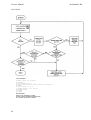
6.1 Basic checks..............................................................................................................................44
6.1.1 First, check the obvious ...........................................................................................44
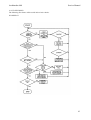
6.1.2 Flowcharts..................................................................................................................45
6.2 Run the Archimedes 440 Functional Test ............................................................................47
6.3 Main PCB faults.......................................................................................................................47
6.3.1 Video failure ..............................................................................................................47
6.3.2 System failure ............................................................................................................47
6.3.3 Unstable or scrolling display ..................................................................................48
6.3.4 Corrupted display ....................................................................................................48
6.3.5 Colours incorrect or missing ...................................................................................48
6.4 Peripheral area faults..............................................................................................................49
6.4.1 Keyboard and Mouse ...............................................................................................49
6.4.2 Floppy Disc Drive .....................................................................................................49
6.4.3 Printer .........................................................................................................................49
6.4.4 Serial port...................................................................................................................49
6.4.5 Audio ......................................................... .............................................................49
6.4.6 Configuration, non-volatile memory and real time clock ..................................49
6.5 Podules .....................................................................................................................................50
6.6 Keyboard ..................................................................................................................................50
6.6 Audio ........................................................................................................................................50
6.8 Test ROMs ................................................................................................................................50
7. Appendices............................................................................................................................................54
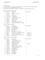
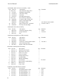
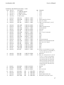
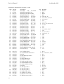
7.1 Parts Lists .................................................................................................................................55
7.2 Production and Field Changes..............................................................................................61
7.3 Archimedes Serial Port - Application Note.........................................................................63
7.4 Test Instructions ......................................................................................................................65
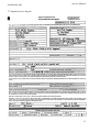
7.5 Sample Service Report............................................................................................................95
7.6 Function Map...........................................................................................................................97
7.7 Plugs and Sockets....................................................................................................................99
7.8 Links and Test Points ...........................................................................................................101
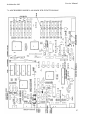
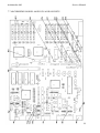
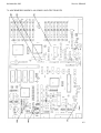
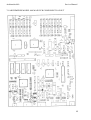
7.9 Main PCB Component Layout ............................................................................................103
7.10 Final Assembly Drawing ...................................................................................................105
7.11 Lower Case Assembly Drawing .......................................................................................107
7.12 Main PCB Circuit Diagram................................................................................................109
7.13 440 4-Way Backplane Circuit Diagram ............................................................................113
7.14 MIDI Podule Circuit Diagram...........................................................................................115
7.15 Econet Module Circuit Diagram.......................................................................................117
3
Service Manual
Archimedes 440
WARNING: THIS COMPUTER MUST BE EARTHED
Important: The wires in the mains lead for the computer are coloured in accordance with the following code:
Green and yellow
Earth
Blue
Brown
Neutral
Live
For United Kingdom users
The moulded plug must be used with the fuse and fuse carrier firmly in place. The fuse carrier is of the same basic colour (though
not necessarily the same shade of that colour) as the coloured insert in the base of the plug. Different manufacturers' plugs and fuse
carriers are not interchangeable. In the event of loss of the fuse carrier, the moulded plug MUST NOT be used. Either replace the
moulded plug with another conventional plug wired as described below, or obtain a replacement fuse carrier from an Acorn
Computers' authorised dealer. In the event of the fuse blowing it should be replaced, after clearing any faults, with a 5-amp fuse
that is ASTA approved to BS1362.
For all users
If the socket outlet available is not suitable for the plug supplied, either a different lead should be obtained or the plug should be cut
off and the appropriate plug fitted and wired as noted below. The moulded plug which was cut off must be disposed of as it would
be a potential shock hazard if it were to be plugged in with the cut off end of the mains cord exposed.
As the colours of the wires may not correspond with the coloured markings identifying the terminals in your plug, proceed as
follows:
The wire which is coloured green and yellow must be connected to the terminal in the plug which is marked by one of the
following: the letter E, the safety earth symbol, the colour green, or the colour green and yellow.
The wire which is coloured blue must be connected to the terminal which is marked with the letter N, or coloured black.
The wire which is coloured brown must be connected to the terminal which is marked with the letter L, or coloured red.
GUIDELINES FOR SAFE OPERATION
The equipment described in this guide is designed and manufactured to comply with International safety standards IEC65 (BS415)
and IEC380 (BS5850, and is intended for use only as a desktop microcomputer. It should not be used for other purposes. It is most
i mportant that unpacking and installation is carried out in accordance with the instructions given in the Welcome Guide.
The equipment is robustly constructed but in the interests of continued safe and reliable operation, careful handling and the
following guidelines should be observed.
-
DO keep the machine within a room temperature of 5 to 35 degrees C (41 to 95 degrees Fahrenheit) and a relative
humidity of 15% to 95% (non-condensing).
DO avoid sudden extremes in temperature, exposure to direct sunlight, heat sources (such as an electric fan heater) and
rain.
DO make sure that the equipment is standing on a suitable horizontal flat surface, allowing enough space for air to
circulate when the equipment is in use.
-
DO ensure that wires and cables are routed sensibly so that they cannot be snagged or tripped over. Don't tug or twist
any wires or cables, or use them to hang or lift any of the units.
-
DO switch off and unplug the equipment and any accessories before opening any unit, to install an upgrade, for example.
The main computer unit should normally be operated with the cover attached, but it can safely be switched on with the
cover removed, provided that care is taken not to short circuit any connections or to allow any fingers or objects in the
area of the fan or disc drives when these are running. Be especially careful with jewellery. Do not attempt to open any
display or monitor unit, whether supplied with this equipment or not.
DO make sure you have read and understood any installation instructions supplied with upgrade kits before attempting
to fit them. If you have any doubts, contact your supplier.
-
DON'T spill liquids on the machine. If liquid does spill, turn the machine off immediately and take it to your dealer for
assessment.
-
DON'T drop the equipment or subject it to excessive bumping and jarring. This is particularly important if you have a
hard disc installed.
-
DON'T poke objects through the ventilation openings in the computer casing, and don't let items such as necklaces or
bracelets drop into the openings.
-
DON'T exceed a maximum power consumption of 20 watts from the Podule backplane supply.
DON'T balance any objects or stand other equipment not designed for the purpose, on top of this equipment.
4
Archimedes 440
Service Manual
1. Introduction
1.1.Nature and purpose of this manual
This manual is intended to provide the information required to diagnose and rectify faults in the
Archimedes model 440 high performance computer system.
The information contained in this manual is aimed at service engineers and Acorn dealers who will be
servicing the Archimedes model 440 computer on behalf of Acorn Computers Limited.
Details of service policy are as specified by Acorn Computers Limited in the Service and Support
Strategy document.
Reference should be made to the Appendix at the back of this manual for latest Production and Field
Change information prior to servicing.
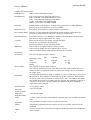
1.2.Technical Specification
GENERAL
A high performance microcomputer system, using the Acorn ARM RISC chip set, comprising the ARM
(2g) processor, the MEMC memory controller, the VIDC Video/Sound controller, and the IOC
Input/Output controller.
The 'three-box' system comprises:
A metal cased main unit, with plastic front and rear mouldings, housing the main PCB, a 1 Mbyte
(unformatted) 3.5" floppy disc drive, a fan, the PSU and a four-position backplane to provide for
expansion Peripheral Modules (Podules). The model 440 has 4 Mbytes of DRAM and a 20 Mbyte hard
disc drive. A second hard disc interface connector is provided for attachment of an additional external
(separately powered) hard disc unit.
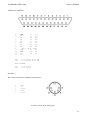
A keyboard unit with system reset button, housed in a plastic case. Connection to the main unit is via a
coiled-style serial cable and 6-way miniature circular plug. Function keystrips can be accommodated in a
tilting keystrip holder. The keyboard incorporates electronics for key scanning, mouse signal decoding
and serial data transfer between the keyboard and computer main unit. An electronically readable 6 bit
identification code is included in the keyboard to allow the computer to detect keyboard variants, such as
foreign language versions.
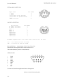
A three-button 'mouse' pointing device connects to the system via a 9-way circular socket on the
keyboard. The mouse uses two quadrature encoded signals for each axis of movement with a resolution
of 10 edges per mm. In Mode 0, 64mm of movement traverses the display area - scaling set
to 1.
The Archimedes model 440 may be supplied with one of four monitor options:
a.
No monitor
Standard Monochrome - analogue with 256 display lines at 50 Hz (TV format). This output is
b.
selected by internal links as an alternative to the Hi-res Monochrome output.
c.
Hi-res Monochrome - 0.7 V 75 52 two-level video with separate 0.3 V composite sync. signal via 2
BNC sockets. Required for:
i)
Mode 22 (1280 x 976 - graphics and text)
ii)
Mode 23 (1152 x 864 - text only)
d.
Standard Colour - 0.7 V 7552 analogue RGB with 256 display lines at 50 Hz (TV format).
Modes 0-17.
Colour - analogue RGB multi-sync type. Monitors automatically lock on to a choice of display
e.
frequencies generated by the 440:
i) TV format, 256 display lines, 50 Hz non-interlaced, modes 0-17.
ii) High resolution mode, 512 display lines, 50 Hz non-interlaced, modes 18-20.
NB Colour composite video and UHF/VHF TV outputs are not provided.
5
Archimedes 440
Service Manual
COMPUTER MAIN UNIT
4 Mbyte with 32 kb RAM per `page'.
RAM Memory
Four 32 pin sockets are fitted. The options are:
ROM Memory
256K - 4 off 64K x 8bit ROM/EPROM (eg 27512)
512K - 4 off 128K x 8bit ROM (eg 62301 ROM)
1024K - 4 off 256K x 8 bit ROM/EPROM
2048K - 4 off 512K x 8 bit ROM/EPROM
Processor
96 MHz master clock oscillator. 24 MHz main system clock. 4/8 MHz ARM (2u)
processor. System performance is typically 4 MIPS.
Real-time clock
Powered by internal batteries when computer switched off.
Non-volatile RAM
240 bytes of static RAM which maintains preferred machine configuration, etc.
Powered by internal batteries while the computer is switched off.
Internal batteries
Two LR06 (AA size) 1.5 V Manganese Alkaline cells fitted inside computer main
unit. Batteries require replacement once a year.
Controls
Mains on/off switch at rear of unit, integral with PSU.
Floppy disc eject button(s) on front panel.
System reset button (on rear of keyboard unit).
Indicators
Green LED on front panel indicates mains power on.
Amber LED on floppy disc drive indicates drive activity.
Amber LED below power LED indicates hard disc drive activity.
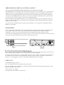
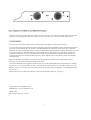
Connectors
Power inlet
IEC 320/CEE 22 power inlet connector.
Operating voltage
range
Frequency
Rating
Power Outlet
Min.
Nominal
198
47
220/240
50/60
70
Max.
264 Vac
63 Hz
VA
IEC 320/CEE 22 power outlet connector.
This outlet is unswitched (ie not controlled by the PSU on/off switch) and is live
whenever power is applied to the power inlet. Power rating 3 A max. continuous,
80 A max. surge.
Podule Bus
A four position backplane is fitted as standard via a 96-way DIN 41612 connector to
the main PCB. The backplane is fitted with four Podule connectors. Three of these
are 64-way DIN 41612 connectors (connector rows a and c only loaded), into which
any suitable non-coprocessor Podules may be plugged. The remaining connector is
a 96-way with all rows a, b, and c loaded, into which any Podules including a
coprocessor can be plugged.
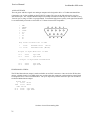
Parallel printer
25-way D type socket.
Serial port
9-way D type plug.
Colour analogue
RGB video
9-way D type socket.
High Resolution
Video
2 x BNC (Video and Sync). Monochrome composite video also available via internal
links.
Keyboard
6-way miniature circular socket for keyboard connection.
Mouse
Three-button mechanical mouse connects via a 9-way circular connector on the
keyboard.
Audio
3.5 mm 32 ohm stereo jack socket for output to suitable personal-stereo headphones
or hi-fi system.
6
Service Manual
Archimedes 440
DIMENSIONS
Main Unit
Overall height - 97 mm (excluding feet)
Overall width - 362 mm approx.
Overall depth - 406 mm approx.
Colour
Two-tone cream/ warm grey
Finish
Fine texture
Materials
Painted metal
ABS, flame retardent to meet IEC 950
Keyboard
Overall height - 46 mm (excluding feet)
Overall width - 485 mm
Overall depth - 205 mm
Colour
Cream case with warm grey keys (in two shades).
Finish
Fine texture.
Case material
ABS, flame retardent to meet IEC950
Function keystrip
holder
Clear plastics flame retardent to meet IEC 950.
Weight:
8.1 Kg
OPTIONS - (see Upgrading, section 4, for fitting details)
Plug-in Econet module fits onto main PCB. Econet 5-pin DIN socket fitted as
Econet interface
standard (may be fitted with blanking plug prior to upgrade).
Podules
ROM Podule
(AKA05)
Up to four Podules can be fitted. Without an Econet module fitted, the machine can
have up to four single, or two double-width Podules fitted. These are mechanically
identical to single or double Eurocards. The Podules are fitted side by side and/or
one above the other at the rear of the computer. If an Econet module is fitted, a halfwidth only Podule (or one designed to fit around an Econet module, such as the
1/O Podule) can be fitted in the lower position. The 440 can be fitted with any of the
four categories of Podule - simple, MEMC, External and, in slot 2 only, a
coprocessor Podule. Podules available and planned for the Archimedes system
include:
Provides a capability for plug-in ROM based software.
I/O Podule (AKA10) Reproduces the BBC Model B/Master Series A to D port, User Port and 1 MHz bus.
MIDI Podule
(AKA16)
Provides a MIDI control interface with music synthesisers.
A MIDI module, AKAl5, which can be added to an I/O Podule, is also available.
Ethernet
Provides a basic connection to an Ethernet network.
FP Co-processor
Provides a hardware floating point coprocessor capability.
ENVIRONMENTAL
Operating
Temperature
5 to 35° C
Humidity
10% to 95% at 35° C non-condensing
Altitude
0 to 2500 metres above sea level
Storage
Temperature
-40 to 70° C
Humidity
10 to 95% RH non-condensing
Altitude
Up to 10,000 metres
7
Service Manual
Archimedes 440
ELECTRICAL SAFETY
Designed, manufactured and tested to comply with the EEC Low Voltage Directive.
When fitted with PSU intended for 220/240 V operation:
BS415
BS5850
(IEC 65)
(IEC 380)
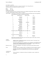
OPERATING SYSTEM
The Arthur Operating System is described in detail in the Archimedes Programmers' Reference Manual.
A summary of the facilities offered by Arthur is as follows:
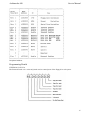
Screen modes
Twenty-three screen modes are supported. The first eight modes provide compatibility
with the BBC Microcomputer 6502 based range MOS:
Text
Mode
Pixel Resolution
Logical Colours
0
640 x 256
2
1
320 x 256
4
2
160 x 256
16
3
TEXT ONLY
2
4
320 x 256
2
5
160 x 256
4
6
TEXT ONLY
2
7
TELETEXT
TELETEXT
8
640 x 256
4
9
320 x 256
16
10
160 x 256
256
11
TEXT ONLY
80 x 25
12
640 x 256
16
13
320 x 256
256
TEXT ONLY
14
16
15
640 x 256
256
16
TEXT ONLY
16
17
TEXT ONLY
16
The following modes are for use with multi-sync monitors only:
18
640 x 512
2
19
640 x 512
4
20
640 x 512
16
Hi-resolution monochrome modes:
22
1280 x 976
2
23
1152 x 864
2
80 x 32
40 x 32
20 x 32
80 x 25
80 x 25
20 x 32
40 x 25
40 x 25
80 x 32
40 x 32
20 x 32
80 x 32
40 x 32
80 x 25
80 x 32
132 x 32
132 x 25
80 x 64
80 x 64
80 x 64
160 x 122
144 x 54
In all modes except Teletext, the colours can be chosen from a palette of 4096 colours, with some
restrictions in the 256 colour modes.
Graphics
Extensions
Modes 16 and 17, together with graphics extensions, enable VT 100 and VT 220
emulations to be implemented.
The GCOL primitive has been extended to cover transparency and additional raster
operations. The GXR Sprite function has been extended to support WIMPS more
fully and to provide BUTTER functions for animation.
Hardware cursor
This is a user-definable 3 colour shape (a sprite) which can be linked to mouse
movement.
Fonts
Alternative fonts are supported. These are defined in a file and cached as required
in memory. The fonts are proportionally spaced and can cover a wide range of
point sizes. Options for text justification are provided for use by application
programs.
Command line
interpreter
8
Allows parameters, conditionals, aliasing of commands, system variables and
expressions.
Service Manual
Archimedes 440
Debug facilities
A Monitor program is provided which allows for debugging, ie breakpoints,
disassembler, etc.
Sound
Extended features are provided to support the hardware capability.
The Operating System sound code is split into three levels:
Level 0
Sound DMA Buffer handler:
Number of channels, sample rate, channel length.
Program number of channels (max. of 8 - default 1)
Enable/disable local speaker
Enable/disable sound system
Program stereo position (max. of 7 positions)
Level 1
Sound Channel Controller:
Sets loudness amongst many other characteristics.
Level 2
Event Queue manager:
Schedules events related to screen display, etc.
BBC BASIC V
Contains extended functions, including:
ENDWHILE
WHILE
OTHERWISE
ENDCASE
CASE - WHEN
ELSE
ENDIF
IF
THEN
Function and Procedure libraries
Enhanced error handling
Whole array operations
Binary and unary operators
Enhanced TRACE
Improved PRINT accuracy
Re-written string storage
More line numbers and sophisticated tabulation
Full ARM assembler
BASIC editor
6502 Emulation
Code
Advanced Disc
Filing System
Advanced Network
Filing System
An extended version of the Acornsoft 6502 based editor.
This code, which is supplied on the Welcome disc, provides a software
environment in which to execute legally' written 6502 code.
An improved version of the 6502-based ADFS. User disc handling has been both
extended and simplified. An additional 800K disc format is added which also
provides a faster access time.
An improved version of the 6502-based ANFS, it has been generalised to support a
broader Networking base. Three code modules are included: Econet, NetFS and
NetPrint.
1.3 Packaging and Installation
The computer main unit, keyboard and mouse are supplied in a moulded two-part polystyrene packing
in a cardboard carton. Also included are a Welcome Guide, a Welcome/Utilities disc, a User Guide, a
Keycard set and a guarantee card. An optional colour or monochrome monitor is supplied packed
separately.
Do not use the computer system in conditions of extreme heat, cold, humidity or dust or in places subject
to vibration. Do not block the ventilation slots in the main unit casing. Ensure that no foreign objects are
inserted through any openings in the casing.
9
Service Manual
Archimedes 440
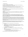
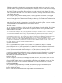
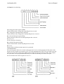
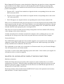
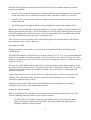
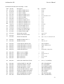
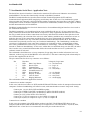
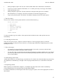
2. System Description
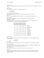
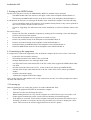
Introduction
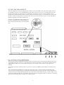
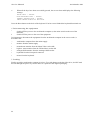
The Archimedes computers are built around the A Series chip set, comprising the Acorn Risc Machine
(ARM), the Memory Controller (MEMC), Video Controller (VIDC) and Input Output Controller (IOC).
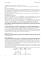
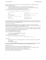
A schematic of the Archimedes model 440 is shown below:
General
The ARM (Acorn Risc Machine) IC is a pipelined, 32 bit reduced instruction set microprocessor which
accepts instructions and manipulates data via a high speed 32 bit data bus and 26 bit address bus giving a
64 MByte uniform address space. The ARM supports virtual memory systems using a simple but
powerful instruction set with good high-level language compiler support.
The Memory Controller (MEMC) acts as the interface between the ARM, the Video Controller, I/O
Controllers, Read-Only Memory (ROM) and Dynamic memory devices (DRAM), providing all the
critical system timing signals including processor clocks.
4 MByte of DRAM is connected to MEMC which provides all signals and refresh operations. A Logical to
Physical Translator maps the Physical Memory into a 32 MByte Logical address space (with three levels
of protection) allowing Virtual Memory and Multi-Tasking operations to be implemented. Fast 'page
mode' DRAM accesses are used to maximise memory bandwidth. The VIDC requests data from the RAM
when required and buffers it in one of three FIFOs before using it. Data is requested in blocks of four 32bit words, allowing efficient use of paged-mode DRAM without locking the system data bus for long
periods.
MEMC supports Direct Memory Access (DMA) operations with a set of programmable DMA Address
Generators which provide a circular buffer for Video data, a linear buffer for Cursor data and a double
buffer for Sound data.
The Video Controller (VIDC) takes video data from memory under DMA control, serialises it and passes
it through a colour look-up palette and converts it to analogue signals for driving the CRT guns. The
10
Archimedes 440
Service Manual
VIDC also controls all the display timing parameters and controls the position and pattern of the cursor
sprite. In addition, it incorporates an exponential Digital to Analogue Converter (DAC) and stereo image
table for the generation of high quality sound from data in the DRAM.
The VIDC is a highly programmable device, offering a very wide choice of display formats. The colour
l ook-up palette which drives the three on-chip DACs is 13 bits wide, offering a choice from 4096 colours
or an external video source.
The cursor sprite is 32 pixels wide and any number of rasters high. Three simultaneous colours (again
from a choice of 4096) are supported and any pixel can be defined as transparent, making possible
cursors of many shapes. It can be positioned anywhere on the screen. The sound system implemented on
the device can support up to 8 channels, each with a separate stereo position.
The Input Output Controller (IOC) controls the IO bus, expansion Podules and provides basic functions
such as the keyboard interface, system timers, interrupt masks and control registers. It supports a number
of different peripheral cycles and all IO accesses are memory mapped.
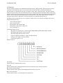
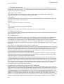
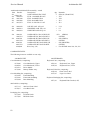
The I/O system
The 1/O system is controlled by the I/O Controller IOC and the Memory Controller MEMC. The I/O Bus
supports all the internal peripherals and the PODULE expansions. Details of the expansion bus can be
found elsewhere in this manual.
This section presents details of the I/O system for particular versions of the Archimedes series. It is intended to give
the reader an understanding of Archimedes computers and should not be used to program the 1/O system directly.
The implementation details are liable to change at any time and only the published software interfaces should be
used to manipulate the I/O system. It is important to realise that future systems may have a different
implementation of the I/O system, and in particular the addresses (and number) of Podule locations may move. For
this reason, and to ensure that any device may be plugged into any slot, all driver code for Podules must be
relocatable. References to the direct Podule addresses should never be used. It is up to the machine operating system,
in conjunction with the Podule ID, to determine the address at which a Podule should be accessed. To this extent,
some of the following sections are for background information only.
System Architecture
The 1/O system (which includes podule devices) consists of a 16 bit data bus (BD[0:151) a buffered
address bus (LA[2:211) and various control and timing signals. The 1/O data bus is independent from the
main 32-bit system data bus, being separated from it by bidirectional latches and buffers. In this way the
I/O data bus can run at much slower speeds than the main system bus to cater for slower peripheral
devices. The latches between the 2 buses and hence the 1/O bus timing are controlled by the I/O
controller, IOC. The IOC caters for 4 different cycle speeds (slow, medium, fast and synchronous).
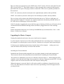
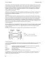
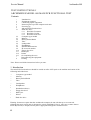
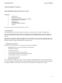
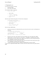
A typical I/O system with Podules fitted is shown in the diagram on page 12. The Podules are controlled
by IOC, and the MEMC Podules share the I/O Controller interface with IOC. For clarity, the data and
address buses are omitted from this diagram.
NON-IOC DEVICES
The IOC is mapped to control devices in the upper half of the I/O space. The lower half of the I/O space
may be used by opther devices which are not mapped through, or timed by theIOC. Such devices
(normally MEMC Podules) share the same handshaking control lines to the MEMC as does the IOC. The
advantage of devices in this class are that they are not tied to one of the four possible IOC cycle types.
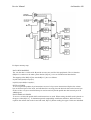
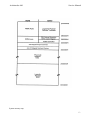
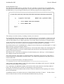
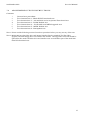
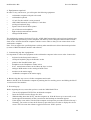
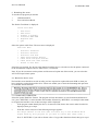
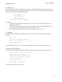
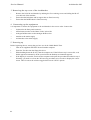
SYSTEM MEMORY MAP
The system memory map is defined by the MEMC, and is shown on page 13. Note that all system
components, including I/O devices, are memory mapped.
I/O SPACE MEMORY MAP
This IOC-controlled space has allocation for Simple Podules and External Podules.
11
Service Manual
Archimedes 440
I/O Space memory map
DATA BUS MAPPING
The 1/O data bus is 16 bits wide. Bytewide accesses are used for 8-bit peripherals. The 1/O data bus
(BD[0:151) connects to the main system data bus (D[0:31]) via a set of bidirectional data latches.
The mapping of the BD[0:15] bus onto theD[0:31] bus is as follows:
During a WRITE (ie ARM to peripheral)BD[0:151 is mapped toD[16:31].
During a READ (ie peripheral to ARM)BD[0:151 is mapped toD[0:15]
BYTE ACCESSES
To access bytewide podules, byte instructions are used. A byte store instruction will place the written
byte on all four bytes of the word, and will therefore correctly place the desired value on the lowest byte
of the 1/O bus. A byte or word load may be used to read a bytewide podule into the lowest byte of an
ARM register.
HALF-WORD ACCESSES
To access a 16-bit wide podule, half-word instructions are used. When storing, the half-word is placed on
the upper 16 bits,D[16:31]. To maintain upwards compatibility with future machines, half-word stores
replicate the written data on the lower half-word, D[0:15]. When reading, the upper 16 bits are undefined.
12
Archimedes 440
Service Manual
System memory map
13
Service Manual
Archimedes 440
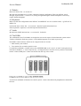
PODULE IDENTIFICATION
It is important that the system is able to identify what podules (if any) are present, and where they are.
This is done by reading the Podule Identification (PI) byte, or bytes, from the Podule Identification Field.
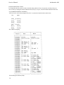
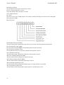
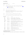
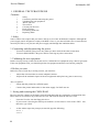
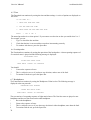
I/O ADDRESS MEMORY MAPPING
All I/O accesses are memory mapped. The IOC is connected as detailed in the table below:
IOC
ARM
[OE] _ [LA[21]]
[T[1]] _
[LA[20]]
[T[0]] _
[LA[19]]
[B[2]] _ [LA[18]]
[LA[17]]
[B[1]] _
[B[0]] _
[LA[16]]
IOC address mapping
Internal Register Memory Map
14
Archimedes 440
Service Manual
Peripheral address
Programming Details
EXTERNAL LATCH A
The External Latch A is a write only latch used to control parts of the floppy disc sub-system.
15
Service Manual
Archimedes 440
Bit [031 US [0:31
These bits select the floppy disc unit 0 through 3 when written LOW. Only one bit should be LOW at any
one time.
Bit 4 Side Select
This control the side select line of the floppy disc interface.
0 = Side 1 (upper)
1 = Side 0 (lower)
Bit 5 Floppy Motor ON/OFF Control
This bit control the floppy disc motor line. Its exact use depends on the type of drive.
Bit 6 In Use
This bit controls the INUSE line of the floppy disc. Its exact use depends on the type of drive.
Bit 7 Disc Eject
This controls the DISC EJECT or DISC CHANGED RESET line of the floppy disc drive.
EXTERNAL LATCH B
The External Latch B is a write only register shared between several users who must maintain a
consistent RAM copy. Updates must be made with IRQ disabled.
Bit [0:21 CD [0:21
CD[0:21 should be programmed LOW for future compatibility. CD [1] controls the floppy disc data
separator format.
CD[11 = 1
CD[1]=0 Double Density
Single Density
Bit 3 FDCR
This controls the floppy disc controller reset line. When programmed LOW, the controller is RESET.
Bit 4 Printer Strobe
This used to indicate valid data on the printer outputs. It should be set HIGH when valid data has been
written to the printer port and LOW after typically 5 usec.
Bit [5:61 AUX [1:21
These bits allow the auxiliary I/O connector AUX [1:21 pins to be programmed.
Bit 7 HS3
This bit controls the HS3 line of the hard disc interface. It allows extension of the ST506 interface to
support up to 16 heads. It may be link selected to implement the standard ST506 "Reduced Write
Current" function.
16
Archimedes 440
Service Manual
INTERRUPTS
The I/O system generates two independent interrupt requests, IRQ and FIQ. Interrupt requests can be
caused by events internal to IOC or by external events on the interrupt or control port input pins.
The interrupts are controlled by four types of register, status, mask, request and clear. The status registers
reflect the current state of the various interrupt sources. The mask registers determine which sources may
generate an interrupt. The request registers are the logical AND of the status and mask registers and indicate
which sources are generating interrupt requests to the processor. The clear register allows clearing of
interrupt requests where appropriate. The mask registers are undefined after power up.
The IRQ events are split into two sets of registers A and B. There is no priority encoding of the sources.
Internal Interrupt Events
•
•
•
•
•
Timer interrupts TM[0:11
Power-on reset POR
Keyboard Rx data available SRx
Keyboard Tx data register empty STx
Force interrupts "1"
External Interrupt Events
•
•
•
•
•
•
IRQ active low inputs IL[0:7] wired as PFIQ SIRQ WIRQ DCIRQ, PIRA PBSY and RII.
IRQ falling-edge input IF wired as PACK
IRQ rising-edge iput IR wired as VFLY
FIQ active high inputs FII[0:11 wired as FFDQ and FFIQ
FIQ active low input FL wired as EFIQ
Control port inputs C[3:51
IRQ STATUS A
Bit 0 PBSY
This bit indicates that the printer is busy.
Bit 1 RII
This bit indicates that a Ringing Indication has been detected by the serial line interface.
Bit 2 Printer Acknowledge
This bit indicates that a printer acknowledgement bit has been received.
Bit3 Vertical Flyback
This bit indicates that a vertical flyback has commenced.
17
Service Manual
Archimedes 440
Bit 4 Power-on Reset
This bit indicates that a power-on reset has occured.
Bit [5:61 Timer 0 and Timer 1 events
These bits indicate that events have occurred.
Note: latched interrupt.
Bit 7 Force
This bit is used to force an IRQ request. It is usually owned by the FIQ owner and is used to downgrade
FIQ requests into IRQs.
IRQ STATUS B
Bit 0 Podule FIQ request (PFIQ)
This bit indicates that a Podule FIQ request has been received. It should usually be masked OFF.
Bit 1 Sound buffer swap (SIRQ)
This bit indicates that the MEMC sound buffer pointer has been relocated.
Bit 2 Serial line controller (SLCI)
This bit indicates that 65C51 serial line controller interrupt has occurred.
Bit 3 Winchester interrupt
This bit indicates that a Winchester (Hard disc) interrupt has occurred.
Bit 4 Disc Changed Interrupt (DCIRQ)
This bit indicates that the floppy disc has been removed.
Bit 5 Podule interrupt request (PIRQ)
This bit indicates that a Podule IRQ request has occurred.
Bit 6 Keyboard transmission event
This bit indicates that the keyboard transmit register is empty and may be reloaded.
Bit 7 Keyboard reception event
This bit indicates that the keyboard reception register is full and may be read.
18
Archimedes 440
Service Manual
INTERRUPT STATUS FIQ
Bit 0 Floppy disc data request (FFDR)
This bit indicates that a Floppy Disc Data Request has occurred.
Bit 1 Floppy disc interrupt request (FFTIQ)
This bit indicates that a Floppy Disc Interrupt Request has occurred.
Bit 2 Econet Interrupt request (EFIQ)
This bit indicates that an Econet Interrupt Request has occurred.
Bit [3:51 C[3:51
See IOC data sheet for details.
Bit 6 Podule FIQ request (PFIQ)
This bit indicates that a Podule FIQ Request has occurred.
Bit 7 Force
This bit allows an FIQ interrupt request to be generated.
CONTROLPORT
The control register allows the external control pins C[0:51 to be read and written and the status of the
PACK and VFLY inputs to be inspected. The C[0:51 bits manipulate the C[0:511/0 port. When read, they
reflect the current state of these pins. When written LOW the output pin is driven LOW. These outputs
are open-drain, and if programmed HIGH the pin is undriven and may be treated as an input.
On reset all bits in the control register are set to "1".
19
Service Manual
Archimedes 440
C[7](VFLYBK) and Test Mode
C[71 allows the state of the (VFLYBK) signal to be inspected. This bit will be read HIGH during vertical
flyback and LOW during display. See VIDC datasheet for details. This bit MUST be programmed HIGH
to select normal operation of the chip.
C[6] (PACK) and Test Mode
C[61 allows the state of the parallel printer acknowledge input to be inspected. This bit MUST be
programmed HIGH to select normal operation of the the chip.
C[5] (SMUTE)
This controls the muting of the internal speaker. It is programmed HIGH to mute the speaker and LOW
to enable it. The speaker is muted on reset.
C[4] (C4)
C[41 is available on the Auxiliary I/O connector.
C[3]
C[31 is reserved and should be programmed HIGH.
C[2] (READY)
C[21 is used as the floppy disc (READY) input and must be programmed HIGH.
C[1:0] SDA, SCL The IIC Bus
The C[0:1] pins are used to implement the bi-directional serial I 2C bus to which the Real Time Clock and
battery RAM are connected.
The Sound System
The sound system is based on the VIDC stereo sound hardware. External analogue anti-alias filters are
used which are optimised for a 20 kHz sample rate. The high quality sound output is available at a
3.5mm stereo jack socket at the rear of the machine which will directly drive personal-stereo headphones
or alternatively an amplifier and speakers. A mono mix of the sound output is sent to the internal
loudspeaker. In addition, an unfiltered stereo signal is available at the Auxiliary Audio connector on the
main board.
THE VIDEO CONTROLLER SOUND SYSTEM HARDWARE
VIDC contains an independent sound channel consisting of the following components: A four-word FIFO
buffers sixteen 8-bit sound samples with a DMA request issued whenever the last byte is consumed from
the FIFO. The sample bytes are read out at a constant sample rate programmed into the 8-bit Audio
Frequency Register which may be programmed to allow samples to be output synchronously at any
integer value between 3 and 255 microsecond intervals.
The sample data bytes are treated as sine plus seven-bit logarithmic magnitude and after exponential
digital to analogue conversion, de-glitching and sign-bit steering, are output as a current at one of the
audio output pins to be integrated and filtered externally.
VIDC also contains a bank of eight stereo image position registers each of 3 bits. These 8 registers are
sequenced through at the sample rate with the first register synchronised to the first byte clocked out of
the FIFO. Every sample time is divided into eight time slots and the three bit image value programmed
for each register is used to pulse width modulate the output amplitude between the LEFT and RIGHT
audio current outputs in multiples of time slot subdivisions. This allows the signal to be spatially
positioned in one of seven stereo image positions.
THE MEMORY CONTROLLER SOUND SYSTEM HARDWARE
MEMC provides three internal DMA address registers to support Sound buffer output; these control the
DMA operations performed following Sound DMA requests from VIDC. The registers allow the physical
addresses for the START, PNTR (incremental) and END buffer pointers to a block of data sample in the
l owest half Megabyte of physical RAM to be accessed. These operate as follows: programming a 19-bit
address into the PNTR register sets the physical address from which sequential DMA reads will occur (in
multiples of 4 words) and programming the END pointer sets the last physical address of the buffer.
Whenever the PNTR register increments up to this END value the address programmed into the START
register is automatically written into the PNTR register for the DMA to continue with a new sample
20
Archimedes 440
Service Manual
buffer in memory. A Sound Buffer Interrupt (SIRQ) signal is generated when the reload operation occurs
which is processed by IOC as a maskable interrupt (IRQ) source.
The Memory Controller also includes a sound channel enable/disable signal. Because this enable/disable
control signal is not synchronised to the sound sampling requests will normally be disabled after the
waveforms which are being synthesised have been programmed to decay to zero amplitude; the last
value loaded into the Audio data latch in the VIDC will be output to each of the Stereo image positions at
the current Audio Sample rate.
THE I/O CONTROLLER SOUND SYSTEM HARDWARE
I OC provides a programmed output control signal which is used to turn the internal speaker on or off, as
well as an interrupt enable/status/reset register interface for the Sound Start Buffer reload signal
generated by the Memory Controller.
The internal speaker may be muted by the control line SMUTE which is driven from the IOC output C5.
On reset this signal will be taken high and the internal speaker will be muted.
The stereo output to the Hi-Fi stereo output is not muted by SMUTE and will always reflect the current
output of the DAC channels.
The Keyboard
The ARM to keyboard connection is essentially a half duplex connection with handshaking by the ARM,
plus a small amount of command protocol by the ARM. When the keyboard has sent a byte, in normal
operation, it will not send again until it has received an Ack from the ARM. The only exception to this is
during the reset protocol used to synchronise the handshaking, where each side is expecting specific
responses from the other, and will not respond further until it has those.
In addition to this simple handshaking system, the keyboard will not send mouse data unless specifically
allowed to, as indicated by Ack Mouse, which allows the transmission of one set of accumulated mouse
coordinate changes, or the next move made by the mouse. While it is not allowed to send mouse changes
the keyboard will buffer mouse changes.
A similar handshake exists on key changes, transmitted as key up and key down, and enabled by Ack
Scan. At the end of a keyboard packet (two bytes) ARM should always perform an Ack Scan as there is no
protocol for re-enabling later. With the mouse, the ARM may request mouse data some time later by
means of Request Mouse Position (RQMP)
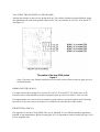
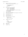
KEY CODES
The keyboard identifies each key by its row and column address in the keyboard matrix. Row and
column codes are appended to the key up or down prefix to form the complete key code.
e.g. 'Q key down, the complete row code is 11000010 (C2 hex) and the column code is 11000111 (C7 hex).
Note: Eight keys have N key roil over.The ARM is responsible for implementing 2key rollover, therefore
the keyboard transmits all key changes (when enabled). The keyboard does not operate any auto-repeat,
only one down code is sent, at the start of the key down period.
Operating voltage range (measured at the cable plug) is 5 V ±0.5 V. Maximum current consumption of the
of the keyboard is 60 mA (note that the mouse may use up to an additional 100 mA).
A maximum delay of IOOms is permissible from release of the reset switch to the first keyboard
transmission of HRST.
SERIAL INTERFACE
Information on the keyboard status is sent to the ARM via a serial data link using NRZ encoding.
Command and acknowledge codes are similarly sent from the computer to the keyboard along a serial
data link. The two links form a full duplex system which operates at 31.25 k baud. Each data byte (eight
data bits) is preceded by a single start bit (logic 1). The least significant data bit (DO) is sent first. The last
data bit (D7) is followed by two stop bits (logic 0). Note that data is sent in inverted form, that is a logic 1
data bit will appear on the serial line as a logic 0 and vice versa.
When idle the line is held at a logic O level.
21
Service Manual
Archimedes 440
Serial INPUT/OUTPUT characteristics
Serial line signals are CMOS compatible. The data line logic input has a nominal switching threshold of
50% of the supply voltage, to minimise skew between rising and falling edges. Signal hysteresis is
provided on input lines, to minimise noise susceptibility.
SERIAL DATA PROTOCOL
Serial data transmissions from the keyboard are either one or two bytes in length. Each byte sent is
individually acknowledged by the ARM. The keyboard will not transmit a byte until the previous byte
has been acknowledged, unless it is the HRST code indicating that a power on or user reset occurred or
that a protocol error occurred; see below.
Reset Protocol
The keyboard restarts when it receives a HardReSeT (HRST) code from the ARM. To initiate a restart the
keyboard sends a HRST code to the ARM, which will then send back HRST to command a restart. The
keyboard sends HRST to the ARM if
A power on reset occurs
A User reset occurs
A protocol error is detected
After sending HRST, the keyboard waits for a HRST code. Any non HRST code received causes the
keyboard to resend HRST. The pseudo program below illustrates the reset sequence or protocol.
START reset
ONerror Send HRST code to ARM then wait for code from ARM.
IF code = HRST THEN restart ELSE error
ONrestart
clear mouse position counters
set mouse mode to data only in response to an RMPS request.
stop key matrix scanning and set key flags to up
send HRST code to ARM
Wait for next code
IF code = RAK1 THEN send RAK1 to ARM
ELSE
error
Wait for next code
IF code = RAK2 THEN send RAK2 to ARM
ELSE
error
Wait for next code
IF code = SMAK THEN mouse mode to send if not zero and enable key scan
ELSE IF code = SACK THEN enable key scanning
ELSE IF code = MACK THEN set mouse mode to send when not zero
ELSE IF code = NACK THEN do nothing
ELSE error
END reset
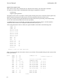
Reset sequencing
Direction
Code
ARM
Kb
ARM
Kb
ARM
->
->
->
->
->
Kb
ARM
Kb
ARM
Kb
Expected
reply
Action on
Action on
wrong reply timeout
(Sender)
( Sender)
Hard reset Hard reset Resend
Hard reset Reset Ack 1 Resend
Reset Ack 1 Reset Ack 1 Hard reset
Reset Ack 1 Reset Ack 2 Nothing
Reset Ack 2 Reset Ack 2 Hard reset
Action if
unexpected
(Receiver)
Resend
Hard reset
Nothing
Hard reset
Hard reset Hard reset
Nothing
Hard reset
Hard reset Hard reset
Note, the on/off state of the LED's does not change across a reset event, hence the LED state is not
defined at power on. The ARM is always responsible for selecting the LED status. After the reset
sequence, Key scanning will only be enabled if a scan enable acknowledge (SACK or SMAK) was
received from the ARM.
22
Archimedes 440
Service Manual
Data Transmission
When enabled for scanning, the keyboard informs the ARM of any new key down or new key up by
sending a two byte code incorporating the key row and column addresses. The first byte gives the row
and is acknowledged by a byte acknowledge (BACK) code from the ARM. If BACK was not the
acknowledge code then the error process (ONerror) is entered. If the BACK code was received the
keyboard sends the column information and waits for an acknowledge. If either a NACK, SACK, MACK
or SMAK acknowledge code is received, the keyboard continues by processing the ack. type and selecting
the mouse and scan modes implied. If the character received as the second byte acknowledge was not one
of NACK/MACK/SACK/SMAK then the error process is entered.
Mouse Data
Mouse data is sent by the keyboard if requested by a RQMP request from the ARM or if a SMAK or
MACK have enabled transmission of non-zero values. Two bytes are used for mouse position data. Byte
one encodes the accumulated movement along the X axis while byte two gives Y axis movement.
Both X and Y counts must be transferred to temporary registers when data transmission is triggered, so
that accumulation of further mouse movement can occur. The X and Y counters are cleared upon each
transfer to the transmit holding registers. Therefore, the count values are relative to the last values sent.
The ARM acknowledges the first byte (Xcount) with a BACK code and the second byte (Ycount) with
any of NACK/MACK/SACK/SMAK. A protocol failure causes the keyboard to enter the error process
(ONerror).
When transmission of non-zero mouse data is enabled, the keyboard gives Key data transmission priority
over mouse data except when the mouse counter over/underflows.
Acknowledge Codes
There are seven acknowledge codes which may be sent by the ARM. RAK1 and RAK2 are used during
the reset sequence. BACK is the acknowledge to the first byte of a two byte keyboard data set. The four
remaining types, NACK/MACK/SACK and SMAK, acknowledge the final byte of a data set. NACK
disables key scanning and therefore key up/down data transmission as well as setting the mouse mode
to send data only on RQMP request. SACK enables key scanning and key data transmission but disables
unsolicited mouse data. MACK disables key scanning and keydata transmission and enables the
transmission of mouse count values if either X or Y counts are non-zero. SMAK enables key scanning and
both key and mouse data transmission. It combines the enable function of SACK and MACK.
While key scanning is suspended (after NACK or MACK) any new key depression is ignored and will
not result in a key down transmission unless the key remains down after scanning resumes following a
SACK or SMAK. Similarly a key release is ignored while scanning is off.
Command may be received at any time. Therefore, commands can be interleaved with acknowledge
replies from the ARM, eg keyboard sends KDDA (1st byte), keyboard receives command, keyboard
receives BACK, keyboard sends KDDA (2nd byte), keyboard receives command, keyboard receives
SMACK. If the HRST command is received the keyboard immediately enters the restart sequence, see
(ONrestart). The LEDS and PRST commands may be acted on immediately. Commands which require a
response are held pending until the current data protocol is complete. Repeated commands only require a
single response from the keyboard.
23
Service Manual
Archimedes 440
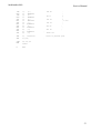
ARM COMMANDS
Function
Mnemonic
HRST
Reset keyboard
LEDS
Turns key cap LED's on/off. A three bit field indicates which
state the LED's should be in. Logic 1 is ON, logic 0 (zero)
D O controls CAPS LOCK
Dl controls NUM LOCK
D2 controls SCROLL LOCK
OFF.
RQMP
Request mouse position (X,Y counts)
RQID
Request keyboard identification code.
The keyboard is manufactured with a 6 bit code to identify the
keyboard type to the ARM. Upon receipt of RQID the keyboard
transmits KBID to the ARM
PRST
Reserved for future use, keyboard ignores this command
RQPD
For future use.The keyboard will encode the four data bits
into the PDAT code data field and then send PDAT to the ARM.
Code values
Mnemonic
msb lsb
Comments
HRST
RAK1
RAK2
RQPD
PDAT
of RQPD
RQID
KBID
KDDA
1111
1111
1111
0100
1110
One
One
One
One
One
KUDA
1101 xxxx
RAMP
MDAT
0010 0010
Oxxx xxxx
BACK
NACK
0011 1111
0011 0000
SACK
MACK
SMAK
LEDS
PRST
0011
0011
0011
0000
0010
1111
1110
1101
xxxx
xxxx
0010 0000
loxx xxxx
1100 xxxx
0001
0010
0011
Oxxx
0001
byte
byte
byte
byte
byte
command, keyboard reset
response in reset protocol
response in reset protocol
From ARM, encodes four bits of data
from keyboard, echoes four data bits
One byte ARM request for keyboard ID
One byte from keyboard encoding keyboard ID
New key down data. Encoded Row (1st byte) and
column (2nd byte) numbers
Encoded Row (1st byte) and column (2nd byte)
numbers for a new key up
One byte ARM request for mouse data
Encoded mouse count, X (bytel) then Y (byte2)
Only from ARM to keyboard
Ack for first keyboard data byte pair
Last data byte ack, selects scan/mouse mode
see 1.5.7
Last data byte ack, see 1.5.7
Last data byte ack, see 1.5.7
Last data byte ack, see 1.5.7
bit flag to turn LED's) on/off
From ARM, one byte command, does nothing
x is a data bit in the Code eg xxxx is a four bit data field
INTERCONNECTION CABLE
The interconnection cable has stranded conductors, suitable for operation at 5 V, 200 mA per conductor.
24
Archimedes 440
Service Manual
MOUSE INTERFACE
The mouse interface has three switch sense inputs and two quadrature encoded movement signals for
each of the X axis and Y axis directions. Mouse key operations are debounced and then reported to the
ARM using the Acorn key up / key down protocol. The mouse keys are allocated unused row and
column codes within the main key matrix.
Switch 1 (left)
Row code - 7
Column code - 0
Switch 2 (middle)
Row code - 7
Column code - 1
Switch 3 (right)
Row code - 7
Column code - 2
e.g. Switch 1 release would give 11010111 (D7 hex) as the complete row code, followed by 11010000 (DO
hex) for the column code.
Note: Mouse keys are disabled by NACK and MACK acknowledge codes, and are only enabled by SACK
and SMAK codes, ie they behave in the same way as the keyboard keys.
The mouse is powered from the keyboard 5 V supply and may consume up to 100 mA. The keyboard
design ensures that the power supply voltage at the mouse connector is within ±150 mV of the voltage
supplied at the keyboard cable plug. Sufficient power supply decoupling is provided to ensure that
connection and disconnection of the mouse from the keyboard does not affect normal keyboard
operation.
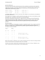
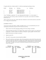
Movement Signals
Each axis of movement is independently encoded in two quadrature signals. The two signals are labelled
REFerence and DIRection (e.g. X REF and X DIR). The table below defines the absolute direction of
movement. Circuitry in the keyboard decodes the quadrature signals and maintains a signed 7 bit count
for each axis of mouse movement.
Initial
State
Next
State
REF
DIR
REF
DIR
1
1
0
0
1
0
0
1
1
0
0
1
0
0
1
1
)
)
)
Increase count by one
for each change of state.
1
0
0
1
1
1
0
0
0
0
1
1
1
0
0
1
)
1
)
)
Decrease count by one
for each change of state.
}
When count overflow or underflow occurs on either axis both X and Y axis counts lock and ignore further
mouse movement until the current data has been sent to the ARM.
Overflow occurs when a counter holds its maximum positive count (0111111 binary). Underflow occurs
when a counter holds its maximum negative count (1000000 binary).
25
Archimedes 440
Service Manual
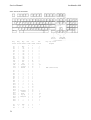
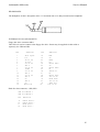
KEY SWITCH MAPPING
Key
Key
Key
Row
Col.
See
Posn Size Name code code table
26
Fl
F2
F3
F4
F5
F6
F7
F8
F9
F10
F11
F12
F13
F14
F15
F16
1
1
1
1
1
1
1
1
1
1
1
1
1
1
1
1
Esc
F1
F2
F3
F4
F5
F6
F7
F8
F9
F10
F11
F12
Print
Scroll
Break
0
0
0
0
0
0
0
0
0
0
0
0
0
0
0
0
0
1
2
3
4
5
6
7
8
9
A
B
C
D
E
F
1
2
2
2
2
2
2
2
2
2
2
2
2
1,3
1
1
E1
E2
E3
E4
E5
E6
E7
E8
E9
E10
Ell
E12
E13
E14
E15
E16
E17
E18
E19
E20
E21
E22
1
1
1
1
1
1
1
1
1
1
1
1
1
1
1
1
1
1
1
1
1
1
1
2
3
4
5
6
7
8
9
0
backspc
Insert
Home
Pg up
Numlock
/
*
#
1
1
1
1
1
1
1
1
1
1
1
1
1
1
1
1
2
2
2
2
2
2
0
1
2
3
4
5
6
7
8
9
A
B
C
D
E
F
0
1
2
3
4
5
1
1
1,3
1
1,4
1
1
1
D1
D2
D3
1.5
1
1
Tab
Q
W
2
2
2
6
7
8
= +
1
Key cap front
Legend
TBA (P959 Pause)
Archimedes 440
Key
Posn
Key
Size
D4
1
D5
1
D6
1
D7
1
D8
1
D9
1
D10
1
D11
D12
1
D13
1
D14 1.5
D15
1
D16
1
D17
1
D18
1
D19
1
D20
1
1
D21
Cl 1.75
C2
1
C3
1
C4
1
C5
1
C6
1
C7
1
C8
1
C9
1
C10
1
C11 1
C12
1
C13 2.25
C14
1
C15
1
C16
1
C17
1
Bl 2.25
B2
B3
1
B4
1
B5
1
B6
1
B7
1
B8
1
B9
1
B10
1
B11 1
B12
1
B13 2.75
B14
1
B15
1
B16
1
B17
1
Service Manual
Key
Name
Row
code
E
R
T
Y
U
I
0
2
2
2
2
2
2
2
3
3
3
3
3
3
3
3
3
3
3
3
3
3
3
3
4
4
4
4
4
4
4
4
4
4
4
4
4
4
4
4
5
5
5
5
5
5
5
5
5
5
5
5
5
1
P
( {
1 )
\ I
Delete
Copy
Pg dwn
7
8
9
Ctrl
A
S
D
F
G
H
J
K
L
, .
, "
return
4
5
6
+
shift
"Spare"
Z
X
C
V
B
N
M
, <
. >
/ ?
shift
crsrUp
1
2
3
Al
1.5 Caps
A2
1.5
Alt
A3
7.0 Space
A4
1.5
Alt
A5
1.5 Ctrl
A6
1
crsrLt
A7
1
crsrDn
A8
1
crsrRt
A9
2.0
0
A10
1
A11 2.0 Enter
5
5
5
6
6
6
6
6
6
6
6
Col.
code
9
A
B
C
D
E
F
0
1
2
3
4
5
6
7
8
9
A
B
C
D
E
F
0
1
2
3
4
5
6
7
8
9
A
B
C
D
E
F
0
1
2
3
4
5
6
7
8
9
A
B
C
D
E
F
0
1
2
3
4
5
6
7
See
Table
1
1
1
Key cap front
Legend
TBA (E1100 End)
1
1,3
1
1
1,3
1,3
1
1,4
1,3
1,3
1,3
1
1
1
TBA (A1009 Action)
1
Row and column codes are in Hexadecimal
Key positions are as shown on page 26.
Key position with N key rollover.
Green light emitting diode under key cap.
27
Service Manual
Archimedes 440
Hard Disc Drive and Interface Circuit Description
All functions of the Hard disc drive are controlled by the Hitachi HD63463 Hard disc Controller chip
(IC22).
HOST CPU CONNECTION
This device is connected to the system CPU by means of the 16 bit I/O bus. It is memory-mapped from
address &032D0000 to &032DO028. The only unusual feature of this circuit is the use of an address line for
the HD63463 read/write line. This is necessary to allow the host CPU to simulate DMA cycles, during
which this line reverses its function.
Reset is provided by the host system, as is the 8 MHz clock (CLK8) from which all host communication
signal timing is derived.
ST506 HARD DISC INTERFACE
The connection to the Hard disc drive is an implementation of the standard ST506 interface. Drive control
signals are provided on a 34-way bus which may be daisy-chained for up to four Hard disc drive units,
and data is transferred on a separate 20-way cable for each drive in the system.
Before any data transfer can take place between the Hard disc drive and the HD63463, the correct drive
and correct read /write head in that drive must be selected. This is achieved by two drive select lines and
three head select lines, all buffered by a 7406 (IC33). Having selected the drive, the HDC (Hard Disc
Controller) will check the READY line before proceeding with the required function. A failure of this
signal (or the SEEK COMPLETE signal, see below) may result in a polling action (ie repeated attempts to
select) by the HDC. All control signals on the 34-way bus from a Hard disc unit will only be active when
the drive is selected.
If a seek is required before selecting the read/write head then the direction signal DIR will be set high or
low to indicate movement in or out and the requisite number of step pulses transmitted on the STEP
control line. The HDC must then wait for the SEEK COMPLETE (SC) signal to be returned from the drive
unit. As previously mentioned, the HDC may go into a polling action while waiting for this signal.
All control signals to the drive are buffered by the 7406 (IC33) and all signals from the drive are buffered
by a 74HCT14 (inverting Schmitt trigger), IC32. Demultiplexing and buffering of the direction (DIR), step
and reduced write current (RE+WC) signals is achieved by a 7438 (IC34).
READ DATA PATH
Read data is received from the drive as a differential signal and applied to the differential receiver 26LS32
(IC39). From here it passes through a multiplexer (this circuit can control two Hard disc drives and onto
the data separator circuit.
DATA SEPARATOR
The data from the Hard disc drive takes the form of a stream of pulses whose position with respect to a
clock signal defines their meaning, binary 1 or 0. The nominal frequency of this clock is 10 MHz although
it may have to vary slightly to compensate for variations in disc speed and/or disk wobble. Since this
clock signal is not provided by the Hard disc drive it has to be generated by the interface circuitry. The
Data-Separator contains a voltage controller oscillator (VCO), some filter components and an input for a
crystal controlled 10 MHz clock. When the HDC is not trying to read data from the Hard disc drive, the
VCO is locked onto the 10 MHz crystal clock.
To read data the HDC first asserts the read-gate signal (RGATE), this causes the data-separator DP8455
(IC50) to attempt to adjust the VCO frequency and phase until the VCO cycles are in quadrature with the
data pulses when they are present.
When the data separator has detected valid preamble (a special pattern of Os and ls) it asserts lock-detect
28
Archimedes 440
Service Manual
(LD) which enables the now synchronised data stream to the HDC. In turn, when the HDC sees a special
data pattern called an address mark it asserts SYNC. This signal is linked back to the data separator and
used to slow down the tracking action of the VCO during the actual read process.
WRITE DATA
Write data timing is synchronised to the 10 MHz crystal oscillator. The data emerges from the bidirectional data pin RWDATA on the HDC and is fed to a delay line (IC42) which is a 50 nS 5-tap device.
This gives three identical versions of the write data stream separated in time by 10 nS. These three signals
are fed to a multiplexer 74HCT153 (IC41) which selects the appropriate version of the write data stream
when manipulated by the write-precompensation control lines EARLY and LATE. Finally, the data is
passed through a differential driver 26LS31(IC40) before going on to the Hard disc drive itself.
FORMAT
Data is stored in the form of sectors. There are 32 sectors on each track and 4 tracks in each cylinder.
A sector has an ID (identity) field and a DATA field. The ID field contains the sector's number and the
DATA field contains the data stored in that sector.
Before data can be written to the data field of a sector, the correct sector must be located by repeated
reading of ID fields on the track until the required sector is found.
29
Service Manual
Archimedes 400 series
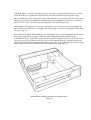
3. Disassembly and Assembly
The main unit houses the main PCB, the PSU, the cooling fan, the Hard disc drive and 3.5" floppy disc
drive. Provision is made for the installation of a variety of Podules via the backplane board.
The keyboard, mouse and monitor are separate units. See the appropriate third-party service information
for the monitor. The mouse is a service replacement only item.
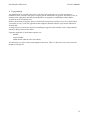
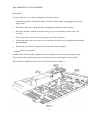
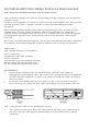
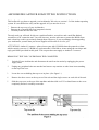
Main Unit
DISASSEMBLY
1.
Disconnect the computer from the mains supply and all peripherals, including the keyboard.
2.
Place the main unit, with the rear panel facing you, on a worksurface with a clean, soft covering.
3.
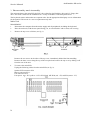
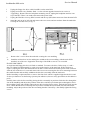
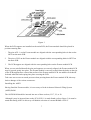
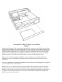
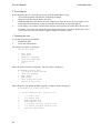
Remove the top cover as follows (see fig. 1):
Remove the two screws in the sides of the top cover, immediately behind the front moulding.
Remove the three screws along the top of the rear panel and remove the top cover by sliding it off
from the rear of the unit.
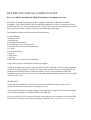
4.
To remove the main PCB:
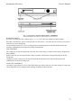
Unplug the following cables from the main PCB (see fig. 2):
Speaker/LED connector PL9.
Battery connector PL 11.
Fan connector PL12.
Four power tags - PL5 (vellow. +12VO. PL6 (black. OW PL& (red. +5V) and PL8 (mauve. -5V).
30
Archimedes 400 series
Service Manual
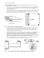
5.
Unplug the floppy disc drive cable from SK11 on the main PCB.
6.
Unplug and remove any Podules fitted - see the relevant upgrade instruction in section 4,
"Upgrading". Remove the two backplane mounting screws, unplug the backplane and rest it on
top of the PSU. There is no need to disconnect the power leads.
7.
Unplug the Hard disc 34-way (SK10) control and 20-way (SK9) data connectors from the main PCB.
8.
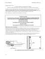
Stand the unit up on its left side and remove the two screws and star washers from the underside
securing the rear bus bars (see fig. 3).
9.
Remove the 3 screws from the underside securing the rear moulding.
10.
Stand the unit back on its feet and begin to withdraw the rear moulding, with the main PCB
attached, out of the case. Support the front edge of the PCB as soon as it is accessible.
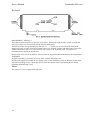
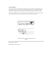
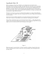
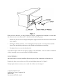
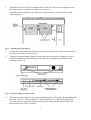
FLOPPY DISC DRIVE
A single internal floppy disc drive is fitted as standard. To remove the drive, follow steps 1, 2 and 3
above in "Main Unit Disassembly" to gain access to the interior of the main unit. With reference to
Figure 4, unplug the drive data ribbon cable from SK11 on the main PCB and the power cable connector
from the rear of the drive. Locate and remove the two screws securing the disc drive mounting bracket to
the saddle bracket and carefully withdraw the disc drive assembly from the main unit.
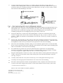
Before installing a replacement drive, remove the front facie which is supplied clipped to the drive and
fix the eject button to its shaft using cyanoacrylate adhesive (observe safety precautions on the adhesive
pack).
Partially insert a disc before carefully placing the drive assembly in position. Guide the disc through the
slot in the moulding and adjust the position of the drive until the eject button passes through its slot in
the moulding. Insert and partially tighten the two drive bracket fixing screws. Push the disc fully into the
drive. Check that the drive will accept and reject discs and that the eject button does not bind on the
moulding. Adjust the position of the drive mounting bracket if necessary -, then finally tighten the fixing
screws.
31
Archimedes 400 series
Service Manual
POWER SUPPLY UNIT
CAUTION: DOUBLE POLE/NEUTRAL FUSING
The PSU is fitted with a double-pole switch and both the Live and Neutral lines are fused.
To remove the PSU, ensure that all low voltage captive leads are disconnected and free from restraints.
Remove the fan then remove the four M3 x 6 mm fixing screws from the underside of the base
metalwork. Slide the PSU forward to clear the rear moulding, then lift it clear. When installing a PSU, the
system should be tested for satisfactory earth continuity in accordance with IEC 950*.
NOTE: THE PSU IS A SERVICE REPLACEMENT ONLY ITEM.
FRONT MOULDING ASSEMBLY
Remove the two screws securing the front moulding assembly at each side. Stand the unit on one side
and remove the three screws securing the front moulding assembly to the base metalwork (see fig. 5).
Stand the unit back on its feet and unplug the LED/speaker connector PL9 from the main board
(see fig. 2). Grasp the front moulding assembly at each end and use a straight, steady pull to withdraw it
from the front of the unit.
For access to the indicator LEDs, locate and remove the two self-tapping screws at each end inside the
main front moulding and slide the sub-moulding away from the main moulding (see fig. 6)
32
Archimedes 400 series
Service Manual
HARD DISC DRIVE
To remove the hard disc drive, follow steps 1, 2, 3, 5, 6 and 7 above in "Main Unit Disassembly".
Disconnect the hard disc power leads from the rear of the drive - note that some drives may have a power
connector on a short flying lead.
Locate and remove the two screws securing the drive mounting bracket from the saddle bracket and
carefully withdraw the drive/bracket assembly from the unit.
FAN ASSEMBLY
The cooling fan is mounted against the front left side of the casing (viewed from the front), alongside the
battery holder.
Remove the four nuts securing the filter clamp; carefully withdraw the clamp and the filter from the
fixing bolts.
Unplug fan power connector PL12 from the main PCB, then remove the four remaining nuts and
withdraw the fan from the fixing bolts.
MAIN UNIT ASSEMBLY
Assembly is generally the reverse of the disassembly procedures, but take care with routing of cables and
ensure that leads are not trapped when refitting assemblies to the main unit.
33
Service Manual
Archimedes 400 series
Keyboard
DISASSEMBLY - SEE FIG. 6
Invert the keyboard and place it on a soft, level surface. Remove the eight Pozidriv screws securing the
two halves of the case and carefully lift the base moulding away.
The PCB is fixed to the top moulding by four No. 6 x 1 /4" screws, two at each end of the metal PCB
support tray plus, on some units, three further screws at A, B and C. Remove the three extra screws first,
if fitted, then remove the two screws from the end nearest to the keyboard cable. Loosen the two
remaining Brews and lift the board clear.
Note that the reset switch cap must be removed from the original keyboard and fitted to the replacement.
ASSEMBLY
Keyboard assembly is generally in reverse order, with the following notes:
Slot the PCB support tray under the two fixing screws at the end furthest from the Keyboard cable, then
insert the remaining screws. Check that all keys clear the cutouts in the top moulding before finally
tightening all PCB fixing screws.
Mouse
The mouse is a service replacement only item.
34
Archimedes 400 series
Service Manual
4. Upgrading
Any modification or upgrade carried out to the printed circuit board of any Acorn equipment is
undertaken at the sole risk of the person carrying out the modification or upgrade. No claim for loss or
damage to the equipment caused by the modification or upgrade by unskilled personnel shall be
accepted by Acorn Computers Ltd.
Before commencing an upgrade, please read all of the instructions carefully. If you are in doubt about
your ability to carry it out, the upgrade kit and computer should be taken to your nearest authorised
Acorn dealer.
A charge may be levied by the dealer for installing the upgrade in the machine, such a charge shall be
entirely at the discretion of the dealer.
Upgrades applicable to model 440 computers are:
Podules
Econet Module
MIDI module (add-on to the I/O Podule)
The following are copies of the actual upgrade instructions. These are the latest issues at the time this
manual was prepared.
35
BACKPLANE INSTALLATION LEAFLET
For use with the Archimedes High Performance Computer System
Any Podule is installed by plugging it into an adapter, inside the Archimedes, called the
` backplane'. This leaflet describes how to install the backplane as well as a cooling fan which is
included with the kit. It is essential that the fan is fitted at the same time as the backplane to ensure
that the machine remains within its specified operating temperature range.
The backplane fitting kit should contain the following parts.
For the backplane:
1 backplane PCB
1 mounting bar
2 hexagonal plastic spacers
4 self-tapping screws to fit the spacers
2 straight screws to locate the mounting bar
1 tie-wrap
For the fan assembly:
1 fan unit
I filter clamp
1 fan filter
4 bolts and 6 nuts to locate the fan and filter
If any of these parts is missing then consult your supplier.
Fitting the backplane necessitates removing the lid of the Archimedes. The only tools required to
do this are a medium Posidriv screwdriver (which is also needed to locate the mounting bar, the
backplane PCB and the fan unit) and a M4 spanner. If you are not confident of fitting the
backplane yourself, then please take your Archimedes and the backplane fitting kit to your dealer
who will fit it for you.
WARNING
Ensure that the Archimedes is switched off at the rear and that the mains supply cable is
disconnected from the mains before removing any covers.
Under normal operation, hazardous voltages exist in the power supply unit. Do not push, dangle
or drop objects through the ventilation holes of the PSU case.
If for any reason, the PSU is removed from the casework, then on reassembly, the system should
be tested for satisfactory safety earth continuity as detailed in the Archimedes Service manual.
1
DISASSEMBLY
First, make sure that the Archimedes is disconnected from the mains by unplugging the power
supply cable, and remove any peripherals (including the keyboard) that are attached. Clear the
Archimedes completely, that is, remove any monitor from on top and any other loose items.
The top case is held by three screws at the top rear of the unit and one screw on each side of the
unit. These must be removed. The position of these screws are shown in figure 1.
The position of the screws holding the top case
Figure 1
Once you have removed the five screws, the lid of the unit will slide back and off. Remove the lid
from the unit completely.
The backplane can now be fitted.
2
FITTING THE BACKPLANE
The first task is to affix the backplane PCB to the backplane mounting bar using the hexagonal
plastic spacers and'the four self-tapping screws..
It is vital to get the PCB and the mounting bar in correct relation to one another, and to use the
correct two holes in the mounting bar. (See figure 2.)
The correct relation of the mounting bar and the backplane PCB
Figure 2
3
Following figure 2, use four self-tapping screws and the two hexagonal plastic spacers to mount
the PCB on the bar. Tighten the screws until the assembly becomes a firm unit with no play.
On the Archimedes, there is a bunch of cables and connectors tie-wrapped to the side of the power
supply unit. Some of these cables are needed to power the backplane, so cut the tie-wrap using a
pair of scissors. Take care not to cut or damage any of the cables themselves.
The backplane mounting bar is located on two flanges. One is located on the power supply unit
near to where the cables were tie-wrapped. The other flange is located on the opposite side of the
unit. (See figure 3.)
Next, take the backplane PCB attached to its mounting bar and, with the mounting bar nearest the
front of the Archimedes, plug the connector on the backplane into the connector on the
Archimedes PCB. As you do this, ensure that the connector is aligned correctly and do not use any
excessive force. If it is difficult to plug in, then it is not aligned correctly, so remove it and start
again. Be careful that the mounting bar does not snag on any of the cables that you have just freed.
All the cables must be loose and in front of the mounting bar. (See figure 3.)
The backplane and fan assembly mounting points
Figure 3
4
When the backplane is located on the Archimedes PCB, the backplane mounting bar should line
up fairly closely with the flanges on the Archimedes. Use the two straight screws supplied and
gently manipulate the Archimedes lower case and the backplane mounting bar until they locate
through the bar and into the holes below. Tighten up the screws in such a position as the backplane
PCB is as near vertical as possible. The holes in the backplane mounting bar are oval for this
purpose.
Take the black single wire from the bunch that was freed and connect it to the tag on the backplane
PCB labelled OV.
Take the red single wire and connect it to the tag on the backplane PCB labelled +5V.
Take the yellow single wire and connect it to the tag on the backplane PCB labelled +12V.
If a hard disc drive is already fitted to the Archimedes then the installation of the backplane is now
complete.
If a hard disc drive is not fitted then the power supply cable used for it is still hanging free. This
cable, which has a large plastic-covered connector on the end, must be tied out of harm's way to
the backplane mounting bar using the new tie-wrap supplied. Make sure that there is no way that
the live pins in the connector can come into contact with any surface in the Archimedes, such as
the power supply unit, or the PCB, or the backplane mounting bar itself.
The backplane unit is now installed.
FITTING THE FAN ASSEMBLY
The fan assembly locates on the left side of the Archimedes, just in front of the power supply unit.
There are four holes in the case arranged in a square pattern. The fan assembly locates on four
bolts through these holes. (See figure 3.)
First, examine the fan unit itself. There are two arrows inscribed on its case, one showing the
direction of rotation, and one showing the direction of airflow. The arrow indicating the direction
of airflow must point into the Archimedes case when the fan is installed.
Take the four bolts and insert them, from the outside, into the four holes. Place one hand over all
four bolt heads to stop them from being pushed out.
Take the fan unit and, ensuring that it is the correct way round as described above, pass its
mounting holes over the four bolts which protrude into the case.
Put a nut on each bolt, and, holding each nut in turn with one hand, use the Posidriv screwdriver to
tighten the bolt from the outside.
5
Next, take the fan filter and pass it over the four bolts, being careful not to tear it. Locate the filter
so that the nuts fit through the cutouts and the filter is flush against the face of the fan.
Take the filter clamp and pass this over the four bolts. Fit the two remaining nuts on to the top
right and bottom left bolts (as viewed from inside the machine). Tighten the nuts, using an M4
spanner. Be careful not to trap the filter material between the filter clamp and the four fan-fixing
nuts.
Finally, plug the power supply connector from the fan lead on to the connector labelled PL12 on
the Archimedes PCB. This connector will only engage correctly one way round.
The fan assembly is now installed.
REASSEMBLY
Once the backplane and fan unit are correctly installed, slide the top case of the Archimedes on
from the rear, making sure that it is correctly located in the two slots, one on each side of the lower
case.
First replace the three screws at the rear of the unit and tighten them up. (See figure 1.)
Finally replace the two screws, one on each side of the case and tighten them up. (See figure 1.)
6
REPLACING THE FAN FILTER
To replace the fan filter, proceed as follows:
-
undo the two M4 nuts retaining the filter clamp
-
remove the clamp and filter
-
replace the filter with a new one
-
refit the clamp and the two M4 nuts
7
"-'Acorn Computers Limited
Published by Acorn Computers Limited
March 1988
Part number 0476,040, Issue 2
8
ECONET MODULE FITTING INSTRUCTIONS
FOR USE WITH MASTER 128, MASTER COMPACT AND ARCHIMEDES
300/400 SERIES
These instructions explain how to install an Econet module into a Master 128, Master Compact
and Archimedes 300/400 series microcomputer. After reading the Introduction you should then
refer to the part of the instructions relevant to your machine.
INTRODUCTION
Any modification or upgrade carried out to the printed circuit board of any Acorn equipment is
undertaken at the sole risk of the person carrying out the modification or upgrade. No claim for
l oss or damage to the equipment caused by the modification or upgrade by unqualified personnel
shall be accepted by Acorn Computers Limited.
Before commencing an upgrade please read all of the instructions carefully. If you do not feel
confident to carry out this upgrade then take the upgrade kit and your computer to an Acorn
Computers' authorised dealer for upgrade installation.
A charge may be levied by the dealer for installing the Econet upgrade in your machine, such a
charge shall be entirely at the discretion of the dealer.
IMPORTANT: Most electronic devices can be damaged by static electricity. To
reduce the possible adverse effects of static electricity note the following points
when installing any component(s) or upgrade:
• avoid personal static charge where possible
• avoid working in areas where there are manmade fibres, eg nylon carpets and
nylon clothing
• after the computer is disconnected from the mains, touch the metalwork of the
case while performing the upgrade to ensure that you and the computer are at an
equal potential
• keep the IC(s) in anti-static foam until fitted
• avoid touching the pins of the IC(s) during fitting
This upgrade may require the installation of a ROM into your computer. It is important to be able
to identify pin one on the ROM so that it can be installed in the correct orientation. Pin one is
i ndicated in one of two ways. Either a small dot or dimple is placed directly above pin one, or a
horseshoe shaped indentation is cut into the pin one end of the IC with pin one always being to the
left of the indentation. In some instances both of these indicators will be present.
1
ARCHIMEDES 300/400 SERIES
Disassembly
To remove the top cover of the Archimedes, proceed as follows:
1
Switch the computer off and disconnect it from the mains supply by unplugging the power
supply cable.
2
Disconnect and remove all peripherals, including the keyboard and the monitor.
3
Place the computer, with the rear panel facing you, on a worksurface with a clean, soft
covering.
4
Locate and remove the three screws along the top of the rear panel.
5
Locate and remove the two screws (one in each side of the top cover) immediately behind the
front moulding.
6
Remove the top cover by sliding it off from the rear of the computer.
Installing the Econet module
Included in the Econet module upgrade kit are two plastic printed circuit board support posts.
These must be fitted to the main printed circuit board before installing the Econet module.
The positions at which these posts are to be fitted are shown in figure 1.
2
When fitting the PCB supports, ensure that the base flange does not interfere with any component
on the PCB. To fit the support, insert one end into the hole in the PCB and press down gently.
When the PCB supports are installed on the main PCB, the Econet module should be placed in
position ensuring that:
1
The pins of PL1 on the Econet module are aligned with the corresponding holes in the socket
SK5 on the main PCB.
2
Tile pins of PL2 on the Econet module are aligned with the corresponding holes in the socket
SK6 on the main PCB.
3
The PCB supports are aligned with the corresponding holes on the Econet module PCB.
When you are satisfied that all the pins and supports are correctly aligned, the Econet module PCB
may be pressed gently into place. The Econet module is correctly seated when the barbs on the tips
of the PCB supports have cleared the surface of the Econet module PCB. An audible click should
be heard when the barbs spring into place securing the PCB.
Take care not to exert too much pressure when pressing home tile Econet module PCB, this may
l ead to damage of the various connectors.
Visually check that all is well and re-assemble the computer unit by refitting the top cover and
inserting the five fixing screws, three in the rear panel and one at each side of the computer.
Network Software
The ANFS ROM supplied with the Econet module upgrade is not required in the Archimedes. An
enhanced version of the ANFS software is incorporated into the Arthur operating system ROM
already installed in the Archimedes 300/400 series.
The Archimedes is now ready to be connected to an Econet network. See your Network Manager
who will assign and set your station number.
If you have a version of the Arthur operating system earlier than 1.2 then contact your supplier for
information on how to obtain an upgrade
MASTER 128 AND MASTER COMPACT MICROCOMPUTERS
Machine orientation
Within this fitting instruction, the points of the compass are used to indicate the way in which
components are oriented. With the machine positioned such that the keyboard is nearest you and
uppermost, the nearest edge is designated to be SOUTH, the rear NORTH and right and left are
designated EAST and WEST respectively.
The Econet module will be installed in the NORTH-EAST corner of the printed circuit board on
both the Master 128 and Compact machines.
3
Upgrading the Master 128
Before attempting to fit the Econet module to your machine first ensure that the unit is
disconnected from the mains power supply. The upper half of the case must be removed from the
unit to allow access to the main printed circuit board. To do this, turn the computer upside down
and place it on a firm, flat surface; locate and remove the four fixing screws that hold the upper
half of the case in place. These screws are located on the underside of the unit, two at the rear and
two at the front of the machine, and are labelled FIX. Note that the two fixing screws fitted to the
rear positions are longer than the front two.
When the screws have been removed, carefully turn the computer over again (whilst holding the
two halves of the case together) and remove the upper half of the case by lifting it directly upwards
from the machine.
Included in the Econet module upgrade kit are two plastic printed circuit board support posts.
These must be fitted to the main printed circuit board before installing the Econet module.
The positions at which these posts are to be fitted are shown in figure 2. When fitting the PCB
supports, ensure that the base flange does not interfere with any component on the PCB. To fit the
support, insert one end into the hole in the PCB and press down gently.
Figure 2
When the support is correctly fitted, it will not be possible to withdraw it from the hole in the
PCB. Care must therefore be taken to ensure the correct positioning of the PCB support before
pressing it home.
4
When the PCB supports are installed on the main PCB, the Econet module should be placed in
position ensuring that:
1
The pins of PL I on the Econet module are aligned with the corresponding holes in socket SK5
on the main PCB. The two WEST most holes of SK5, labelled 'A' and 'B', are not used.
2
The pins of PL2 on the Econet module are aligned with the corresponding holes in socket SK6
on the main PCB.
3
The PCB supports are aligned with the corresponding holes on the Econet module PCB.
When you are satisfied that all the pins and supports are correctly aligned, the Econet module PCB
may be pressed gently into place. The Econet module is correctly seated when the barbs on the tips
of the PCB supports have cleared the surface of the Econet module PCB. An audible click should
be heard when the barbs spring into place securing the PCB.
Take care not to exert too much pressure when pressing home the Econet module PCB, this may
lead to damage of the various connectors.
Installing the ANFS
Having fitted the Econet module, it is necessary to fit the Advanced Network Filing System
(ANFS) ROM.
The ANFS ROM must be inserted into one of three sockets, IC27,37 or 41. It is recommended that
socket IC27 should be used where possible. If it is not possible to use socket IC27 then one of the
other two sockets may be used, but it will be necessary to change the position of a link on the main
PCB (see NOTE 1).
To insert the ANFS ROM, hold the ends of the IC between thumb and forefinger, and line up all
the pins over the destination socket. The pin one end of the IC should face to the WEST. If you are
unsure of which way round the IC should be installed, refer to the other ICs on the main PCB
which all face WEST.
Apply firm pressure to the IC, but do not force it. When the chip is in place it may appear to be
slightly raised. Check that all the pins have entered the socket and that none are bent either
outwards or under the body of the IC.
When the Econet module PCB and the ANFS ROM have been installed, the re-assembly
procedure is the reverse of the dismantling procedure.
Setting the station number
Before attempting to add a machine to an existing Econet, the station number must be set. The
Network Manager should be asked to carry out this operation.
NOTE I:Sockets IC37 and 41 share the same address space as four sideways RAM
pages. The position of links LK18 and LK19 determine whether the address space is
claimed by ROM or sideways RAM.
5
These two links are located close to the WEST side of ICs37 and 41, LK18 is used with IC41 and
LK19 is used with IC37. These links consist of a three pin plug with a connector which may be
push fitted onto two pins of the plug to make a connection. There are two possible positions for
this connector:
EAST - the connector joins the central pin to the right hand pin (enables sideways ROM)
WEST - the connector joins the central pin to tile left hand pin (enables sideways RAM)
The use of one of tile sockets with a ROM will preclude the use of 32K (two 16K pages) of
sideways RAM. If both IC37 and IC41 are used in conjunction with sideways ROMs, all four of
the 16K sideways RAM pages will be unavailable.
If IC27 is already occupied and you need all four pages of sideways RAM, you will need to fit tile
ANFS ROM into an EPROM cartridge which can then be plugged into one of the cartridge
sockets.
Further information about the use of sideways RAM/ROM may be obtained from Part 1 of the
Master 128 Reference Manual.
Upgrading the Master Compact
Unplug all peripherals and remove the power lead from the computer.
Lay the computer face down on a flat surface and undo the four case fixing screws. Gently turn
the computer over allowing the screws to fall free. Put them in a safe place until required again.
Lift the top case including keyboard away from the base of tile computer - (taking care not to
strain the ribbon cable) and lay it in front of the machine.
Installing the Econet Module
Included in the Econet module upgrade kit are two plastic printed circuit board support posts.
These must be fitted to the main printed circuit board before installing the Econet module.
The positions at which these posts are to be fitted are shown in figure 3. When fitting tile PCB
supports, ensure that the base flange does not interfere with any component on the PCB. To fit tile
support, insert one end into the hole in the PCB and press down gently.
When the support is correctly fitted, it will not be possible to withdraw it from tile hole in the
PCB. Care must therefore be taken to ensure the correct positioning of tile PCB support before
pressing it home.
6
Figure 3
When the PCB supports are installed on the main PCB, the Econet module should be placed in
position ensuring that:
1
The pins of PL1 on the Econet module arc aligned with the corresponding holes in the socket
SKT4 on the main PCB.
2
The pins of PL2 on the Econet module are aligned with the corresponding holes in SKT5 on
the main PCB.
3
The PCB supports are aligned with the corresponding holes on the Econet module PCB.
When you are satisfied that all the pins and supports are correctly aligned, the Econet module PCB
may be pressed gently into place. The Econet module is correctly seated when the barbs on the tips
of the PCB supports have cleared the surface of the Econet module PCB. An audible click should
be heard when the barbs spring into place securing the PCB.
Take care not to exert too much pressure when pressing home the Econet module PCB, this may
lead to damage of the various connectors.
Installing the ANFS
Having fitted the Econet module, it is necessary to fit the Advanced Network Filing System
(ANFS) ROM.
The ANFS ROM should be inserted into one of three sockets, IC17, 23, or 29.
Although it may be inserted into socket IC38 if PL11 is made South (refer to figure 3) it must be
noted that fitting ANFS in this way will disable selection of external ROMS via PL13.
7
To insert the ANFS ROM, hold the ends of the IC between thumb and forefinger, and line up all
the pins over the destination socket. The pin one end of the IC should face to the WEST. If you are
unsure of which way round the IC should be installed, refer to the other ICs on the main PCB
which all face WEST.
Apply firm pressure to the IC, but do not force it. When the chip is in place it may appear to be
slightly raised. Check that all the pins have entered the socket and that none are bent either
outwards or under the body of the IC.
When the Econet module PCB and the ANFS ROM have been installed, the re-assembly
procedure is the reverse of the dismantling procedure.
Your Master Compact is now ready to be connected to a network, see your Network Manager who
will assign and set your station number.
©Acorn Computers Limited
Published by Acorn Computers Limited
November 1987
Part Number 0459,200, issue 2
8
PODULE INSTALLATION LEAFLET
For use with the Archimedes High Performance Computer System
To install a Podule in the Archimedes you will require an adapter called a `backplane'. The
backplane is available separately and must be installed before you attempt to install the Podule.
Full instructions for installing the backplane are supplied with it.
In order to fit the Podule you will have to remove the lid of the Archimedes and one of the
blanking plates at the rear of the machine. The only tools you will require for this are a No. 1 and a
No. 2 Posidriv screwdriver. If you do not feel confident about performing this operation, you can
take the computer and the Podule to your dealer.
DISASSEMBLY
First, disconnect the Archimedes from the mains by unplugging the power supply cable. Then,
remove any peripherals that are attached and clear the Archimedes completely, ie remove any
monitor from the top of the Archimedes and any other loose items.
Locate the screws holding the top case in place (see figure 1). First, remove the three screws at the
top rear of the unit. Then remove the single screw on each side of the unit.
Once you have removed the three rear screws and the two side screws, slide the top cover to the
rear of the machine and then slide it off. You should remove the top cover completely.
Check that the backplane is fitted to the Archimedes. The backplane consists of a small printed
circuit board mounted vertically on the main PCB. If the backplane is not fitted, then you will
have to purchase one and install it, according to the instructions which are supplied with the
backplane, before you can continue with the installation of the Podule.
On the Archimedes 300 series, the optional backplane has two Podule slots capable of holding up
to two single width or two double width Podules. On the Archimedes 400 series, the backplane
(fitted as standard) can hold up to four single width or two double width Podules.
If the backplane is fitted, but has no free Podule slot, you will have to remove one of the Podules
in order to install the new one.
The backplane has an upper and lower Podule slot(s). These correspond to the two full-width
blanking plates fitted to the unexpanded machine. Each blanking plate is held in place by screws,
one at each end. Choose one of the Podule slots and remove the corresponding blanking plate by
unscrewing the two screws holding the plate in position.
You can now fit the Podule.
FITTING THE PODULE
Before fitting the Podule, examine it to see whether it is a full-width or a half-width Podule.
A full-width Podule has a plate at the rear which extends the full width of the Archimedes. If the
plate on the rear of your Podule does not extend the full width of the machine then you are
supplied with a blanking plate along with a T-piece and two screws. Use these to make the Podule
up to full width of the machine.
Once you have made the backplate of the Podule up to the correct width, you can install it in the
Archimedes.
Figure 2 shows where the Podule locates on the Archimedes.
Support the backplane firmly with one hand and push the connector on the Podule into one of the
sockets on the backplane. The connector should be securely seated, ie the rear plate of the Podule
should be flush with the rear of the Archimedes case. It is important that you offer the Podule up
to the backplane at right-angles to it and that you align the connectors, otherwise, you may bend
the pins or break or disconnect the backplane itself. It does not require great force to install the
Podule correctly. If the Podule will not seat easily, remove the Podule and start again.
When you have fitted a backplane and Podule to your Archimedes, you should find that the
backplane is vertical, assuming that the Podule is fully inserted and screwed to the rear of the
Archimedes.
For some combinations of machines and Podules, however, the top of the backplane may appear to
`lean' towards the front of the machine.
If this is the case, you must insert the two spacers found in this package. Each spacer should be
inserted between the internal face of the Podule backplate and the metal clips on the rear plastic
moulding of the machine, so that the fixing screws pass through both the backplate and the spacers
(see figure 3). This should result in the external face of the Podule backplate panel being flush
with the rear of the machine plastic.
When you have done this, you may find that you need to `straighten' the backplane, to ensure that
the connectors are correctly mated. To do this, take the following steps:
1
Slacken off the two screws fixing the backplane support metalwork to the base metalwork and
power supply.
2
Holding the Podule stationary, ease the backplane back towards a vertical position until the
faces of the interlocking connectors on the Podule and backplane are touching.
3
Re-tighten the two screws slackened earlier.
If you do not require to fit the two spacers, simply secure the Podule to the rear of the Archimedes
case by inserting a screw at each end of the Podule backplate.
REASSEMBLY
Once the Podule is correctly installed, slide the top case of the Archimedes on from the rear.
Replace the three screws at the rear of the unit and tighten them up. See figure 1.
Finally replace the two screws, one on each side of the case. See figure 1.
©Acorn Computers Ltd
Published by Acorn Computers Ltd
March 1988
Part number 0476201, Issue 2
SECOND FLOPPY DISC DRIVE INSTALLATION LEAFLET
FOR USE WITH ARCHIMEDES PERSONAL WORKSTATIONS
These instructions detail how to install a second floppy disc drive upgrade in an Archimedes
computer system.
In order to fit the upgrade, you will have to remove the lid of the computer unit. The only tools
you will require are a No. 1 Posidriv screwdriver and a small flat-bladed 'electrical'
screwdriver.
Please read through the following instructions carefully before you start. If you do not feel
confident about carrying out this installation, take this upgrade and your Archimedes
computer unit to your supplier who will fit it for you. A charge may be levied by the supplier
for installing the upgrade; such a charge shall be entirely at the discretion of the supplier
concerned.
Please take care whilst fitting this upgrade - the disc drive unit and cable assembly are delicate.
Any damage caused whilst fitting this upgrade is unlikely to be covered by the guarantee.
PARTS LIST
In the upgrade package you should have:
One 3.5" Disc Drive
One dual disc drive cable assembly
One drive bracket
One dual disc drive sub-moulding assembly
Model number labels for the front panel
Six M3 x 6 mm Pan Head Pozidriv screws
DISASSEMBLY
1.
Switch off the computer at the rear and disconnect it from the main supply by
unplugging the power supply cable. Then, remove any peripherals that are attached and
clear the computer completely, ie remove any monitor from the top of the unit and any
other loose items.
2.
Locate the screws holding the top case in place (see Fig. 1 below). Remove the three
screws at the top rear of the unit, then remove the single screw on each side of the unit.
Fig. 1: The position of the screws holding the top case.
3.
Once you have removed the three rear screws and the two side screws, slide the lid of
the unit to the rear of the machine and then slide it off. You should remove the lid
completely.
1
FITTING THE UPGRADE
The second floppy disc drive (drive 1) fits alongside the original drive (drive 0) on the disc
drive support bracket, as follows:
1.
Remove the two screws securing the front moulding assembly at each side. Stand the unit
on one side and remove the three screws securing the front moulding assembly to the
base metalwork (see Fig. 2).
2.
Stand the unit back on its feet and unplug the LED/speaker connector PL9 from the main
board (see Fig. 4). Grasp the front moulding assembly at each end and use a straight,
steady pull to withdraw it from the front of the unit.
3.
Unplug and remove the ribbon-type data cable which connects between connector SKI 1
on the main printed circuit board and the connector on the rear of the original disc
drive 0. Connect the centre connector on the new dual drive cable assembly to drive 0
and the end connector to SK1 1 (see Fig. 3).
4.
The new disc drive comes with a front facia panel attached. This facia is fitted to protect
the unit in transit and is not required when the drive is installed in an Archimedes
system. The facia is held in position by two clips, one on each side of the drive. These
may be levered carefully out of position using a small screwdriver and the facia removed.
Take care not to dislodge the drive eject button while removing the facia.
5.
Before fitting the new drive, it must be configured as drive 1. To do this, set the small
slide switch on the side of the drive to position "1" (see Fig. 3).
2
6.
Assemble the drive to the drive bracket with 4 of the M3 x 6mm. screws supplied, using
the original drive 0 assembly as a guide to orientation.
7.
Assemble the drive bracket to the disc drive support bracket with 2 of the M3 x 6mm
screws supplied.
8.
Connect the centre connector on the disc drive power cable and the end connector on the
disc drive data cable to the new drive.
9.
Taking the front moulding assembly, locate and remove the two self-tapping screws at
each end inside the main moulding and slide the sub-moulding away from the main
moulding (see Fig. 5).
Fig. 5 - Front moulding assembly details
10.
The leads from the speaker in the main moulding and the LED in the sub-moulding share
the same connector. The new dual-drive sub-moulding has an LED already fitted to it.
You will need to remove the existing leads from the connector and replace them with
those from the new LED, as follows:
3
11.
Using a small electrical screwdriver or similar, depress the barbs on the LED wire
contacts in the LED/speaker connector (red and black wires) and withdraw the contacts
from the connector, noting the polarity of the LED wires (see Fig. 6, steps 1 and 2). Place
the old front sub-moulding to one side.
12.
Offer up the new dual drive sub-moulding to the main moulding, passing the LED wires
through the drive 1 aperture. Ensure that the top edge of the sub-moulding fits into the
slot between the rib and the top edge of the main moulding, then secure the submoulding using the two self-tapping screws previously removed.
13.
Insert the LED wire contacts into the LED/speaker connector so that the barbs on the
contacts engage in the slots in the connector housing (see Fig. 6, step 3). Observe correct
polarity - make sure that the red and black wires are the correct way round, as shown in
Fig. 6, step 2.
14.
Insert a disc into both drives, then offer up the front moulding assembly to the main unit,
ensuring that the LED/speaker cables pass over the top of the new drive 1. The discs will
aid alignment of the disc eject buttons in the apertures in the front moulding.
15.
Insert the front moulding assembly fixing screws and fully tighten them. Check that both
drives will accept and reject discs, that the eject buttons do not bind on the moulding and
that an inserted disc clears the front moulding.
16.
Provided that its position has not been disturbed, the original drive 0 should align
correctly; if necessary, loosen the new drive 1 bracket fixing screws and adjust carefully
for correct alignment. Tighten both disc drive 1 bracket fixing screws.
17.
Plug the LED/speaker connector to PL9 on the main board, ensuring that the locking ears
on the connector locate either side of the locking tab on the board-mounted connector
(see Fig. 6, step 4).
18.
Visually check that all is well, then refit the top cover and tighten all fixing screws.
19.
Carefully fix the appropriate model label to the new front sub-moulding.
20.
Reconnect the keyboard, monitor and peripherals to the computer unit. Reconnect the
system to the mains supply and switch on. QUIT the desktop (if necessary), then enter:
*CONFIGURE FLOPPIES 2
Refer to the User Guide for further guidance.
Copyright Acorn Computers Ltd
Published by Acorn Computers Ltd
June 1988
Part number 0476,062, Issue 1
4
MIDI MODULE INSTALLATION LEAFLET
FOR USE WITH ARCHIMEDES HIGH PERFORMANCE COMPUTER SYSTEMS
The MIDI Module is an upgrade to the I/O Podule which must also be installed in your Archimedes for
MIDI to function. The I/O Podule must be fitted into a backplane, which is available separately. Full
i nstructions for fitting the backplane and the I/O Podule are supplied with their respective packages.
In order to fit the MIDI Module you will have to remove the lid of the Archimedes unit. The only tools
you will require are a No.1 Posidriv screwdriver and an M2 spanner.
If the I/O Podule and the MIDI upgrade are to be installed at the same time, the alterations to the I/O
Podule should be made before it is installed in the Archimedes. If the Podule has already been fitted it
will have to be removed.
If you do not feel confident about carrying out the installation, you can take the Archimedes and the
Module to your dealer.
DISASSEMBLY
First, switch off the Archimedes at the rear and disconnect it from the main supply by unplugging the
power supply cable. Then, remove any peripherals that are attached and clear the Archimedes
completely, ie remove any monitor from the top of the Archimedes and any other loose items.
Locate the screws holding the top case in place (see Fig. 1 below). First, remove the three screws at the top
rear of the unit. Then remove the single screw on each side of the unit.
Once you have removed the three rear screws and the two side screws, slide the lid of the unit to the rear
of the machine and then slide it off. You should remove the lid completely.
To remove the I/O Podule, if it is already fitted, undo the screws at either side of the rear plate and case
the Podule out of its connector on the backplane, pulling it gently towards you. Make a note of which
connector it was plugged into. Remove the Podule completely from the computer.
PARTS LIST
In the MIDI package you have:
Four ICs (Integrated Circuits) packed on anti-static foam.
Two five pin DIN sockets mounted on a small circuit board with a flying lead and a plug. These are the
MIDI IN and MIDI OUT sockets.
A tiny connector or 'jumper'.
Four nuts, bolts and washers in a plastic bag.
1
FITTING THE MIDI MODULE
The four integrated circuits are plugged into sockets on the I/O Podule. There are three empty sockets,
for which the correct ICs can be identified by the number of pins. (see Fig. 2). You must take care to put
the ICs in the right way round. Pin one is marked by an indent or a spot at one end of the IC which
should line up with the indent drawn on the printed circuit board (see Fig. 2). Also take care not to bend
the pins; if they are splayed out too wide for the socket, press the whole row of pins on one side VERY
GENTLY against a flat surface until they fit.
Fit the ICs by holding the body of the device.
In order to minimise any possible damage to
the IC from static electricity, do not touch the
pins.
The fourth IC replaces the ROM supplied with the 1/O Podule. This is the central integrated circuit in the
row of three large ICs (see Fig. 2). You must remove this IC and replace it with the IC supplied with the
MIDI Module. Take care not to get them mixed up. You will have one IC left over when you have
finished.
The jumper must be inserted over the two pins next to the word MIDI on the Podule circuit board (see
Fig. 2).
Next, the MIDI IN and MIDI OUT sockets are bolted into place on the rear panel of the Podule. First,
remove the two rubber bungs by pushing them through from the circuit board side. The termination of
t he flying lead goes behind the IN lettering on the rear plate of the Podule (see Figs 2 and 3). Take care to
get these sockets the right way up. Bolt the sockets in position using the Posidriv screwdriver, preventing
t he nuts from turning with your fingers or an M2 spanner.
2
Plug the connector on the other end of the lead into the pins on the right hand side of the circuit board
( when you are looking from the rear, see Fig. 2). This will only go in one way round, don't force it.
REASSEMBLY
You can now fit the I/O podule into the Archimedes according to its fitting instructions.
If you had to remove the Podule from the computer, support the backplane with one hand and push the
connector on the Podule into the socket on the backplane from which you removed it. The connector
should be securely seated, that is the rear plate of the Podule should be flush with the Archimedes case. It
is important that you offer the Podule up to the backplane at right angles to it and that you align the
connectors, otherwise you may bend the pins or break or disconnect the backplane itself. It does not
require great force to install the Podule correctly. If the Podule will not seat easily, remove the Podule
and start again.
When the Podule is positioned correctly, secure the Podule to the back of the Archimedes case by
inserting a screw at each end of the Podule rear panel.
Once the Podule has been replaced, slide the top case of the Archimedes unit on from the rear, making
sure that it is correctly located in its slots. These slots are positioned one on each side of the lower case.
Replace the two screws that you removed from the front sides of the Archimedes case and tighten them
up (see Fig. 1).
Replace the screws at the rear and sides of the unit and tighten them up , (see Fig. 1).
Copyright Acorn Computers Ltd
Published by Acorn Computers Ltd
March 1988
Part number 0476,211, Issue 2
3
ARCHIMEDES ARTHUR ROM FITTING INSTRUCTIONS
This leaflet tells you how to upgrade your Archimedes 300 series to version 1.2 of the Arthur operating
system. It is not difficult to carry out the upgrade. All you need to do is to:
•
•
•
Remove the top cover of your Archimedes
Remove the system ROMs (four integrated circuits)
Carefully insert the four new ones.
The only tools you will need for this are a medium Pozidriv screwdriver and a small flat-bladed
screwdriver or IC extraction tool. You will, however, need to take care to protect the ROMs from
static electricity as this can seriously damage them. However, if you are unhappy about upgrading
your Archimedes yourself then your Acorn supplier will be able to do it for you.
ATTENTION! Arthur 0.2 owners - please insert your old 0.2 ROMs into the protective foam
which carried your new 1.2 ROM set, and return the 0.2 ROMs to Acorn using the envelope and
reply paid label provided in this pack. This request does not apply to Arthur 0.3 owners.
REMOVING THE TOP COVER FROM THE COMPUTER
I
Switch off your Archimedes and disconnect the unit from the mains by unplugging the power
supply cable.
2
Unplug any peripherals that are attached and remove any monitor or other loose items standing
on the top of the case.
3
Locate the screws holding the top cover in place. (See figure 1.)
4
Remove the three screws at the top rear of the unit and the single screws on each side of the unit.
5
Slide the top cover to the rear of the machine and then slide it off. You should remove the cover
completely and set it carefully to one side.
LOCATING THE SOCKETS ON THE BOARD
Position the machine so that you are facing the front. The sockets will then be located halfway along
the right-hand side of the main printed circuit board. They are labelled: IC24, IC25, IC26 and IC27.
(See figure 2.)
Note: If you have any Podules installed you will need to remove them in order to gain access to
the ROM sockets.
REMOVING THE OLD ICs
-
You must remove the existing ICs in sockets IC24, IC25, IC26 and IC27. To do this, take an IC
extraction tool or a flat-bladed screwdriver and gently prise up each end of the IC, a bit at a time.
It is important that you remove the ICs extremely gently otherwise you may bend the pins or damage
the sockets. If you are using a screwdriver, be careful not to catch the ribs of the sockets.
IDENTIFYING THE ICs
The upgrade kit consists of four ROMs. The way in which the ICs are labelled and their appearance
depends on the manufacturer. Before inserting the ICs it is important to clearly identify the type of ICs
you are supplied with.
Using the table below, identify which IC is which by examining the markings on them.
ROM
Markings
1
2
3
4
0277,022
027,023
0277,024
0277,025
or
Markings
MB831000-20P-700
MB831000-20P-701
MB831000-20P-702
MB831000-20P-703
or
Markings
1
2
3
4
*Note: The ROM set numbered 1,2,3 and 4 although labelled Arthur 1.1 is in fact Arthur 1.2.
You may find it easier when you come to install the ICs if you make a note of which IC is ROM 1,
ROM 2 and so on.
The ICs will be one of two types. These either have a distinctive semi-circular notch at one end of the
IC or a long groove down one side.
INSERTING THE ICs
You are now ready to insert the ICs. When you handle the ICs, it is very important that you avoid
touching the pins and that you protect the ICs from static electricity.
1
Remove the ICs from their packaging, holding the IC between finger and thumb.
2
Check that all the pins on the IC are straight. If they appear crooked or splayed, you will need to
realign them. To do this, hold the IC sideways-on and press it gently against a firm flat surface.
3
Repeat for the other row of pins as necessary.
4
Identify socket IC24.
5
Take the IC which you have already identified as ROM 1.
6
The new ICs each have only 28 pins so four of the pin positions in each of the 32 pin sockets will
be unused. Position the end of the IC with the semi-circular notch towards the notched end of the
socket. If you have grooved ICs you should position the IC so that the groove is on the left-hand
side of the IC. In either case, the four free positions should be left at the notched end of the
socket. (See figure 3.)
7
Line up all the pins over socket IC24. Ensure that the notch on the IC points towards the notched
end of the socket (or that the groove is on the left-hand side of the IC). Also, ensure that you
have left four free pin positions at the notched end of the socket.
8
When you are sure that the IC is the correct way round, apply firm pressure to the IC until you
feel it click home, but do not force it. When the IC is in place it may appear to be slightly raised.
9
Check that all the pins have entered the socket and that none are bent out or caught underneath.
10
Insert the remaining ICs. Ensure that the IC which you have identified as ROM 2 is inserted into
socket IC25, ROM 3 into socket IC26 and ROM 4 into socket IC27.
REASSEMBLING THE ARCHIMEDES
Now reassemble the Archimedes:
1
If you have removed any Podules, re-install them in accordance with the supplier's instructions.
2
Slide the top cover of the Archimedes unit on from the rear, making sure that it is correctly
located in its slots. These slots are positioned one on each side of the lower case.
3
Replace the screws at the rear and side of the unit and tighten them up. (See figure 1.)
4
Connect up the monitor and keyboard etc and then plug in the mains supply.
The installation is now complete.
In the Desktop, use the mouse (as described in your new Welcome Guide) to select operation.
Note: To go straight to BASIC (rather than the Desktop) set the configuration to LANGUAGE 4.
©Acorn Computers Ltd, 1988
Published by Acorn Computers Ltd
Part number 0476,350
Issue 2
Service Manual
Archimedes 400 series
5. Connectors, interfaces, links and test points
5.1 Archimedes model 440 options and test points
Link No.
Status*
LK 1
Function
Hi-Res Video Clock
LK 2
NF
Selects ROM size for ICs 24 to 27 in combination with LK6. Tracked in position b
27512 EPROM, see also LK 12 and silk screen table.
LK 3
NF
Not applicable
LK 4
NF
Not applicable
LK 5
NF
Not applicable
LK 6
NF
See LK 2, LK12
LK 7
NF
Can be used to ground RDY signal in floppy disc interface for test purposes.
LK 8
LK 9
By fitting both in position 3 to supply PL 4 with power, the disc
drive may be powered via the ribbon cable.
LK 10
NF
West selects SK2 pin 4 to be HSYNC.
East selects SK 2 pin 4 to be CSYNC (tracked East).
LK 11
NF
West selects SK2 pin 5 to be VSYNC
East selects SK 2 pin 5 to be a mode control AMORE. PCB is not tracked in either
position - feature unused.
LK 12
NF
Selects type of 1 Mbit EPROMs/ROMs.
DEFAULT: Links set 1 to 2 and 3 to 4 for EPROMS up to 0.5 Mbit,
1 Mbit ROMs and 1 Mbit ROM-type EPROMS, eg 27C301.
Links set 1 to 3 and 2 to 4, JEDEC 1 Mbit EPROMS, eg 27C101.
LK 13
Selects Hi-Res Sync. or Low-Res Monochrome
LK 14
Selects Hi-Res Sync. or Low-Res Monochrome
TP 1
Access to real time clock oscillator
TP 2
Indicates system access to disc drive.
*NF = Not Fitted
5.2 Plugs and sockets
36
PL 1
Serial line
PL 2
Auxiliary audio connector. 10 way 2 row 0.1" pitch-NF
For pin out see silk screen on PCB.
Unfiltered left channel output
l.
2.
OV
3.
Filtered left channel output
4.
0V
5.
Auxiliary input (feed to internal amplifier and speaker)
0V
6.
Filtered right channel output
7.
8.
OV
9.
Unfiltered right channel output
0V
10.
Archimedes 400 series
PL 3a
Internal clock selection. 4 way 2 row 0.1" pitch.
For pinout see silk screen on PCB; shunts fitted 1 to 2, 3 to 4.
1.
2.
3.
4.
PL 3b
Service Manual
CKSYS 24 MHz system clock.
Feed to VIDC clock
Sync signal
0V
Internal Video 10 way 2 row 0.1" pitch - NF
5 VEDO
(inverse of red data bit 0)
(inverse of red data bit 1)
6 VED1
7 VED2
(inverse of red data bit 2)
(inverse of red data bit 3)
8 VED3
9 SUP
(supremacy output control for external video mixing)
10 HI (horizontal interlace marker)
11HS (horizontal sync)
12 VS (vertical sync)
PL 4
Floppy disc power connector - NF
Used in conjunction with LK8 and LK9 to power floppy drive via ribbon cable.
PL 5
Power supply connector +12 V
PL 6
Power supply connector
PL 7
Power supply connector +5 V
PL 8
Power supply connector
PL 9
Front panel connector, pins 1 to 4 fitted only
1 Speaker connection
2 0V
3 Power on LED connection
4 0V
0V
-5 V
PL 10
Auxiliary I/O connector - NF
1 0V
2 Aux 2
3 Aux 1
4 C4 Bidirectional IO line
5 NVM alarm signal
PL 11
Battery connection
PL 12
Fan connection
PL 13
Monochrome video
37
Service Manual
Archimedes 400 series
ANALOGUE RGB
The red green and blue signals are analogue outputs each designed to drive a 75 ohm terminated line.
Composite sync is also available on the H/CSYNC output. This pin can be link selected to carry the
Horizontial sync. The VSYNC/MODE output is normally unconnected and may be link selected to carry
Vertical sync so long as VIDC is reprogrammed. To maintain high picture quality each signal lead should
be an individually screened co-axial cable of 75 ohms characteristic impedance.
1
2
3
4
5
6
7
8
9
RED
GREEN
BLUE
CSYNC
n/c
OV
OV
OV
OV
Red, Green and Blue into 75 ohms
0
volts
0.7 volts
Minimum Level
( Black)
Maximum Level (White)
H/Csync or Vsync/Mode into 75 ohms
<0.2
>0.3
volts
volts
Sync LOW
Sync HIGH
H/Csync or Vsync/Mode unterminated
<0.2
>2.4
volts
volts
Sync LOW
Sync HIGH
HI-RES MONO VIDEO
The Hi-Res Monochrome output is made available on two BNC connectors. One carries the Hi-Res data
output, a digital signal of a 96 MHz pixel rate, and the other the composite synchronisation signal. Both
are designed to drive 75 ohm terminated lines. The sync output may be link selected to provide a standard
resolution Monochrome output.
Hi-Res Data
0
Volts
0.7 Volts
SYNC into 75ohm
<0.2
Volts
>2.4
Volts
Black
White
Sync LOW
Sync HIGH
Sockets viewed from mating side
38
Archimedes 400 series
Service Manual
PARALLEL PRINTER
1
STB
2
3
4
5
6
7
8
9
10
DO
Dl
D2
D3
D4
D5
D6
_D7
ACK
13
n/c
14
n/c
15
n/c
16
n/c
17
OV
18
OV
19
OV
20
OV
21 OV
22
OV
23
OV
24
OV
11
BSY
12
25
n/c
OV
Vol
Voh
= 0.5 volts at 24 mA
= 2.4 volts at 24 mA
ACK and
Vol
Voh
BSY
= 0.8 volts
= 2.4 volts
ECONET
This socket provides the standard Econet interface.
1
2
3
4
5
Data
Ov
Clock
Data
Clock
Sockets viewed from mating side
39
Archimedes 400 series
Service Manual
KEYBOARD CONNECTOR
Signal name
5 volts
0 volts
Serial Data out(to K'board)
Serial Data in (from K'board)
Reset
-Not connected-
Pin number
4
3
6
5
1
2
MOUSE CONNECTOR
Pin function
5v supply for Mouse
0v return for mouse
Switch 1
Switch 2
Switch 3
X Reference
X Direction
Y Reference
Y Direction
Pin number
6
4
2
3
8
1
5
7
9
Movement signals are T.T.L. level with a fan out of 1 LS load.
Vol
Voh
= 0.5 volts at Iout of 0.4mA
= 2.4 volts at Iout of -0.1mA
Rise and fall time
20p maximum, Vol to Voh or Voh to Vol.
Each mouse switch operates with a contact closure to 0 V.
The switch debounce period is 20 ms minimum.
SERIAL PORT
1
2
3
4
5
6
7
8
9
DCD
RxD
TxD
DTR
0 Volts
DSR
RTS
CTS
RI
See also the Serial Port Application Note in the Appendix.
Sockets viewed from mating side
40
Archimedes 400 series
Service Manual
HEADPHONES
The headphone socket is designed to drive 1 V maximum into a 32 ohm personal-stereo headphone.
INTERNAL PLUGS AND SOCKETS
Floppy disc drive connector SK11
This socket is used to connect to the floppy disc drive. Power may be supplied via this cable or
separately. See LK8 and LK9.
Pin
Function
1
2
3
4
5
6
7
8
9
10
11
12
13
14
15
16
disc eject
n/c
5V or 0V
in use
5V or 0V
SEL 3
5V or 0V
index
5V or 0V
SEL 0
5V or 0V
SEL 1
0V
SEL 2
0V
Motor On
Pin
18
19
20
21
22
23
24
25
26
27
28
29
30
31
32
33
Function
DIR
0V
STEP
0V
Write Data
0V
Write Gate
0V
Track 00
0V
Write Prot
12V or 0V
Read Data
12V or 0V
Side Sel
12V or 0V
Hard disc data connectors - SK8, SK9
SK8 for DRIVE 1
SK9 for DRIVE 0
Pin
Function
13
14
17
18
Write Data +
Write Data Read Data +
Read Data -
41
Archimedes 400 series
Service Manual
Hard disc control connector SK10
This connector carries Hard disc control signals.
42
Pin
Function
Pin
Function
1
2
3
4
5
6
7
8
9
10
11
12
13
14
15
16
17
0V
RWC or HS3
0V
HSEL2
0V
WG
0V
SC
0V
TRK00
0V
WFLT
0v
HSELO
0V
n/c
0V
18
19
20
21
22
23
24
25
26
27
28
29
30
31
32
0V
34
HSEL1
0V
INDEX
0V
DRDY
0v
STEP
0V
DSELO
0V
DSEL1
0v
n/c
0V
n/c
DIRIN
Service Manual
Archimedes 440
6. Fault-finding information
The purpose of this fault-finding information is to enable the engineer to trace faults to module level and,
unless the module is non- serviceable, to component level. The modules are defined as the:
Main PCB,
PSU*
Floppy disc drivet
Hard disc drivet
Podule(s), as fitted
Podule backplane
Keyboard**
Mouse*
Monitort
*
**
These are available as service-replacement only items and are non-serviceable.
These are part-serviceable but include service-replacement only items.
t
These items are third party units, for which service information is available separately.
It is important to determine as closely as possible the nature and location of the fault in order to identify
the faulty module.
Test equipment required:
100 MHz oscilloscope
DC Voltmeter
Continuity tester
In addition, reference should be made to the Circuit diagram on page 109 and PCB test point and layout
diagrams on pages 101 and 103.
In all instances, follow through the checks until the fault is located and identified, then change or repair
the appropriate module. For information on module replacement procedures, etc., see the Acorn Service
and Support Strategy document.
CAUTION
REPAIRS TO MULTI-LAYER PCBs
The main PCB is a four-layer board. Components should only be removed from the board using
equipment specifically designed for this purpose. For details of suitable equipment available, contact
Acorn Computers Ltd.
43
Archimedes 440
Service Manual
6.1 Basic checks
6.1.1 FIRST, CHECK THE OBVIOUS:
With both the monitor and the computer switched on, check for POWER ON indications (computer and
monitor ON LEDs). If neither have power, check the main fuse in the wall plug.
If the computer is powered but not the monitor, check for power on the AC outlet socket at the rear of the
computer main unit by plugging in a known good monitor. Should this also fail, replace the computer
power supply.
If the monitor is powered but not the computer, an internal power supply fuse may have blown. Replace
the PSU.
If both have power, check by substitution that the monitor and the interconnection cable are serviceable.
Check for the correct power supply output voltages on the main PCB:
PL5 = +12 V; PL6 = 0 V; PL7 = 5 V and PL8 =-5 V
If the power supply is emitting a clicking sound, this indicates either a short between two of its outputs or
a faulty power supply.
Make sure all of the ROMs are inserted correctly and that the relevant links (LK2, LK6 and LK12) are
correct for the type of ROMs used. The options and settings of these links are detailed in section 5,
"Connectors, interfaces, links and test points".
The keyboard CAPS LOCK light should toggle on and off when pressed and assuming a disc is present,
the disc drive light will glow after a *CAT command. If so, this indicates that the system is alive and that
the failure is confined to the video circuitry. See section 6.3.1.
If there is no response, substitute a known good keyboard and repeat the check. If there is still no
response, there is a system failure - change the main PCB. If the substitute keyboard restores normal
working, change the original keyboard PCB.
44
Archimedes 440
Service Manual
6.1.2 FLOWCHARTS
The following flow charts will be useful aids to basic checks:
NO DISPLAY
45
Service Manual
NO SOUND
'TEST PROGRAM:
10 REM > Check all channels
20 VOICES 8
30 FOR channel=l TO 8
90 OSCLI("Channelvoice "+STR$(channel)+" "+STR$(2))
50 NEXT
60 FOR channel = 1 to 8
70 SOUND channel, -15, 100,29
80 PRINTchannel
90 k=GET
100 NEXT
RUN PROGRAM.
PRESS A KEY AND REPEAT 8 TIMES.
PRINTS CHANNEL NUMBER ON SCREEN AND
PLAYS VOICE 2 FOR EACH CHANNEL.
46
Archimedes 440
Archimedes 440
Service Manual
6.2 Run the Archimedes 440 main PCB Functional Test (see Appendix)
Action resulting from test failure
The following notes refer to the test procedures on the PCB functional test disc, and the action that should
be taken as the result of a test failure.
Type/Model:
Memory area fault Perform memory tests, section 6.8, and repair as necessary.
Memory:
Repair as above.
Batterybacked RAM:
Perform "NVM and RTC' tests, section 6.4.6, and repair as necessary.
Loudspeaker.
If no sound, check speaker connections. Substitute a known good speaker and retest. If OK, replace speaker. If test still fails, perform "AUDIO" tests, section 6.4.5,
and repair as necessary.
Headphones:
If no sound or poor/faulty sound on known good headphones, perform AUDIO
tests and repair as necessary. See also Production and Field Changes, Appendix
section 7.2.
Monitor Screen:
If display rolls or is unstable, perform R' reset until correct default value obtained.
If no improvement, perform "Unstable or Scrolling Display" tests, section 6.3.3, and
repair as necessary.
If the display breaks up around its edges and spurious characters appear suspect the
system oscillator. See "Corrupted Display", section 6.3.4.
Colours incorrect or missingWith a full white screen, VIDC IC 17 pins 39,40 and 41 should all have the same
signal on them. If not, change the VIDC IC17.
Floppy Disc:
See "Floppy disc drive", section 6.4.2.
Hard Disc:
Check that the configuration settings are correct. If drive is faulty, replace it with
reference to section 3, "Disassembly and Assembly". For Hard disc interface details,
see section 2, "System Description".
Serial port:
If test fails,see "Serial Port, section 6.4.4". If a fault is reported but the test is passed,
see the Serial Port Application Note in the Appendix for possible explanations.
Printer.
See "Printer", section 6.4.3.
6.3. Main PCB faults
6.3.1 VIDEO FAILURE
Check for +5 V on both ends of Ll, if open circuit then check C14 for short circuit. Also check for 3.5 Volts
(approx.) on 1C 17 pin 43. Should this not be present then check R67.
Check for a 24 MHz clock on 1C 17 pin 19. If missing then check continuity to and through P13a and its
shunt.
Check for video data on 1C 17 pins 39,40 and 41. If not present, check power supply to 1C 17; if present,
before finally changing IC 17.
Check for short circuits on signals VIDRQ and VIDAK.
Check connection of all data lines to VIDC.
6.3.2 SYSTEM FAILURE
In order to eliminate the major devices first, change in turn the ARM 1C 43, MEMC 1C 45, IOC21 and
VIDC IC17. If the system still appears to be dead, proceed as follows:
Check for main system clock of 24 MHz on LK1 position c or d. If absent, check again on IC 15 pins 2 or 3
and change 1C15 if required. Finally, change the crystal XL2.
47
Service Manual
Archimedes 440
Check for clocks on IC45 pin 67 and IC17 pin 19.
Check that the signal RST driving IC 45 pin 44 and IC 43 pin 9 is not stuck high.
Check for the presence and validity of the processor addresses and PHI 1 clock. This can be done by
examining the signals on IC 36 pins 12 to 19, IC 35 pins 12 to 19 and IC 28 pins 16 to 19, whilst holding
down the RESET button on the keyboard. In this situation the processor continuously increments its
address bus. Should any of the signals not toggle, suspect either a short or open circuit on that line.
Should none of the signals toggle, check for the PHI 1 clock on the appropriate IC and at its source on
Q15 emitter and IC 45 pin 66. Also check to see that addresses are being presented to the inputs of the
above devices. Change ICs 36,35 or 28 as appropriate, or if no addresses are present, change the ARM
IC 43.
The data bus can be inspected by probing on resistors R141 to 172. By their nature, it is difficult to
interpret the signals seen, so just check for the ability of the signals to move between logic states. None of
these lines should be stuck premanently high, low or in a midrail state. Any of these resistors may be
removed in order to isolate the DRAM bank from the CPU, thus easing the tracing of shorts, etc. Also
check for short or open circuits on the BDATA bus, IC 11 pins 12 to 19 and IC 19 pins 12 to 19.
Check for shorts on DRAM address bus, either on the DRAMS themselves or on IC 45 pins 28 to 36.
Check for Data and Address signals on all four of the ROMs. This is especially important if the ARTHUR
ROMs have been disturbed, as mis-use of a screwdriver during ROM removal may have damaged or
broken PCB tracks.
Check for all address lines on MC, again with RESET held down.
Check the processor interrupt lines FIQ and IRG pins 8 and 7 on ARM IC 43. Neither of these should be
stuck low. IRQ can be expected to pulse low, FIQ should be high. These interrupts should also be checked
at their source on IOC IC 21 pins 50 and 51. Should these also be low, the interrupt source can be traced
by examining all interrupt inputs to IOC IC 21 on pins 30 to 42 (note that pins 30,31 and 42 are active
high logic).
Check for short or open circuits on the latched IO data bus, IC11 pins 12 to 19 and IC19 pins 12 to 19. This
may well cause a false interrupt condition to occur.
Check corner pins of IOC IC21 for short circuits.
Check for a RAS signal on pin 3 of all the DRAMS.
6.3.3 UNSTABLE OR SCROLLING DISPLAY
The computer may have lost its configuration value for SYNC. Type at the keyboard:
*CON. SYNC 1 (RETURN)
press RESET and see if if any change occurs. Investigate configuration failure as detailed in section 6.4.6.
Check for CSYNC signal on SK2 pin 4. If not present, trace back through LK10, R7 and IC4, finally
changing VIDC IC17.
6.3.4 CORRUPTED DISPLAY
If the display breaks up around its edges and spurious characters appear then investigate the system
oscillator. Replace XL2.
Check DRAM using the test ROMs, - see section 6.8.
6.3.5. COLOURS INCORRECT OR MISSING
With a full white screen, VIDC IC17 pins 39,40 and 41 should all have the same signal on them. If not,
change the VIDC IC17.
Trace each signal through the periphery circuitry and out to SK2 until the fault is found.
Check that IC4 pin 2 is responding to its input on pin 1 (pulls low only).
Make sure that the configuration items "BAUD" and "DATA" are set to sensible values. Check for-5 V
on IC7 pin 8 and R12 to R15. Check for the clock on IC9 pins 6 and 7, change XL1 if faulty. Change ICs 7
and 6.
48
Archimedes 440
Service Manual
6.4 Peripheral area faults
6.4.1 KEYBOARD AND MOUSE
Make sure that the configuration items "DELAY" and "REPEAT" are set to sensible values - see the
Archimedes Welcome Guide.
Check computer interface by swapping to a known good keyboard and mouse. If failure still present,
check continuity of keyboard connector SK 12 and ensure that +5 V can be found on pin 4 and 0 V on
pin 3.
Check functionality of inverting buffers in IC 20, check continuity through R 176 and R 180. Replace IOC
IC 21.
6.4.2 FLOPPY DISC DRIVE
Make sure that the configuration items "STEP" and "FLOPPIES" are correctly set. Check that the disc
drive ID selection switch is in the required position (usually 0). Swap the disc drive for a known good
drive and cable. If this also fails, check the power supply connection for +12 V, +5 V and 0 V (see section
5).
6.4.3 PRINTER
Make sure that the configuration items for "IGNORE" and "PRINT" are set to sensible values. Swap the
printer for a known good printer and cable.
If the printer fails completely, check for a STROBE signal on SK 3 pin 1, trace back through R 33, Q 5 and
R 51 to IC 30. Also check for shorts or open circuits on PACK and PBSY.
If the data printed is incorrect, check the continuity of the data lines into and out of IC 3, though R 25 to R
32 and onto SK 3.
If both the printer and the floppy disc drive fail, change IC 30.
6.4.4 SERIAL PORT
Make sure that the configuration items "BAUD" and "DATA" are set to sensible values. Check for -5 V
on IC 7 pin 8 and R 12 to R 15. Check for the clock on IC 9 pins 6 and 7; change XL 1 if faulty. If OK,
change ICs 6 and 7.
6.4.5 AUDIO
Test the audio with both headphones and internal speaker. Do not forget to issue *SPEAKER ON and
*VOLUME 127 commands.
If only the speaker fails, check connections to the main PCB via PL9 and check IC68 pin 5 for a signal of
3 V amplitude. If no signal is present on pin 5 but can be found on pin 3, change IC68. Check continuity
through R173 and check that IC4 pin 10 is not stuck low.
If there is no audio at all, first check for +5 V on both ends of L3. If this is open circuit, check the condition
of C36 before replacement. Check for-5 V on IC13 pin 11 and R40 and R42. Check for about 3 V on VIDC
IC17 pin 12.
A low amplitude signal should be found on VIDC IC17 pins 13,14,15 and 16. If not, change VIDC. These
signals can be traced through the perpheral circuitry and out to Q9 and Q11. The signal amplitude at
these points should be about 1.5 V pk-to-pk.
Check for short or open circuit on signals "SNDAK" and "SNDRQ" on VIDC IC17 pins 9 and 24.
6.4.6 CONFIGURATION, NON-VOLATILE MEMORY & REAL TIME CLOCK
If the NVM suffers data retention problems and the RTC fails, then, with the computer power off, check
for about 2.8 V on IC16 pin 8. If this voltage is not present, inspect PL11, D3 and the charge state of the
batteries (>1.4 V per cell).
If the NVM IC16 consistently fails on the same data bits, change the device.
If the clock fails to run or runs inaccurately, check and if necessary replace XL3. TP1 allows access to the
clock signal.
49
Service Manual
Archimedes 440
6.5 Podules
Run basic checks first - see section 6.1.
Run the relevant Podule test; if it fails, substitute a known good Podule. If the test still fails, check
through "System failure ", section 6.3.2, tracing all signals through to Podule backplane. If necessary,
replace Podule backplane.
6.6 Keyboard
Make sure that the configuration items 'DELAY' and 'REPEAT' are set to sensible values - eg DELAY 32,
REPEAT 4.
Perform the basic checks first - see section 6.1. Run the keyboard functional test.
If the keyboard is replaced, re-run the keyboard functional test.
6.7 Audio
Run the main PCB Functional test - see section 6.2. for details.
6.8 Test ROMs
The Archimedes series Test ROMs are designed to assist in the repair of all Archimedes systems where
'Failure to Initialise' faults are present - ie the machine appears to be 'dead' on power-up.
The ROMs contain software which can be catagorised in two sections:
1. Main memory test routines.
2. Test routines for use under repetitive reset.
To install the test ROM s, carefully remove the ARTHUR ROM set, ICs 24, 25, 26 and 27 and replace them
with the test ROMs, 0, 1, 2 and 3 respectively - see diagram below. Note the correct position of the ROMs
in their sockets; ROM pin 1 is three rows down from the 'top' of the socket.
Use the bare minimum of hardware to run the system - remove/disconnect all peripherals not needed for
the tests.
50
Archimedes 440
Service Manual
MAIN MEMORY TEST
Providing that the ARM, memory controller and video controller are functioning, the test ROMs will
auto-boot into the menu-driven display below. At any point in the operation of the test ROMs, pressing
the BREAK key or re-powering the machine will re-start the program and re-display the menu.
The memory test checks memory according to memory size selected.
It is possible that faulty memory may lie in the region designated as 'screen memory'. If this occurs, the
video display may become unreadable. For this reason, the sequence 0123456789 is repeated across the
top line of the display. Every 4 digits represents a 32 bit word. Watch for missing or corrupted display.
As the start of the screen memory is known to be at physical address &2000000, it should be possible to
determine the exact device that is faulty by examining the corruption pattern on the display.
The default 'memory size' is &100000 bytes (1 Mbyte), however this may be cycled through 0.5,1, 2 and 4
Mbyte memory sizes by pressing the 'M' key.
When using the ROMs on a machine having memory content other than 1 Mbyte, the video display may
at first appear out of line or incorrect. In this instance press the 'M' key repeatedly until the required
memory size has been selected.
The memory test is cyclic and on completion of each full memory test a full stop ('.') will be displayed.
The 4 Mbyte test takes about 29 seconds.
If for some reason the video display is completely blank or unreadable (eg because of a video fault), a
printed output may be obtained by selecting option 1, the output being produced at the printer port as
well as on the VDU.
If an error is found in the memory, the display will show:
AT ADDRESS &nnnnnnnn WROTE &pppppppp READ xxxxxxxxxxxxxxxxxxxxxxxxxxxxxxxx
where 'nnnn' is the faulty address, 'pppp' is the data written to that address and 'xxxxxxxx' is the data
read back from that address in binary form.
For a model 440, each DRAM IC handles one bit of the 32-bit word; reference to the faulty address's
binary data will identify the bit and the corresponding IC where the fault lies.
The memory tests do not terminate unless an error is found, in which case after reporting 8 or 9 errors,
the test will terminate.
An additional check is now made on the state of CMOS RAM control lines C0 and C1. If either of these
lines are short-circuit to 0 Volts, the Test ROMs will indicate this on power-up.
51
Service Manual
Archimedes 440
REPETITIVE RESET TEST
This section of test code is intended for use when the main memory test menu fails to initialise.
To make use of this section of the ROMs the following test equipment is required:
Oscilloscope
Signal or pulse generator
The purpose of the code is to produce certain signals around specific areas of the PCB. These signals may
then be monitored using the oscilloscope to assess the operation of that area of the circuit.
The code is written in a loop which should execute three times before proceeding to the main memory
test. For this reason the machine must be reset repeatedly.
A suitable square wave or, preferably, a negative-going pulse generator output at 10 kHz should be
connected to the reset line via a component connected to IOC IC21 pin 29.
After setting the border colour to white, the signals should be observable in the following order:
SVPMD low
SVPMD low
SVPMD low
IOC CS & S1
IOC CS & S2
IOC CS & S3
IOC CS & S4
IOC CS & S5
IOC CS & S6
IOC CS & S7
nB/W
low
nB/W
low
nB/W
low
IOC CS & CO
IOC CS & Cl
IOC CS & C2
IOC CS & C3
IOC CS & C4
IOC CS & C5
IOC CS hi
hi
hi
hi
hi
hi
hi
i
hi
hi
hi
hi
hi
hi
Return to start for three executions.
After execution of this code, the border colour is reset to black. The assembler listing for this section of the
code is given below:
Startl
52
LDRT
LDRT
LDRT
r0,
r0,
r0,
[r5]
[r5]
[r5]
LDR
LDR
LDR
LDR
LDR
LDR
LDR
LDR
LDR
r1,
iocmof
r0, [r1,r6]!
r0,
[r1, r6]!
r0,
[ r1, r6]!
r0,
[ r1, r6]!
r0,
[r1, r6]!
r0,
[ r1, r6]!
r0,
[ r1, r6]!
r0, [r1,
r6]!
LDRB
LDRB
LDRB
r0,
r0,
r0,
[ r5]
[ r5]
[r5]
;SVPMD pin low
;
)
) continual toggle of:)
;re-load ioc base addr. -offset
;SVPMD pin high
;IOC CS pin high
;S1 ioc hi
;IOC CS pin high
;S2 ioc hi
;IOC CS pin high
;S3 ioc hi
;IOC CS pin high
;S4 ioc hi
;IOC CS pin high
;S5 ioc hi
;IOC CS pin high
;S6 ioc hi
;IOC CS pin high
;S7 ioc hi
;nB/W pin high
;nB/W pin high
;nB/W pin high
MOV rl #&FE0000 ,
)
)
)
Archimedes 440
Service Manual
STR
MOV
STR
MOV
STR
MOV
STR
MOV
STR
MOV
STR
MOV
STR
r1,
rl
r1,
rl
r1,
rl
r1,
rl
r1,
rl
r1,
rl
r1,
[r7]
#&FD0000
[r7]
#&FB0000
[r7]
#&F70000
[ r7]
#&EF0000
[r7]
#&DF0000
[ r7]
#&FF0000
[ r7]
LDR
STR
r1,
&55555555
rl,[r8]
SUBS
BNE
r9, r9, #1
startl
B
main
set CO
]
]
set C1
I
]
set C2
set C3
set C4
set C5
I
] I.O.C.
]
]
]
]
]
;
reset all
write to printer port
,
53
Service Manual
Archimedes 440
7. Appendices
7.1 Parts Lists .............................................................................................................55
7.2 Production and Field Changes .........................................................................61
7.3 Archimedes Serial Port - Application Note ....................................................63
7.4 Test Instructions .................................................................................................. 65
7.5 Sample Service Report .......................................................................................95
7.6 Function Map ......................................................................................................97
7.7 Plugs and Sockets ...............................................................................................99
7.8 Links and Test Points .......................................................................................101
7.9 Main PCB Component Layout........................................................................103
7.10 Final Assembly Drawing .................................................................................105
7.11 Lower Case Assembly Drawing .....................................................................107
7.12 Main PCB Circuit Diagram .............................................................................109
7.13 440 4-way Backplane Circuit Diagram ..........................................................113
7.14 MIDI Podule Circuit Diagram ........................................................................115
7.15 Econet Module Circuit Diagram ....................................................................117
54
Archimedes 440
Service Manual
7.1 Parts Lists
Items identified by a * are normally available as spare parts. For details of service and spares policy, see
the Acorn Service and Support Strategy document.
Items denoted *t are available in sets only - see 'Component Sets' at the end of the parts lists.
Archimedes 440 Packaging Assembly
Item
4
5
8
9
10
11
12
14
15
16
19
Part No.
0176,003 *
0377,100 *
0277,019 *
0277,029 *t
0277,030 *t
0277,031 *t
0277,033 *
0477,000 *
0477,002 *
0476,003*
0870,353 *
Description
Mouse
Keyboard Assy., Cased
Carton
Packaging, LH
Packaging, RH
Packaging, Keyboard Assy.
Accessories Tray
Welcome Guide
User Guide
BASIC/Sprite Editor Keycard
Power Lead, 2M Long, c/w 13A Plug
Qty
1
1
1
1
1
2
1
1
1
1
1
Remarks
Qty
1
1
1
1
1
2
2
5
5
5
Remarks
Archimedes 440 Final Assembly
Item
4
5
6
7
8
11
13
14
15
16
Part No.
0276,002 *t
0276,003 *t
0276,006 *t
0277,315 *t
0276,017 *t
0817,005 *
0882,655
0882,121
0882,654
0882,949 *
Description
Front Moulding
Front Sub-Moulding
Top Metalwork
Front Label, 440
Base Label
Bat. Alkaline 1 V5 2AH 'AA'
Screw No. 6 x 1/2" Pan Hd. Pozi AB
Screw M3 x 6 Pan Hd Pozi
Screw No. 6 x 3/8" Pan Hd Pozi AB
Spire Clip No. 6
Item 4 to 2
Item 6 to 2
Item 4 to 2/5
For item 4
Archimedes 440 Case Lower Assembly
Item
3
4
5
6
9
10
11
12
15
16
17
18
19
20
Part No.
0176,002 *
0176,004 *
0176,005 *
0176,009 *
0800,460 *
0177,001 *
0177,002 *
0177,003 *
0377,040 *
0276,004 *t
0999,462 *t
0276,010 *
0276,011 *
0276,012 *
0276,013 *t
Description
55W 240V PSU
3.5"1 MB Floppy Disc Drive
Single Drive Cable Assy
Battery Holder Assy
SKT 2W HSNG 0.1" V1
Hard Disc Drive
Hard Disc Cable Assy. 34 way
Hard Disc Cable Assy. 20 Way
4-way Backplane Assy
Rear Moulding
Base Metal (1 piece)
L.H. Busbar
R.H. Busbar
Blanking Panel
Drive Saddle
Qty Remarks
1
1
1
1
1 for above
1
1
1
1
1
1
1
1
2
1
55
Service Manual
Archimedes 440
Archimedes 440 Case Lower Assembly - conrd.
Item Part No.
21 0276,014*
22 0276,026
23 0276,033*
24 0276,034*
25 0276,037*
28 0277,014*
30 0800,606*
37 0884,065*
0884,063*
46 0887,012
48 0890,009*
Description
Drive Bracket, Floppy Disc
Backplane Support Bar
Fan Filter Clamp
Fan Filter
PCB Side Slide Guide
Drive Bracket, Hard Disc
Connector, BNC Socket 75R
Spacer, Nylon 8mm PCB
PCB Support Pillar
Spacer, Plastic Hex. 19.05mmL
Foot Pop-Fit 4mm High
Qty
1
1
1
1
2
1
1
1
3
4
Remarks
Alt. fitted to some models
for items 12 & 22
Archimedes Series Fan Assembly
Item Part No.
1
0800,250*
2 0800,515*
4
0885,212*
Description
Connector Housing 2 Way
Crimp Terminal
Fan
Qty
1
2
1
Remarks
Power
for Item 1
Qty
1
1
4
1
1
Remarks
Qty
1
1
1
1
1
1
1
1
1
4
1
Remarks
Archimedes 440 Speaker & LED Assembly
Item
1
2
4
5
6
Part No.
0799,013*
0799,014*
0800,080*
0800,468'
0835,003*
Description
LED, Green
LED, Amber
Connector Crimp Terminal 4809C
Socket Housing, 6Way
Speaker, 8ohm 0.2W 50mm Dia.
For Item 5
Archimedes 440 Keyboard Assembly
Item
1
2
3
4
5
6
7
8
9
10
11
Part No.
0276,101 *t
0276,102 *t
0276,106 *
0276,107 *
0176,100 *
0276,103*
0276,104 *
0276,105 *
0276,108 *
0890,011 *
0999,438*
Description
Keyboard Case Upper
Keyboard Case Lower
Name Case Label
Logo Case Label
Keyboard PCB Assy.
Leg Moulding
Window Moulding
Friction Pad
Reset Switch Cap Moulding
Rubber Foot
Curly Cable
For item 7
Archimedes 440 Main PCB Assembly
Item
5
6
7
8
9
56
Part No.
0276,032 *
0277,022 *
0277,023 *
0277,024 *
0277,025 *
Description
Programmed PAL 16L8A
1 M Arthur ROM 1 V1.2
1 M Arthur ROM 2 V 1.2
1 M Arthur ROM 3 V 1.2
1 M Arthur ROM 4 V 1.2
Qty
1
1
1
1
1
Remarks
IC44
IC24
IC25
IC26
IC27
Service Manual
Archimedes 440
Archimedes 440 Main PCB Assembly - cont'd
Qty
1
1
Remarks
IC43
IC45
IC17
IC21
Item
11
12
13
14
Part No.
2201,365 *
2201,366 *
2201,367 *
2201,368 *
Description
IC ARM 2um PLSTC
IC MEMC PLSTC
IC VIDC 1A PLSTC
IC IOC PLSTC
17
18
19
20
0502,100
0502,101
0502,102
0502,103
RES 10R
RES 100R
RES 1K
RES 10K
C/MF 5%
C/MF 5%
C/MF 5%
C/MF 5%
22
23
25
27
29
30
31
32
33
34
36
37
39
41
42
44
45
46
0502,104
0502,122
0502,151
0502,181
0502,220
0502,221
0502,222
0502,223
0502,271
0502,272
0502,330
0502,331
0502,333
0502,390
0502,391
0502,470
0502,471
0502,472
RES 100K
RES 1K2
RES 150R
RES 180R
RES 22R
RES 220R
RES 2K2
RES 22K
RES 270R
RES 2K7
RES 33R
RES 330R
RES 33K
RES 39R
RES 390R
RES 470R
RES 470R
RES 4K7
C/MF 5% 0W25
C/MF 5% 0W25
C.MF 5% 0W25
C/MF 5% 0W25
C/MF 5% 0W25
C/MF 5% 0W25
C/MF 5% 0W25
C/MF 5% 0W25
C/MF 5% 0W25
C/MF 5% 0W25
C/MF 5% 0W25
C/MF 5% 0W25
C/MF 5% 0W25
C/MF 5% 0W25
C/MF 5% 0W25
C/MF 5% 0W25
C/MF 5% 0W25
C/MF 5% 0W25
51
53
0502,560
0502,680
RES 56R
RES 68R
C/MF 5% 0W26
C/MF 5% 0W25
63
64
66
0502,681
0502,820
0502,821
RES 680R
RES 82R
RES 820R
C/MF 5% 0W25
C/MF 5% OW25
C/MF 5% OW25
R175
R127,128,176,177,191
R51, 65, 66,196
R2,12,13,14,15,16,17, 61, 67,
178,179
2 R88,102
5 R89,114,120,122,138
3 R134,189,190
2 R35,130
9 R25-33
7 R1, 3, 9,18, 73,101,180
1 R46
1
R125
1
R62
1 R49
4 R181,182,184,185
7 R60,121,123,129,192,193,194
7 R53, 54, 56, 57, 58,107
1 R188
1 R195
1 R62
1 R52
24 R19, 21, 22, 23, 24,34, 36, 38, 90,
91, 92, 93, 94, 95, %,108,109,111,
112,113,126,136,137,173
2 R186,187
59 R4, 5, 6, 7, 8, 64, 69, 70, 71, 72, 74,
75, 76, 77, 78, 87, 97, 98, 99,100,
115,116,117,118,119,141,142,
143,144,145,146,147,148,149,
150,151,152,153,154,155,156,
157,158,159,160,161,162,163,
164,165,166,167,168,169,170,
171,172,183
2 R43,44
1
R45
3 R131,132,174
69
70
71
72
0506,161
0506,250
0506,300
0506,517
RES 43R2
RES 332R
RES 1K00
RES 150K
MF
MF
MF
MF
3
3
5
8
1
1
1%
1%
1%
1%
0W25
0W25
0W25
0W25
0W25 E96
0W25 E96
0W25 E96
0W25 E96
1
5
4
11
R20,41, 59
R37, 50, 63
R103,104,105,106,139
R79, 80, 81, 82, 83, 84, 85, 86
57
Service Manual
Archimedes 440
Archimedes 440 Main PCB Assembly - cont'd
Item
74
76
78
80
81
82
83
85
86
87
88
90
91
92
93
95
96
98
100
102
103
104
105
106
107
109
110
111
Part No.
0508,101
0572,221
0581,113
0590,102
0610,005
0610,010
0611,101
0629,010
0630,100
0630,220
0630,270
0631,012
0631,033
0631,047
0631,056
0631,100
0631,330
0635,221
0640,473
0650,102
0651,105
0650,106
0650,223
0650,333
0650,683
0680,002
0680,100
0685,330
Description
RES 100R
MF 10% 0W50
RES NET 220/330R TF 2%
RES PSET 10K CR 20% HMT
RES NET IK0 TF
10% 9P
CPCTR TANT 4u7
10V 20%
CPCTR TANT 10u
10V 20%
CPCTR TANT 100u 16V 20%
CPCTR CPLT lOn
30V 80%
CPCTR CPLT In
30V 10%
CPCTR CPLT 2n2
30V 10%
CPCTR CPLT 2n7
30V 10%
CPCTR CPLT 12p
30V 2%
CPCTR CPLT 33p
30V 2%
CPCTR CPLT 47p
30V 2%
CPCTR CPLT 56p
30V 2%
CPCTR CPLT 100p 30V 2%
CPCTR CPLT 330p 30V 2%
CPCTR ALEC 220u 16V RAD
CPCTR CER 47n
30V 80%
CPCTR MPSTR ln0 63V 10%
CPCTR MPSTR 1u0 50V 10%
CPCTR MPSTR 100n 50V 10%
CPCTR MPSTR 22n 50V 10%
CPCTR MPSTR 33n 50V 20%
CPCTR MPSTR 68n 50V 10%
CPCTR DCPLR 33/47n
0.2"
CPCTR DCPLR 33/47n AX 12V
CPCTR CER 33p
25V 20%
121
123
125
127
128
130
132
134
136
137
138
140
0701,772 *
0704,110 *
0706,552 *
0708,455 *
0708,583 *
0709,463 *
0710,158 *
0721,198 *
0732,630 *
0732,631 *
0732,632 *
0740,006
0740,016 *
0740,038 *
0742,005 *
0742,374 *
0747,000 *
0747,004 *
IC 1772 FDC 28/0.6"
IC 511000 DRAM 120nS 1M x 1
IC 65C51
IC 8455 Data Sync 20/0.3"
IC PCF8583
IC 63463 HDC 48/0.6"
IC 10158 ECL 16/0.3"
IC 21198 Actv Dly 14/0.3"
IC 26LS30 RS422/423 Drvr
IC 26LS31 RS422/423 Drvr
IC 26LS32
IC 7406 TTL 14/0.3"
IC 7416 TTL 14/0.3"
IC 7438 TTL 14/0.3"
IC 74LS05 TTL 14/0.3"
IC 74LS374 TTL 20/0.3"
IC 74HC00 CMOS 14/0.3"
IC 74HC04 CMOS 14/0.3"
143
145
146
148
149
58
Qty
2
1
1
1
19
6
3
1
3
8
2
1
2
5
1
5
4
1
1
1
1
1
2
2
1
18
53
1
Remarks
R40,42
RP2
HMT
RP1
C40, 'B' x 18
C14, 20, 35, 36, 52, 53
C37, 38, 39
C51
C1, 2, 33
C5, 6, 7, 8, 9,10,11,12
C17,24
C21
C19
C15,16,18, 45, 47
C26
C3, 4, 13, 25, 27
C28, 29, 31, 32
C50
C49
C48
C44
C41
C22,23
C42,43
C46
'Z'
'A'
C34
1
32
1
1
1
1
1
1
1
1
2
2
IC47
IC 51-58, 60-67, 78-85
IC9
IC50
IC16
IC22
IC2
IC42
IC7
IC40
IC6, 39
IC33,38
OPTION
IC34
IC4
IC3
IC46
IC23
1
1
1
1
1
Archimedes 440
Service Manual
Archimedes 440 Main PCB Assembly - cont'd
Item
150
151
152
153
154
155
157
161
162
163
164
166
167
168
169
170
Part No.
0747,014 *
0747,051*
0747,075 *
0747,138 *
0747,573 *
0747,574 *
0748,194 *
0749,014 *
0749,125 *
0749,153 *
0749,573 *
0750,004 *
0750,074 *
0751,574 *
0770,324 *
0770,386 *
Description
IC 74HC14 CMOS 14/0.3"
IC 74HC51 CMOS 14/0.3"
IC 74HC75 CMOS
IC 74HC138 CMOS 16/0.3"
IC 74HC573 CMOS 20/0.3"
IC 74HC574 CMOS
IC 74F194 TTL 16/0.3"
IC 74HCT14 CMOS 14/0.3"
IC 74HCT125 CMOS 14/0.3"
IC 74HCT153 CMOS 16/0.3"
IC 74HCT573 CMOS 20/0.3"
IC 74AC04 CMOS 14/0.3"
IC 74AC74 CMOS 14/0.3"
IC74ACT574 CMOS 20/0.3"
IC LM423 QUAD OP AMP
IC LM386 AUDIO AMP
172
173
174
0780,239 *
0780,510 *
0783,906 *
TRANS BC239 NPN
TRANS ZTX510 PNP T092
TRANS 2N3906 PNP
4
2
10
Q2, 5, 9,11
Q14,15
Ql, 3, 4, 6, 7, 8,10,12,13,16
176
177
0794,001 *
0794,148 *
DIODE SI 1N4001 50V 1A
DIODE SI 1N4148
2
5
D2,3
Dl, 4, 5, 6, 7
182
183
184
185
186
0800,004 *
0800,050 *
0800,051 *
0800,052 *
0800,070 *
CONR 5W SKT DIN RA PCB
CONR 2W WAFR 0.1" ST PCB
CONR 3W WAFR 0.1" ST PCB
CONR 5W WAFR 0.1" ST PCB
CONR 2W SHUNT 0.1"
1
6
2
2
7
SK4 (ECONET)
PL3A, LK12,13,14
LKI
PL2
PL3A, LK1, LK12, PL2
188
189
190
191
192
0800,120 *
0800,131 *
0800,148 *
0800,169 *
0800,185 *
SKT IC 20/0.3" NORM
SKT IC 32/0.6" NORM
SKT IC 48/0.6" NORM
SKT IC 68P PLCC
SKT IC 84P PLCC
1
4
1
3
1
IC44
IC24, 25, 26, 27
IC22
IC17, 21, 45
IC43
194
0800,203 *
FSTN TAB 6.3MM X 0.8 ST PCB
4
PL5, 6, 7, 8 (POWER)
201
202
203
204
205
207
208
209
211
0800,408 *
0800,458 *
0800,469 *
0800,481 *
0800,484 *
0800,642 *
0800,853 *
0800,919 *
0803,100 *
CONR 96W SKT ST ABC PCB
CONR 2W WAFR 0.1" ST LK
CONR 6W WAFR 0.1" ST LK
CONR 5W HSNG 0.1" PCB
CONR 17W SKT HSNG 0.1" PCB
CONR 3W 3,5MM RA PCB JSKT
CONR 2W WAFR 0.156" ST LK
SKT 6W MINDIN RA PCB RFI
CONR 20W BOX IDC LP ST
1
1
1
1
1
1
1
1
2
SK7 (EXPANSION)]
PL11 (BATTERY)
PL9 (FRONT PANEL)
SK6 (NET MODULE)
SK5 (NET MODULE)
SKI (AUDIO)
PL12 (FAN)
SK12 (KEYBOARD)
SK8, 9 (HARD DISC)
Qty
1
1
1
1
5
1
1
1
1
1
2
1
1
1
1
1
Remarks
IC20
IC48
IC77
IC31
IC11,19, 28, 35, 36
IC30
IC5
IC32
IC37
IC41
IC10,18
IC15
IC14
IC29
IC13
IC68
59
Service Manual
Archimedes 440
Archimedes 440 Main PCB Assembly - cont'd
Item Part No.
212 0803,102*
214 0820,019 *
215 0820,100 *
216 0820,480 *
217 0821,327 *
Description
CONR 34W BOX IDC LP ST
XTAL 1.8432MHz HC18/U
XTAL 10.00MHZ HC18
XTAL 48.00 MHz HC18
XTAL 32.768 kHz CC 0.05"
Qty
2
1
1
1
1
219
220
221
0860,005 *
0860,011 *
0860,012 *
COIL RF 33uH AX Q=45
CHOKE RF u33H AX ¢-30
CHOKE RF 2u2H AX Q=30
2
1
1
230
0800,291
0800,271 *
0800,292
0800,272 *
0800,293
0800,273 *
0884,044
CONRD 9W PLG RA PCBLK+LK
CONRD 9W PLC RA PCB+RFI+L
CONRD 9W SKT RA PCBLK+LK
CONRD 9W SKT RA PCB+RFI+L
CONRD 25W SKT RA PCBLK+LK
CONRD 25W SKT RA PCB+RFIL
Rivet, Pop, 3,21)
1 PL1 (SERIAL)
OPTION
1
SK2 (VIDEO)
OPTION
1
SK3 (PRINTER)
OPTION
2 For OPTION items 230, 232, 238
232
238
Remarks
SK10,11 (HD & FLPY)
XLl
XL4
XL2
XL3
Ll, 3
L2
L4
COMPONENT SETS
The following items are available as sets only:
440 MAIN UNIT
Case Metalwork, comprising:
0276,006
0999,462
0276,013
0176,009
Case Metalwork, Upper
Case Metalwork, Lower
Drive Saddle
Battery Holder Assy.
Case Moulding Set, comprising:
0276,002
0276,003
0276,004
Front Moulding
Front Sub-moulding
Rear Moulding
440 Label Set, comprising:
0277,315
0276,017
440 Case Front Label
Case Base Label
Packaging Set, comprising:
0277,029
LH Side Cheek
0277,030
RH Side Cheek
60
440 KEYBOARD
Keyboard Case, comprising:
0276,101
0276,102
Keyboard Case, Upper
Keyboard Case, Lower
Keyboard Label Set, comprising:
0276,106
0277,107
Name Case Label
Logo Case Label
Keyboard Packaging Set, comprising:
0277,031
Keyboard End Cheeks (2 off)
Archimedes 440
Service Manual
7.2 Production and Field Changes
The following information gives changes and deviations made to the Archimedes model 440 during production and is the latest available when this manual was compiled. It will be updated accordingly as
information becomes available.
Main PCB
VIDEO NOISE (ACORN FCO E011 REFERS)
Breakthrough of system noise occurs onto the screen. This shows as rippling on screen and is particularly
noticeable with colour monitors. This seems to be particularly prevalent when running 'Arcwriter'.
If this occurs, solder a IN4148 diode in parallel with R67 (adjacent to VIDC IC17) with the cathode (dark
stripe) at the end nearest Q13. Remove the decoupling capacitor 'A' nearest to IC17, between it and Q12
either by using desoldering equipment or by cutting the capacitor out, leaving wires long enough to
attach a new component. Replace this capacitor with a 22uF 6.3 V or higher axial lead electrolytic
capacitor, eg Farnell part number 030 34229. Observe polarity - positive end furthest away from Q12.
LINK 12
Link 12 enables selection of ROM device types. The default setting is for EPROMs up to 05Mbit,1Mbit
ROMs and 1Mbit non-JEDEC EPROMs. Changing link 12 would allow the use of 1Mbit JEDEC EPROMs.
A link consisting of either four pads or pins and shunts is fitted. If the shunts are reversed, this may stop
the machine functioning. Tracks need to be cut to change the link.
IMPROVEMENTS TO HARD DISC CIRCUITRY (Acorn FCO 2000 refers)
Model 400 has been modified in production to improve the performance of the Hard disc controller
circuitry.
Some early examples, serial numbered 1000001 to 1000122 may suffer intermittent phase-locked loop
failure in the Hard disc controller circuitry, resulting in excessive re-reads.
Units displaying this fault, and which have not already been modified, should be modified as follows:
1. See Fig. 1
Cut the two tracks shown (one on the component side, one on the solder side) to isolate IC37 pin 12.
Add an insulated wire link between vias 'A' and 'B' on the solder side.
Fit an 8K2 resistor, Acorn part number 0502,822, between via B' and IC37 pin 12 (using via 'C').
Fit a 1n2 capacitor (Acorn part number 0630,120) between IC37 pins 10 and 12.
Fit a 1N4148 diode in parallel with the 8K2 resistor - refer to the circuit diagram Fig. 2 for orientation.
61
Service Manual
Archimedes 440
2. See Fig. 3
Remove R125 (and any associated 'piggy back' capacitor) from the PCB.
Fit a 47pF capacitor (Acorn part number 0632,047) into position R125.
Fit a 22K resistor (Acorn part number 0502,223) between the +5 V 'Faston' tab (PL7) and the SOUTH end
of the capacitor now in position R125.
Battery Holder
The battery holder is riveted to the base metalwork. If the battery holder is replaced, care must be taken
to ensure that the fixing rivets are fitted to the two holes originally used. Only two of the four possible
holes hold the battery holder assembly rigid.
PSU
Power Supply Units manufactured by Sanken have a screw head in the case which may foul the rear
panel busbar. If fitting a Sanken PSU as a replacement, it may be necesssary to modify the busbar by
filing a piece out of it to clear the screwhead.
62
Archimedes 440
Service Manual
7.3 Archimedes Serial Port - Application Note
The Serial Port electrical interface is based on the American EIA (Electronic Industries Association)
standard RS423. The interface functionality is based on the RS232 standard.
The RS232 standard defines the interface between Data Terminal Equipment (DTE) and Data
Communication Equipment (DCE) employing serial binary data. In the case of an Archimedes system
using a modem, the computer is the DTE and the modem connected to the Serial Port is the DCE. When a
serial printer is used, or another computer is connected to Archimedes, both devices may appear as DTEs
and the interconnections will be different.
The RS423 standard defines the electrical characteristics of an unbalanced digital interface circuit such as
the Archimedes Serial Port.
The RS232 standard is very broad-based in its scope, and defines the use of a 25-way connector with
many connections between the DTE and DCE. In practice, many equipment manufacturers have found
the only a small sub-set of these connections is necessary and connectors with far fewer pins have been
used. Unfortunately, the selection of the sub-set is often arbitrary and there may confusion over how to
make the best use of the connections provided. Only two wires (plus ground) are actually needed,
theoretically, to make a two-way serial data connection between the DTE and the DCE. The additional
connections are primarily used to carry out "hardware handshaking". The "handshaking" enables the
two pieces of equipment to exert some direct control over each other to allow synchronisation of data
flow. This synchronisation is necessary to avoid data loss. Increasingly, "software handshaking" is used
instead of "hardware handshaking". In this case, whilst data is transmitted along one data line, the other
line is used to carry control information that allows the sender and the receiver to synchronise via
software control at each end.
The Archimedes Serial Port uses a 9-way connector (P-type plug) that is similar in function, but is not
identical, to the 9-way port on the IBM PC/AT or derivatives. The same connecting lead can normally be
used as that supplied for the PC/AT.
The pin connections for the 9-way connector are as follows:
Pin
1
2
3
4
5
6
7
8
9
Function
DXD
RXD
TXD
DTR
GND
DSR
RTS
CTS
RI
Voltage & Logic State
Data Carry Detect
Receive Data
Transmit Data
Data Terminal Ready
Ground Return (0V)
Data Set Ready
Request To Send
Clear To Send
Ringing Indicator
+ve - On (Detected)
+ve - Logic "0"
+ve - Logic " 1"
+ve - On (Ready)
+ve - On (Ready)
+ve - On (Send)
+ve - On (Clear)
+ve - On (Ringing)
The Archimedes Serial Port applications include:
Connection to another computer
In this case, both devices behave as DTEs and the RXD and TXD lines need to be transposed between the
computers. Software handshaking will often be used, with some hardware control "loop-back" locally:
Connect pins 1, 4 & 6 (DCD, DTR and DSR) together
Connect pin 2 (RXD) of the DTE (Archimedes) to TXD of the DCE (modem)
Connect pin 3 (TXD) of the DTE (Archimedes) to RXD of the DCE (modem)
Connect pin 5 (0V) of the DTE to 0V of the DCE
Connect pin 7 (CTS) of computer A to pin 8 (RTS) of computer B
Connect pin 8 (RTS) of computer A to pin 7 (CTS) of computer B
Connection to a modem
In this case, the computer is the DTE and the modem is the DCE. The RXD and TXD lines are not
transposed and the DCD, DTR & DSR lines may be brought into use. The TXD, RXD, CTS, DCD, DTR,
DSR and 0V lines of one device are connected to the same pins on the other device.
63
Service Manual
Archimedes 440
Note: In both of the above arrangements, the CTS line does not behave in quite the same way as for the
existing Master Series or BBC Model B computers. The CTS line on the Archimedes, when disabled, will
cause an immediate cessation of data flow. For byte-oriented protocols, this may be undesirable as the
last character may be corrupted. For applications where this is likely to be a problem, the DSR input
should be used instead of CTS (ie the functions should be reversed). The DSR input, when disabled,
allows completion of the current character.
Connection to a serial printer
Both devices will typically be DTEs and some hardware handshaking may be needed. Connections will
be similar to the "computer to computer" method, but will vary between printer types. The printer
manual should be consulted for guidance.
Baud Rate
The serial controller chip within Archimedes provides one internal timer for baud rate control. If the
Receive and Transmit rates are programmed to be the same, then this timer is used for both. If different
baud rates are needed for Transmit and Receive, then the internal timer is allocated to a system timer.
This system timer is not an exact multiple or sub-multiple of the internal timer. The use of different
Receive and Transmit rates is therefore only recommended for lower speed usage, eg 1200/75 Viewdata.
If only Receive is being used, it is important to program Transmit to the same rate, even though it is not
being used. This ensures that Arthur allocates the internal timer to Receive.
Serial line problems
There is a problem which can affect Received data. If it becomes necessary for Arthur to signal to a sender
to stop sending data, due to a full buffer etc., then Arthur fails to re-enable the sender when the problem
clears. A patch, RS423 Drive version 1.24, is supplied on the Welcome disc which should solve this
problem if it occurs.
In addition, the cable between the computer and the peripheral should be wired as follows:
Notes:
Link pins 1, 4 and 8 in each plug.
Connect cable between pins as shown.
Further Information
Copies of the RS232 and RS423 standards may be purchased from the BSI in Milton Keynes, UK, or direct
from the EIA in Washington DC, USA. There are related European and International standards as
indicated below:
RS232 RS423 CCITT V24 CCITT V28 ISO 2110 -
Interface between data terminal equipment and data communication equipment
employing serial binary data exchange
Electrical characteristics of unbalanced voltage digital interface circuits
Interchange circuits
Electrical characteristics
Pin connections for V24 circuits with V28 characteristics
This information is subject to change without notice. No responsibility can be taken for any errors or
omissions. The user or program writer should verify that any application program or connection is
suitable for the intended environment(s).
64
Archimedes 440
7.4
Service Manual
ARCHIMEDES TEST INSTRUCTIONS
Contents
1
2
3
4
5
6
7
General test procedure
Test instructions 1- Main PCB Functional test
Test instructions 2 - 300 and 400 series keyboard Functional test
Test instructions 3 - ROM Podule test
Test instructions 4 - I/O Podule and MIDI upgrade test
Test instructions 5 - MIDI Podule test
Test instructions 6 - Backplane test
Note 1: Please read the following section 'General test procedure' before you carry out any of the tests.
Note 2: Model 440 has a hard disc drive and integral interface fitted as standard. The 'Hard Disc
Upgrade' and 'Dual Floppy Disc' tests listed in the 'Podules and Upgrades' test menu should be
ignored for this model. Hard disc drive and interface tests are included as part of the model 440
main PCB functional tests.
65
Service Manual
Archimedes 440
1. GENERAL TEST PROCEDURE
Contents
1
2
3
4
5
6
7
8
9
Safety
Connecting and disconnecting the power
Validating the test equipment
Before you start
The test disc
Carrying out the tests
Error messages
Performing Soak tests
Repairing faults
1. Safety
Some of these tests require that you remove the top cover of the Archimedes computer. Although the
power supply unit is designed to comply with BS415 Class 2, you must still take care to ensure that no
metal objects fall (or are put) into the power supply unit through the ventilation holes.
2. Connecting and disconnecting the power
•
•
You must CONNECT the power only when you have made all the other connections
You must DISCONNECT the power before removing any other connections.
3. Validating the test equipment
Before carrying out any of the tests in this section, validate the test equipment using a known good part.
If the test equipment fails, you should repair the test equipment and retest on a known good part.
4. Before you start
Before the start of each day or testing session, you must first:
•
•
Adjust the colour monitor to ensure adequate contrast
Inspect all the mechanical parts of the test equipment and replace any parts as necessary.
Also, if required:
•
•
Ensure that the printer has sufficient paper
Connect the printer and monitor to the mains supply. Do NOT turn on.
5. Saving and restoring the CMOS RAM
The tests alter the contents of the battery backed RAM that holds the Archimedes' configuration data.
These must be saved before any of the tests are run, and restored when the last test is over.
1
Insert the Test disc into the floppy disc drive.
2
If your screen is showing the desktop environment, use the mouse to click on the 'EXIT' icon,
otherwise, type *GOS.
3
At the Arthur supervisor prompt (an asterisk) type the following;
DRIVE 0
CMOSLS
66
Archimedes 440
4
5
6
7
8
9
Service Manual
When prompted, replace the Test disc with an ADFS 800k write enabled disc, the data disc.
Type 'S' to save the contents of the RAM, or ' L' to load a previously saved copy of the RAM.
Type the filename to use.
When prompted, replace the Test disc in the drive and press the space bar to continue.
Put the data disc in a safe place. Do NOT use this disc for the later floppy disc test.
Type 'Q to quit this option. The Dealer Test Menu is displayed; select the 'Quit' option.
5. The Test Disc
The test disc contains various options which are selected from menus e.g:
Dealer Test Menu
1
2
3
4
5
6
A300 Tests
A400 Tests
Podules & Upgrades
Load/Save CMOS RAM
Keyboard Test
Quit
SELECT OPTION
To select an option, type its number. Some options lead to further menus, other options run tests
immediately.
6. Carrying out the tests
There are two types of tests - subjective and non subjective. The test program passes or fails the
equipment on the non-subjective tests; however, you must judge whether the equipment passes or fails
the subjective tests.
7. Error messages
•
•
If a message is expected and has not appeared within 30 seconds, you must record the fault,
disconnect the machine and repair before retesting
If a test fails, then you should record the fault and attempt to continue with the tests. You should
also note any other failures, but bear in mind the possibility that these failures are caused by the
first recorded failure.
8. Performing Soak tests
At the end of each test, you should carry out a Soak test. To do this, leave the unit under test powered up
for eight hours or alternatively overnight. After carrying out the Soak test, it is advisable to retest the
unit.
9. Repairing faults
When repairing an Archimedes computer, you should repair the faults in the order in which they
occurred during the test ie repair the first recorded failure FIRST.
For further information on checking for faults and carrying out repairs, refer to the appropriate section of
this manual.
67
Service Manual
Archimedes 440
TEST INSTRUCTIONS: I
ARCHIMEDES MODEL 440 MAIN PCB FUNCTIONAL TEST
Contents
1
2
3
4
5
6
6.1
6.2
6.3
6.4
6.5
6.6
6.7
6.8
6.9
6.10
6.11
6.12
6.13
7
8
Introduction
Equipment required
Connecting up the equipment
Removing the top of the computer main unit
Powering up
440 main PCB Functional test
Hard disc drive
6.1.1
Hard Disc Formatter
6.1.2 Hard Disc Verifier
6.1.3 Hard Disc Soak Test
Computer type/model
Memory
Battery-backed RAM
Time
Loudspeaker
Headphones
Standard RGB monitor
Hi-res mono monitor
Floppy disc drive
RS423 port
Printer
On completing the tests
Disconnecting the equipment
Packing
Note: Please read all the instructions before you start.
1. Introduction
The main PCB Functional tests should be carried out after ANY repair to the machine and consist of the
following individual tests:
•
•
•
•
•
•
•
•
•
•
•
Computer type/model
Memory
Battery-backed RAM
Time
Loudspeaker
Headphones
Standard monitor(s)
Floppy disc drive
RS423 port
Printer
Hard disc drive.
Warning: Some tests require that the Archimedes computer be run with the top cover removed.
Although the power supply unit is designed to comply with BS415 Class 2, take care to ensure that no
metal objects fall (or are put) into the power supply unit through the ventilation holes.
68
Archimedes 440
Service Manual
2. Equipment required
In order to carry out the tests, you will require the following equipment:
•
•
•
•
•
•
•
•
•
Archimedes computer with pcb to be tested
Archimedes keyboard
3.5 inch Test disc which is write protected
ADFS 800k formatted, write enabled, 3.5 inch discs
serial port loopback' plug
Epson FX80 or Olivetti JP101 printer
pair of 32ohm stereo headphones
high resolution monochrome monitor
analogue RGB monitor
The Archimedes computer, keyboard, Test disc, ADFS 800k formatted disc and serial port loopback plug
are designed and specified by Acorn Computers Ltd and may not be changed without written consent
from Acorn. All items should be complete with the correct cables so that you can connect them to the
Archimedes computer.
Note: You can replace the specified printers with any other manufacturer's direct functional equivalent
(in terms of BOTH hardware interface and software).
3. Connecting up the equipment
It is important to connect the equipment to the Archimedes computer in the correct order. Connect the:
•
•
•
•
•
•
•
•
keyboard to the front panel connector
serial port loopback' plug to the 'RS423' socket
printer to the 'Parallel Printer' port
headphones to the 'Headphones 32ohm' socket
hi-res. monochrome monitor to the 'Mono' & 'Sync' sockets
analogue RGB monitor to the 'Analogue RGB' socket
monitors to the mains supply
Archimedes computer to the mains supply.
4. Removing the top cover of the computer main unit
Remove the lid of the Archimedes computer by undoing the five retaining screws and sliding the lid off
over the back of the machine.
5. Powering up
Before beginning the test, ensure that you have saved the CMOS RAM. Then:
1
2
3
4
Turn on all equipment EXCEPT the Archimedes computer.
Insert the Test disc into the floppy disc drive.
Whilst holding down the 'R' key, turn the computer on. If the R' Power-up is successful, a red
border appears momentarily on the screen before the Desktop environment appears.
If the display is not stable, switch off the computer and repeat the procedure described in step 3.
Normally, you need to execute the 'R' Power-up procedure twice in order to display the correct
screen. This is because the software toggles between two 'SYNC' options.
69
Service Manual
Archimedes 440
6. Running the tests
To run the test program you should:
1
Hold down Shift
2
Press and release Break.
The 'Dealer Test Menu' is displayed:
Dealer Test Menu
1
2
3
4
5
6
A300 Tests
A400 Tests
Podules & upgrades
Load/Save CMOS RAM
Keyboard Test
Quit
Select the option 'A400 Tests'. The next menu is displayed:
A400 Test Menu
1
2
3
4
5
6
7
Hard Disc Formatter
Hard Disc Verifier
Hard Disc Soak Test
Other Tests Except Printer
Other Tests and Epson Printer
Other Tests and JP101 Printer
Return to main menu
Select the test required. For all tests other than the hard disc drive, select the test for the printer connected
to the Archimedes computer and see 'Other Tests', 6.2 onwards.
Note: If you do not want to test the printer and do not need a print-out of the results, you can select the
'All Tests Except Printer' option.
6.1 Hard disc drive tests
The hard disc tests should be carried out after you have repaired or replaced the main PCB or when you
have repaired or replaced a hard disc drive. These tests enable you to check the formatting and operation
of a hard disc and its interface.
6.1.1 HARD DISC FORMATTER
Select the option 'Hard Disc Format'. The program will ask which drive is to be formatted (default drive
is 4), press <RETURN> or select another drive number followed by <RETURN>. An attempt is then made
to recognise the hard disc. One of three messages will be displayed:
1
If the program cannot identify the disc (ie it cannot be read) choose the correct make from the list
displayed, then go to step 4.
2
If the disc can be read, one of the following messages appears:
The shape written on the disc does not match any of the standard drive
shapes known by this program. Do you wish to retain this shape (YIN) ?
Press Y <RETURN> if you wish to format a disc of a type other than those listed, then go to step 4.
70
Service Manual
Archimedes 440
Press N <RETURN> if you wish to format a previously unformatted disc which is one of those
listed, then go to step 4.
OR (if the recognised format is that of, for example, a 20 Mb Tandon):
3
The shape written on the disc matches that of a 20Mb
Do you wish to retain this shape (Y/N) ?
Tandon
Press Y <RETURN> to continue.
4
The message
Old or New map format (O/N) ?
will then appear. For model 440, press O <RETURN>.
Disc format values are then listed. Where the disc format is for one of the drives listed in the program,
default values are supplied by the program and should be used. If the disc has been read but not
recognised as having a standard drive shape, selecting the Y option to retain the shape will display the
values read from the disc.
Sectors per track ?32
Heads ?4
Cylinders ?615
Low current cylinder ?1023
Precompensation cylinder ?1023
Parking cylinder ?663
Current Defects (Cylinder,Head,Sector)
( Defects may be listed here)
A: no more changes
B: add defect by cylinder, head, byte/sector
C: add defect by LOGICAL disc address (eg disc error)
D: remove defect?
1f defects are listed, the hard disc is formatted. Check that the defects listed included all those on the label
on the hard disc unit. If so, skip steps 1 and 2, which are described below, and proceed to step 3.
If no defects are displayed (eg the hard disc is unformatted), or the list does not include all the defects
listed on the label on the drive:
Type B to enter defect values, or C to enter as disc error information - see label on drive.
Enter the defects recorded by the manufacturer on the label on the hard disc unit. Use option D to
correct any mistakes made when making entries.
Once you have entered the defects, the menu is re-displayed. To format the hard disc, you should:
1
2
3
Type A. The screen then displays the message:
Are you certain you want to format drive 4 (Y/N)?
To format the drive, type Y and formatting begins. (The 'H/DISC' LED will flash rapidly.)
4
After formatting is completed, the disc is verified automatically. A message indicates either verified OK
or lists errors found on the disc. At the end of the verifying procedure, the main A400 test menu is
displayed.
6.1.2. HARD DISC VERIFIER
Select the 'Hard Disc Verify' option from the menu. A message is given indicates either verified OK or
lists erors found on the disc. At the end of the verifying procedure, the main A400 test menu is displayed.
6.1.3 HARD DISC SOAK TEST
After verifying the disc the 'Hard Disc System Soak Test' option should be selected. The Soak test then
starts and runs for twelve hours. At the end of this period the program runs the Termination sequence
and reports either a pass or fail. A record of the defects (if any) are displayed on the screen and the
defects file on the hard disc is updated automatically. The final step is to copy the hard disc formatter
71
Service Manual
Archimedes 440
program (HFORM) onto the hard disc. You can remove the floppy Test disc while the Soak test is
running, but you should not:
•
•
subject the Archimedes computer to any mechanical shock or movement
turn off the computer unless the test has terminated, ie the PASSED/FAILED message is
displayed and you have copied HFORM onto the hard disc.
During the Soak test the following information is displayed on the screen:
Acorn Computers Winchester Soak and Test (WIST)
Elapsed time...
Type
Serial Number
Precompensation
Reduced Write Current Cylinder
Heads
Cylinders
Park Cylinder
Test ends in...
Read/Write/Format/Verify...Write
Data Pattern
Cylinder Working on track
Seek errors
Re-reads Required
Reformats required
Logged Defects
In the lower half of the screen there are four columns in which the cylinder, head and sector defects are
listed as they are discovered. Any defects which the manufacturer or previous tests have logged on the
drive are listed at the top of the left-hand column.
If any defects are detected
If any defects are detected during the Soak test, the figures for the Seek errors, Re-reads required,
Reformats required, and Logged defects are highlighted in red. However, that the fact that new defects
are discovered does not necessarily mean that the Soak test will fail.
You should write down the cylinder, head and sector defects on a piece of paper which you should give
to the customer. This information will be needed if he, or she, wants to reformat the hard disc. You do
not need to update the defects file as this is done automatically.
6.1.4 COPYING HFORM ONTO THE DISC
After a successful soak test, the test program:
•
•
creates a directory called LIBRARY on the hard disc
copies the file HFORM into it
The following prompt will appear, in white, on the screen:
Copy file adfs::O.HFORM as adfs::4.LIBRARY.HFORM (Y/N/Q/A)?
You should:
1
Check that the Test disc is in the floppy disc drive. If you have removed the Test disc from the
drive, replace it.
2
Copy HFORM by typing Y
You have now completed the Hard disc and Interface tests. Select the option 'Park Disc Heads and Exit'
to exit the hard disc tests. Return to the main menu and select the 'Quit' option to finish.
Quitting the soak test
If, for any reason, you need to quit the soak test before completion, press Q.
Quitting the soak test will leave the hard disc in a partially formatted state (ie unusable). It must
therefore be formatted - select option 1 on the menu which appears.
Select option 4 to park the heads if testing is not to continue for any reason.
The display will return to the dealer test menu.
72
Archimedes 440
Service Manual
6.2 Other Tests
After selecting and loading the required test program, the Archimedes computer cycles through a series
of tests beginning with the Computer type/model test. This test is extremely fast and the type and model
number of the computer is displayed immediately:
This computer is an
ARCHIMEDES nnn
CHECK FRONT LABELS
THEN PRESS <SPACE> TO CONTINUE
You should:
1
2
3
Check that the number displayed on the screen is the same as on the label on the front of the
Archimedes computer.
If the number is NOT the same, check inside the machine for the amount of RAM fitted. If the
test is giving the wrong result there is a fault in the memory areas.
If the number IS the same, press the Space Bar to continue with the next test.
6.3 Memory
The Functional test continues by testing the memory. The screen clears and displays the following
messages:
Memory test
Phase one: Incrementing pattern ....
Phase two: Cycling bits .....................
PASSED/FAILED message
A failed message will end the tests. If the test has PASSED, press the Space Bar to continue the test.
6.4 Battery backed RAM
The test continues by testing battery backed RAM. The following message is displayed on the screen:
Battery Backed Ram (BBR) test running.
Reading BBR into main memory.
Checking read/write function of BBR.
Re-loading configuration parameters.
PASSED/FAILED message
PRESS <SPACE> TO CONTINUE
Press the Space Bar to continue the test.
73
Service Manual
Archimedes 440
6.5 Time
The Functional test continues by testing the time and date settings. A series of options are displayed on
the screen:
DO YOU WANT TO ?
1. CHECK THE DATE AND TIME
2. SET THE DATE AND TIME
3. CHECK THEN SET THE DATE AND TIME
PRESS
1
OR 2 OR 3
The normal procedure is to select option 1. If you want to reset the time or date you would select 2 or 3.
For example, you can:
1
Type 1 to check the date and time.
2
Check that the time is correct and the seconds are incrementing correctly.
3
To continue with the test, press the Space Bar.
6.6 Loudspeaker
The Functional test continues by testing the operation of the loudspeaker. A short repeating sequence of
five musical notes is played and the following message is displayed:
LOUDSPEAKER TEST
LISTEN AND CHECK SOUND
THEN PRESS <SPACE> TO CONTINUE
You should:
1
Listen to the sequence of notes.
2
This is a subjective test, so if you detect any deviation, make a note of the fault.
3
To continue with the test, press the Space Bar.
6.7 Headphones
The Functional test continues by testing the 'Headphones 32ohm' socket. The following message is
displayed as the test proceeds:
HEADPHONE TEST RUNNING
LISTEN AND CHECK SOUND
THEN PRESS <SPACE> TO CONTINUE
The test consists of a repeating sequence of eight musical notes. The first four notes are played on one
headphone and the next four notes on the other headphone.
1
Put on the headphones.
2
Listen to the sequence of notes.
3
This is a subjective test, so if you detect any deviation in either headphone, note down the fault.
4
To continue with the test, press the Space Bar.
74
Archimedes 440
Service Manual
6.8 Standard monitor
This test consists of a series of screen displays. You proceed through the test at your own pace.
The first display consists of a series of white lines radiating from the top-left corner. A cursor, in the
shape of a three-coloured acorn, travels across the screen, starting from the bottom left and finishing at
the top right. The features to check are:
the accuracy of the lines
•
the movement and integrity of the cursor
•
the transparency of the acorn image as it moves across the lines.
•
This is a subjective test, so make a note of any faults.
When you have finished looking at the screen display, press the Space Bar to move to the next display.
The next screen displays consist of four test cards. There is a test card for each of the three colour guns,
and a 'grey scale' to test the three guns. The four test cards are:
•
Red scale
•
Green scale
•
Blue scale
•
Grey scale.
Each test card consists of 16 concentric circles beneath a horizontal band which is divided into 16 sections.
A pale border highlights the leftmost eight sections of the band in order to distinguish the band from the
background. The whole test card is surrounded by a contrasting border.
The purpose of the cards is to display 16 shades with the shade of the border as the middle of the range.
You should observe:
•
the 16 shades displayed
•
the mid-coloured border
•
the quality of the 'grey scale' display
•
the integrity of each test card.
This is a subjective test, so make a note of any faults which you detect and when you are ready to
continue press the Space Bar.
6.9 High resolution mono monitor
The high resolution monitor tests begin with the following display:
High resolution monitor tests
Check for linearity and a clean, noise
free display on high resolution monitor
Ensure Hi-res and standard RGB monitors
are at least 500mm apart
Run the Hi-res tests (YIN)?
Press Y to continue.
The hi-res monitor will display a grey block on each half of the screen, with the following line of text
above them:
Adjust VRl until both blocks are of equal shade - Press <SPACE> to continue
If there is a difference in shade between the two grey blocks, adjust VR1 on the main 440 PCB until they
are the same. If you cannot achieve this, see section 6, 'Fault Finding Information'.
Press space bar to continue the tests.
A series of displays follows, with messages to check for linearity.
Press SPACE to move on to the next test.
75
Service Manual
Archimedes 440
6.10 Floppy disc drive
The Floppy disc drive test consists of two parts. The first part of the test checks the write protect
mechanism. The test disc must be write protected for this test to work. If the Archimedes disc drive
passes the following message is displayed:
Insert Test disc 2 in drive 0
Then press SPACE
Replace the Test disc with an ADFS 800k write enabled disc, the scratch disc. Any data already on this
disc may be destroyed, so it is best to use a blank disc.
The test continues with disc Read, Write and Erase tests. Each test gives a PASSED/FAILED message.
6.11 RS423 port
The RS423 port test is carried out automatically and gives a PASSED/FAILED message.
6.12 Printer
The Printer test sends a test pattern to the printer. The pattern comprises a repeated series of stepped
lines each representing bits 0 to 7. You should look for missing or corrupted pattern. As this is a
subjective test so make a note of any faults that you detect.
6.13 On completing the tests
On completing the tests the screen displays:
TESTS COMPLETE
and outputs a message to the printer. This indicates that the Archimedes computer has passed all the
non-subjective tests. However, the message Tests Complete should NOT necessarily be interpreted as a
PASS, since you may wish to fail the computer on one of the subjective tests.
If a failure has been found during the non-subjective tests, the screen displays a FAILED message and
lists the failures on the printer, assuming that the printer is functioning and that you did not select the
' All Tests Except Printers' option from the menu.
7. Disconnecting the equipment
1
2
Switch OFF the power to the Archimedes computer (at the mains switch on the rear of the machine).
Switch OFF the power to the rest of the equipment.
It is important to disconnect the equipment from the computer in the correct order, ie disconnect the:
•
•
•
Archimedes computer from the mains supply
monitor from the mains supply
hi-res. monochrome monitor from the 'Mono' and ' Sync' sockets AND/ OR
•
•
•
•
analogue RGB monitor from the 'Analogue RGB' socket
headphones from the 'Headphones 32ohms' socket
printer from the 'Parallel Printer' port
•
serial port 'loopback' plug from the 'RS423' socket
keyboard from the front panel connector.
8. Packing
Finally repack the Archimedes computer in its box. To avoid damage to the hard disc drive, do NOT
send the computer through the post or by courier unless it is in its original packaging.
76
Archimedes 440
Service Manual
TEST INSTRUCTIONS: 2
ARCHIMEDES 300 & 400 KEYBOARD FUNCTIONAL TEST
Contents
1
2
3
4
5
5.1
5.2
5.3
5.4
6
7
Introduction
Equipment required
Connecting up the equipment
Powering up
Running the test
Keys stuck
LED
Mouse
Keys
Disconnecting the equipment
Packing
Note: Please read all the instructions before you start.
1.
Introduction
This test should be carried out whenever you repair or replace either a 300 or a 400 Series keyboard. The
test checks that:
•
•
•
2.
the keys are open and functioning
the LEDs are functioning
the mouse buttons are functioning
Equipment required
In order to carry out the tests, you will require the following equipment:
•
•
•
•
Archimedes keyboard to be tested
Archimedes mouse to be tested
Archimedes computer
known good Archimedes mouse
•
3.5 inch Test disc which is write protected
•
monochrome monitor OR
analogue RGB monitor
•
The Archimedes computer, keyboard, mouse and Test disc are designed and specified by Acorn
Computers Ltd and may not be changed without written consent from Acorn. All items should be
complete with the correct cables so that you can connect them to the Archimedes computer.
77
Service Manual
Archimedes 440
3. Connecting up the equipment
It is important to connect the equipment to the Archimedes computer in the correct order. Connect the:
•
•
•
•
•
•
mouse to the keyboard
keyboard to the front panel connector
monochrome monitor to the 'Mono Video' socket OR
analogue RGB monitor to the 'Analogue RGB' socket
monitor to the mains supply
Archimedes computer to the mains supply.
4. Powering up
Before beginning the test, ensure that you have saved the contents of the CMOS RAM. Then:
1
Turn on all equipment EXCEPT the Archimedes computer.
2
3
4
Insert the Test disc into the floppy disc drive.
Whilst holding down the 'R' key, turn the computer on. If the R' Power-up is successful, a red
border appears momentarily on the screen before the Desktop environment appears.
If the display is not stable, switch off the computer and repeat the procedure described in step 3.
Normally, you need to execute the 'R' Power-up procedure twice in order to display the correct
screen. This is because the software toggles between two 'SYNC' options.
5. Running the test.
To run the test program you should:
1
2
Hold down Shift
Press and release Break.
The 'Dealer Test Menu' is displayed:
Dealer Test Menu
1
2
3
4
5
6
A300 Tests
A400 Tests
Podules & Upgrades
Load/Save CMOS RAM
Keyboard Test
Quit
Select the option 'Keyboard Test'.
5.1 Keys stuck
During this test, any keys or mouse buttons which are in a permanently closed position (ie stuck down)
are displayed on the screen. If any keys are permanently closed, then it will be IMPOSSIBLE to continue
the test.
If everything is normal and no keys are stuck then nothing is displayed on the screen and the Test
program passes straight on to the next test.
78
Archimedes 440
Service Manual
5.2 LEDs
This test checks that the LEDs on Caps Lock, Scroll Lock and Num Lock are working. To carry out this
test:
Follow the instructions which appear on the screen. These tell you when to check that each LED
1
is ON and OFF.
Note down any LED failures before continuing the test.
2
After each set of instructions press Break to move to the next instruction.
3
5.3 Mouse
This tests the three buttons on the mouse and the movement of the mouse to the left, right, up and down.
Each of the mouse buttons (ie left, middle, right) are displayed on the screen in turn, together with a
pointer. You should:
Move the mouse until the pointer is within the displayed button on the screen.
Press the corresponding mouse button. The button displayed on the screen should disappear and
the next button appear.
If the button cannot be made to disappear then it will be IMPOSSIBLE to continue the test. You should
repeat the test with the known good mouse to isolate the fault to either the keyboard or the mouse. Make
such repairs as are necessary, then retest.
1
2
If everything is normal, the program moves on automatically to the next test.
5.4 Keys
The screen clears to show a representation of keys in the main keyboard area. You need to test each key
in turn in the correct order ie work from the bottom line of the keyboard and from left of the keyboard to
the right:
1
2
3
4
Press Caps Lock.
Check that the picture of the Caps Lock key disappears from the screen.
Press Shift and check that the picture of the Shift key disappears from the screen. If the picture
of the key does not disappear from the screen then leave a small delay before pressing the next
key.
If the screen stops clearing the characters as you press the keys, go back to the lowest, leftmost
key remaining on the screen and start again from there.
Continue working along the bottom line. Then, start working from left to right along the next
line up.
Note: If you accidently press two keys together, you will see both keys displayed on the screen.
You should press Break to continue.
If the same fault occurs repeatedly or the picture of the depressed key refuses to disappear, then
it will be IMPOSSIBLE to continue the test. You should repair the keyboard and start the whole
test again.
5
When all keys in the main keyboard area have been pressed successfully the screen clears and
displays a diagram of the rest of the keyboard area. Again, press each key in turn, following the
guidelines above.
79
Service Manual
6
Archimedes 440
When all the keys have been successfully pressed, the screen clears and displays the following
message:
MOUSE TEST - PASSED
MAIN KEYBOARD TEST - PASSED
NUMERIC KEYPAD TEST - PASSED
PRESS RESET BUTTON TO END TEST
Press the Reset button on the back of the keyboard. You have now finished the keyboard functional test.
6. Disconnecting the equipment
1
Switch OFF the power to the Archimedes computer (at the mains switch on the rear of the
machine).
2
Switch OFF the power to the rest of the equipment.
It is important to disconnect the equipment from the Archimedes computer in the correct order, ie
disconnect the:
•
•
•
•
•
•
•
Archimedes computer from the mains supply
monitor from the mains supply
monochrome monitor from the 'Mono Video' socket OR
high-res. mono monitor from the 'Hi-Res Mono' socket OR
analogue RGB monitor from the 'Analogue RGB' socket
keyboard from the front panel connector
mouse from the keyboard.
7. Packing
Finally repack the Archimedes computer in its box. To avoid damage to the hard disc drive, do NOT send
the unit through the post or by courier unless it is packed in the original packaging.
80
Archimedes 440
Service Manual
TEST INSTRUCTIONS: 3
ARCHIMEDES ROM PODULE TEST
Contents
1
2
3
4
5
6
7
8
Introduction
Equipment required
Removing the top cover of the Archimedes
Connecting up the equipment
Powering up
Running the test
Disconnecting the equipment
Packing
Note: Please read all the instructions before you start.
1. Introduction
The ROM Podule test should be carried out whenever you install, repair or replace a ROM Podule.
Note: These instructions assume that both the Podule and the backplane holding it have already been
correctly installed. Please refer to Section 4, 'Upgrading', if you need instructions for their installation or
removal.
Warning: The test requires that the Archimedes be run with the top cover removed. Although the power
supply unit is designed to comply with BS415 Class 2, take care to ensure that no metal objects fall (or are
put) into the power supply unit through the ventilation holes.
2.
Equipment required
In order to carry out the tests, you will require the following equipment:
•
•
•
•
•
ROM Podule to be tested, which should be fitted already
Archimedes computer
Archimedes keyboard
3.5 inch Test disc which is write protected
2-way backplane which should be fitted already OR
4-way backplane if fitted as an alternative
•
•
monochrome monitor OR
•
analogue RGB monitor.
The Archimedes computer, keyboard, Test disc, backplane and ROM Podule are designed and specified
by Acorn Computers Ltd and may not be changed without written consent from Acorn. All items should
be complete with the correct cables so that you can connect them to the Archimedes computer.
81
Service Manual
Archimedes 440
3. Removing the top cover of the Archimedes
1
2
3
Remove the lid of the Archimedes by undoing the five retaining screws and sliding the lid off
over the back of the machine.
Ensure that the backplane and its support bar are fitted correctly.
Ensure that the ROM Podule is fitted correctly.
4. Connecting up the equipment
it is important to connect the equipment to the Archimedes in the correct order. Connect the:
•
•
keyboard to the front panel connector
monochrome monitor to the 'Mono Video' socket OR
•
•
•
analogue RGB monitor to the'Analogue RGB' socket
monitor to the mains supply
Archimedes to the mains supply.
5. Powering up
Before beginning the test, ensure that you have sav ed the CMOS RAM. Then:
1
2
3
4
82
Turn on all equipment EXCEPT the Archimedes computer.
Insert the Test disc into the floppy disc drive.
Whilst holding down the 'R' key, turn the computer on. If the R' Power-up is successful, a red
border appears momentarily on the screen before the Desktop environment appears.
If the display is not stable, switch off the computer and repeat the procedure described in step 3.
Normally, you need to execute the 'R' Power-up procedure twice in order to display the correct
screen. This is because the software toggles between two 'SYNC' options.
Archimedes 440
Service Manual
6. Running the test.
To run the test program you should:
Hold down Shift
1
Press and release Break.
2
The 'Dealer Test Menu' is displayed:
Dealer Test Menu
1
2
3
4
5
6
A300 Tests
A400 Tests
Podules & Upgrades
Load/Save CMOS RAM
Keyboard Test
Quit
Select the option 'Pod ules & Upgrades'. The next menu is displayed:
Archimedes Podule Tests
1
2
3
4
5
6
I/0 Podule & MIDI Upgrade
Hard Disc Upgrade
MIDI Podule
ROM Podule
Dual floppy disc test
Return to main menu
Select the option ROM Podule'. The Test program is then loaded and automatically runs. When the test
is finished a message is displayed to tell you whether the ROM podule has passed or failed.
You have now completed the ROM Podule tests. Return to the main menu and select the 'Quit' option to
finish.
7. Disconnecting the equipment
It is important to disconnect the equipment from the Archimedes computer in the correct order, ie
disconnect the:
Archimedes computer from the mains supply
•
monitor from the mains supply
•
monochrome monitor from the 'Mono Video' socket OR
•
analogue RGB monitor from the 'Analogue RGB' socket
•
keyboard from the front panel connector.
•
Replace the top cover of the Archimedes computer by sliding the lid on from the back of the computer,
then doing up the five retaining screws.
8. Packing
Finally repack the Archimedes computer in its box. To avoid damage to the hard disc drive, do NOT send
the unit through the post or by courier unless it is packed in the original packaging.
83
Service Manual
Archimedes 440
TEST INSTRUCTIONS: 4
ARCHIMEDES I/O PODULE TEST
& MIDI UPGRADE TEST
Contents
1
2
3
4
5
6
7
8
Introduction
Equipment required
Removing the top cover of the Archimedes
Connecting up the equipment
Powering up
Running the tests
Disconnecting the equipment
Packing
Note: Please read all the instructions before you start.
1. Introduction
The I/O Podule test should be carried out whenever you install, repair or replace an I/O Podule.
The MIDI Upgrade test should be carried out whenever you install, repair or replace the MIDI Upgrade
for the I/O Podule.
Note: These instructions assume that the I/O Podule, the MIDI upgrade to the Podule (if fitted), and the
backplane holding it have already been correctly installed. Please refer to Section 4, 'Upgrading', if you
need instructions for their installation or removal.
Warning: The test requires that the Archimedes computer be run with the top cover removed. Although
the power supply unit is designed to comply with BS415 Class 2, take care to ensure that no metal objects
fall (or are put) into the power supply unit through the ventilation holes.
2. Equipment required
In order to carry out the tests, you will require the following equipment:
•
•
•
1/O Podule to be tested, which should be fitted already
Archimedes computer
Archimedes keyboard
•
•
•
•
3.5 inch Test disc which is write protected
2-way backplane which should be fitted already OR
4-way backplane if fitted as an alternative
monochrome monitor OR
analogue RGB monitor
•
84
Archimedes 440
Service Manual
To test the I/O Podule you will require the following additional equipment:
•
Port Tester assembly
from which only the following parts are needed:
•
•
•
•
Port Tester main PCB
34way IDC skt to 34way IDC skt cable assembly
20way IDC skt to 20way IDC skt cable assembly
15way IDC D type plug to 15way IDC D type plug assembly
To test a MIDI upgrade you will require the following additional equipment:
•
•
MIDI upgrade which should be fitted already
Acorn Econet cable
The Archimedes computer, keyboard, Test disc, backplane, I/O Podule, MIDI upgrade and Port Tester
assembly are designed and specified by Acorn Computers Ltd and may not be changed without written
consent from Acorn. All items should be complete with the correct cables so that you can connect them to
the Archimedes computer.
3. Removing the top cover of the Archimedes
1
2
3
Remove the lid of the Archimedes computer by undoing the five retaining screws and sliding the
lid off over the back of the machine.
Ensure that the backplane and its support bar are fitted correctly.
Ensure that the I/O Podule is fitted correctly.
4. Connecting up the equipment
it is important to connect the equipment to the Archimedes computer in the correct order. Connect the:
•
•
•
•
•
•
•
•
•
keyboard to the front panel connector
monochrome monitor to the 'Mono Video' socket OR
analogue RGB monitor to the 'Analogue RGB' socket
Port Tester '1 MHz Bus' socket to the Archimedes' '1 MHz Bus' socket, using the 34way IDC cable
Port Tester 'User Port' socket to the Archimedes' 'User Port' socket, using the 20way IDC cable
Port Tester 'A/D Port' socket to the Archimedes' 'Analogue Port' socket, using the 15way IDC D
type cable
MIDI IN socket to the MIDI OUT socket, using the Econet cable
monitor to the mains supply
Archimedes computer to the mains supply.
85
Service Manual
Archimedes 440
5. Powering up
Before beginning the test, ensure that you have saved the CMOS RAM. Then:
1
Turn on all equipment EXCEPT the Archimedes computer.
2
Insert the Test disc into the floppy disc drive.
3
Whilst holding down the 'R' key, turn the computer on. If the 'R' Power-up is successful, a red
border appears momentarily on the screen before the Desktop environment appears.
4
If the display is not stable, switch off the computer and repeat the procedure described in step 3.
Normally, you need to execute the 'R' Power-up procedure twice in order to display the correct
screen. This is because the software toggles between two 'SYNC options.
6. Running the test.
To run the test program you should:
1
Hold down Shift
2
Press and release Break.
The 'Dealer Test Menu' is displayed:
Dealer Test Menu
1
2
3
4
5
6
A300 Tests
A400 Tests
Podules & Upgrades
Load/Save CMOS RAM
Keyboard Test
Quit
Select the option Todules & Upgrades'. The next menu is displayed:
Archimedes Podule Tests
1
I/0 Podule & MIDI Upgrade
2
Hard Disc Upgrade
3 MIDI Podule
4
ROM Podule
5 Dual floppy disc test
6
Return to main menu
Select the option 'I/O Podule & MIDI Upgrade'. A further menu is displayed:
Archimedes I/0 Podule Test Menu
(c)
1)
2)
3)
4)
5)
6)
7)
86
Acorn Computers Ltd. Version 4.1D
I/0 Podule Test
I/0 Podule Soak
MIDI Upgrade Test
MIDI Upgrade Soak
I/0 Podule and MIDI Upgrade Test
I/0 Podule and MIDI Upgrade Soak
Return to Main Menu
Archimedes 440
Service Manual
Select the appropriate test from the menu, then follow it with the corresponding soak test. All the tests
load and run automatically, giving a PASSED or FAILED message at the end.
Note: The MIDI upgrade can be tested regardless of whether the I/O Podule passed its test or not.
You have now completed the I/O Podule and MIDI upgrade tests. Return to the main menu and select
the 'Quit' option to finish.
7. Disconnecting the equipment
1
Switch OFF the power to the Archimedes computer (at the mains switch on the rear of the
machine).
2
Switch OFF the power to the rest of the equipment.
It is important to disconnect the equipment from the Archimedes computer in the correct order, ie
disconnect the:
•
Archimedes computer from the mains supply.
monitor from the mains supply
•
•
Econet cable from the MIDI upgrade.
•
Port Tester IDC cables from the Archimedes
•
monochrome monitor from the 'Mono Video' socket OR
•
analogue RGB monitor from the 'Analogue RGB' socket
•
keyboard from the front panel connector
Replace the top cover of the Archimedes computer by sliding the lid on from the back of the computer,
then doing up the five retaining screws.
8. Packing
Finally repack the Archimedes computer in its box. To avoid damage to the hard disc drive, do NOT send
the unit through the post or by courier unless it is packed in the original packaging.
87
Service Manual
Archimedes 440
TEST INSTRUCTIONS: 5
ARCHIMEDES MIDI PODULE TEST
Contents
1
2
3
4
5
6
7
8
Introduction
Equipment required
Setting up the MIDI Podules
Connecting up the equipment
Powering up
Running the test
Disconnecting the equipment
Packing
Note: Please read all the instructions before you start.
1.
Introduction
The MIDI Podule test should be carried out whenever you install, repair or replace a MIDI Podule.
Warning: The test requires that the Archimedes be run with the top cover removed. Although the power
supply unit is designed to comply with BS415 Class 2, take care to ensure that no metal objects fall (or are
put) into the power supply unit through the ventilation holes.
2.
Equipment required
In order to carry out the tests, you will require the following equipment:
•
•
•
•
•
•
•
•
•
Archimedes computer
Archimedes keyboard
3.5 inch Test disc which is write protected
2-way backplane which should be fitted already OR
4-way backplane if fitted as an alternative
MIDI Podule under test
a second, known good, MIDI Podule
2 Acorn Econet cables labelled IN and O/P
monochrome monitor OR
•
analogue RGB monitor
The Archimedes computer, keyboard, Test disc, backplane, MIDI Podule and Econet cables are designed
and specified by Acorn Computers Ltd and may not be changed without written consent from Acorn. All
items should be complete with the correct cables so that you can connect them to the Archimedes.
88
Archimedes 440
Service Manual
3. Setting up the MIDI Podules
For this test to function correctly, the MIDI Podules MUST be installed in these positions:
The MIDI Podule under test must be in the upper socket of the backplane, labelled Podule '0'.
The known good MIDI Podule must be in the lower socket of the backplane, labelled Podule '2 '.
•
It will therefore be necessary to rearrange the Podules in the Archimedes computer. Note the following:
•
A record should be made of the positions of any Podules already fitted, so they can be replaced in
their correct sockets after the test has been run.
Section 4, 'Upgrading', has full instructions for the installation or removal of Podules. Please refer
•
to it.
Proceed as follows:
•
1
2
3
4
5
6
Remove the lid of the Archimedes computer by undoing the five retaining screws and sliding the
lid off over the back of the machine.
Ensure that the backplane and its support bar are fitted correctly.
Remove any Podule already in the backplane socket labelled Podule '0'.
Remove any Podule already in the backplane socket labelled Podule '2 '.
Install the known good MIDI Podule in the backplane socket labelled Podule '2 '.
Install the MIDI Podule under test in the backplane socket labelled Podule '0'.
4. Connecting up the equipment
It is important to connect the equipment to the Archimedes computer in the correct order. Connect the:
•
•
•
•
•
•
keyboard to the front panel connector
monochrome monitor to the 'Mono Video' socket OR
analogue RGB monitor to the 'Analogue RGB' socket
one end of the Econet cable marked 'IN' to the 'IN' socket of the (uppermost) MIDI Podule under
test AND
the other end of this cable to the 'OUT1' socket of the (lower) known good MIDI Podule
one end of the Econet cable marked 'O/P' to the 'IN' socket of the (lower) known good MIDI
Podule
•
monitor to the mains supply
Archimedes computer to the mains supply.
•
Note: At this stage the cable marked 'O/P' is only connected at one end. You will be prompted to connect
the other end as necessary.
5. Powering up
Before beginning the test, ensure that you have saved the CMOS RAM. Then:
1
Turn on all equipment EXCEPT the Archimedes computer.
2
3
Insert the Test disc into the floppy disc drive.
Whilst holding down the 'R' key, turn the computer on. If the R' Power-up is successful, a red
border appears momentarily on the screen before the Desktop environment appears.
If the display is not stable, switch off the computer and repeat the procedure described in step 3.
Normally, you need to execute the 'R' Power-up procedure twice in order to display the correct
screen. This is because the software toggles between two 'SYNC' options.
4
89
Service Manual
Archimedes 440
6. Running the test.
To run the test program you should:
1
Hold down Shift
2
Press and release Break.
The 'Dealer Test Menu' is displayed:
Dealer Test Menu
1
2
3
4
5
6
A300 Tests
A400 Tests
Podules & Upgrades
Load/Save CMOS RAM
Keyboard Test
Quit
Select the option Todules & Upgrades'. The next menu is displayed:
Archimedes Podule Tests
1
I/0 Podule & MIDI Upgrade
2
Hard Disc Upgrade
3
MIDI Podule
4
ROM Podule
5
Dual floppy disc test
Return to main menu
6
Select the option 'MIDI Podule'.
1
Once the test program is loaded and the first part of the test has been run, the screen displays the
following:
ARCHIMEDES MIDI PODULE TEST
( c) Acorn Computers Ltd. Version 1.00
Podule ROM test.......
...Passed
IN socket test........
...Passed
Move Test Cable to THRU and press SPACE
Plug the free end of the cable marked 'O/P' into the THRU socket of the (uppermost) MIDI
Podule under test. Press the space bar to start the test. A PASSED or FAILED message appears.
When prompted, move the cable from the THRU socket to the OUT1 socket, then press the space
3
bar. A PASSED or FAILED message again appears.
When prompted, move the cable from the OUT1 socket to the OUT2 socket, then press the space
4
bar. A PASSED or FAILED message again appears.
A final message appears telling you whether the MIDI Podule has passed or failed.
5
You have now completed the MIDI Podule test. Return to the main menu and select the 'Quit' option to
finish.
2
90
Archimedes 440
Service Manual
7. Disconnecting the equipment
1
Switch OFF the power to the Archimedes computer (at the mains switch on the rear of the
machine).
2
Switch OFF the power to the rest of the equipment.
It is important to disconnect the equipment from the Archimedes computer in the correct order, ie
disconnect the:
•
•
•
•
•
•
Now:
Archimedes computer from the mains supply
monitor from the mains supply
Econet cables from the Podules
monochrome monitor from the 'Mono Video' socket OR
analogue RGB monitor from the 'Analogue RGB' socket
keyboard from the front panel connector.
1
Remove the upper MIDI Podule from the Archimedes computer (the unit under test).
2
3
4
Remove the lower known good MIDI Podule from the Archimedes computer.
Replace the Podules removed at the start of the test in their original sockets.
Replace the top cover of the Archimedes computer by sliding the lid on from the back of the
computer, then doing up the five retaining screws.
8. Packing
Finally repack the Archimedes computer in its box. To avoid damage to the hard disc drive, do NOT send
the unit through the post or by courier unless it is packed in the original packaging.
91
Service Manual
Archimedes 440
TEST INSTRUCTIONS: 6
ARCHIMEDES BACK PLANE TESTS
Contents
1
2
3
4
5
6
Introduction
Equipment required
Removing the backplane
Testing the backplane
Replacing the backplane
Packing
Note: Please read all the instructions before you start.
1. Introduction
The backplane should be tested if you suspect it is faulty. Likely symptoms of this are:
•
•
•
All installed Podules fail their tests
Podules fail their test only if installed in a specific slot
A known good Podule fails a test, but then passes the same test on another Archimedes
computer.
2. Equipment required
In order to carry out the tests, you will require the following equipment:
•
•
2-way backplane OR
4-way backplane
•
Continuity/ isolation tester
The backplane is designed and specified by Acorn Computers Ltd and may not be changed without
written consent from Acorn.
3. Removing the backplane
The backplane must be removed for testing. Note the following:
•
•
A record should be made of the positions of any Podules already fitted, so they can be replaced in
their correct sockets after the test has been run.
Section 4, 'Upgrading', has full instructions for the installation or removal of Podules and of the
backplane. Please refer to it.
Proceed as follows:
1
2
3
4
5
92
Remove the lid of the Archimedes computer by undoing the five retaining screws and sliding the
lid off over the back of the machine.
Ensure that the backplane and its support bar are fitted correctly.
Ensure that all Podules are fitted correctly.
If no fault was visible, remove all Podules from the backplane.
Remove the backplane from the Archimedes computer.
Archimedes 440
Service Manual
6. Testing the backplane.
The backplane PCB should be electrically tested using a suitable continuity/isolation analyser and wire
harness to suit.
Note: Due to the presence of an active device no pin on any connector may be subjected to a voltage
greater than 300mV with respect to any other pin on any other connector.
7. Replacing the backplane.
1
2
3
Replace the backplane in the Archimedes computer.
Replace the Podules removed at the start of the test in their original sockets.
Replace the top cover of the Archimedes computer by sliding the lid on from the back of the
computer, then doing up the five retaining screws.
8. Packing
Finally repack the Archimedes computer in its box. To avoid damage to the hard disc drive, do NOT send
the unit through the post or by courier unless it is packed in the original packaging.
93
Service Manual
94
Archimedes 440
Archimedes 440
Service Manual
7.5 Sample Service Report
95
Service Manual
96
Archimedes 440
Archimedes 440
Service Manual
7.6 ARCHIMEDES MODEL 440 MAIN PCB FUNCTION MAP
97
Service Manual
98
Archimedes 440
Archimedes 440
Service Manual
7.7 ARCHIMEDES MODEL 440 PLUGS AND SOCKETS
99
Service Manual
100
Archimedes 440
Archimedes 440
Service Manual
7.8 ARCHIMEDES MODEL 440 LINKS AND TEST POINTS
101
Service Manual
102
Archimedes 440
Archimedes 440
Service Manual
7.9 ARCHIMEDES MODEL 440 MAIN PCB COMPONENT LAYOUT
103