1
HIGH PERFORMANCE COMPUTER SYSTEMS
300 SERIES
MODULE LEVEL
SERVICE MANUAL
Part Number 0476,140
Issue 1
April 1988
Service Manual
Archimedes 300 series
© Copyright Acorn Computers Limited 1988
Neither the whole nor any part of the information contained in, or the product described in, this manual
may be adapted or reproduced in any material form except with the prior written approval of Acorn
Computers Limited (Acorn Computers).
The product described in this manual and products for use with it are subject to continuous development
and improvement. All information of a technical nature and particulars of the product and its use (including
the information and particulars in this manual) are given by Acorn Computers in good faith. However, it is
acknowledged that there may be errors or omissions in this manual or in the products it describes. Acorn
Computers welcome comments and suggestions relating to the product and this manual. A list of details of
any amendments or revisions to this manual can be obtained upon request from Acorn Computers
Technical Enquiries or via the Acorn Support Information Database (SID)*.
All correspondence should be addressed to:Technical Enquiries
Acorn Computers Limited
Fulbourn Road
Cherry Hinton
Cambridge CB1 4JN
All maintenance and service on the product must be carried out by Acorn Computers' authorised dealers.
Acorn Computers can accept no liability whatsoever for any loss or damage caused by service, maintenance
or repair by unauthorised personnel. This manual is intended only to assit the reader in the use of this
product, and therefore Acorn Computers shall not be liable for any loss or damage whatsoever arising from
the use of any information or particulars in, or any error or omission in, this manual, or any incorrect use of
the product.
This manual is for the sole use of Acorn Computers' authorised dealers and must only be used by them in
connection with the product described within.
Within this publication the term 'BBC' is used as an abbreviation for 'British Broadcasting Corporation'.
Acorn, Archimedes, ARM and Econet are trademarks of Acorn Computers Limited.
First published 1988
Published by Acorn Computers Limited
Produced by DAW Publications, Cambridge
Part No. 0476,140
*SID is a direct dial viewdata system available to registered SID users. You can gain access to SID on
(0223) 243642, this will allow you to inspect the system and use a response frame for registration.
Archimedes 300 series
Service Manual
Contents
1. Introduction................................................................................................................................ 5
1.1.Nature and purpose of this manual............................................................................. 5
1.2.Technical Specification...............................................................................................5
1.3 Packaging and Installation.......................................................................................... 10
2. System Description.................................................................................................................... 11
3. Disassembly and Assembly........................................................................................................14
Main Unit.......................................................................................................................... 14
Keyboard........................................................................................................................... 16
4. Upgrading...................................................................................................................................18
Backplane and Fan
Econet Module
Podule Installation Leaflet
0.5Mbyte RAM Upgrade Instructions Second
Floppy Disc Upgrade Instructions
Hard Disc Upgrade Instructions
Hard Disc Upgrade Installation Leaflet Midi
Module Installation Leaflet Arthur ROM Fitting
Instructions
5. Connectors, interfaces, links and test points..............................................................................19
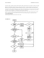
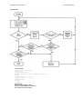
6. Fault-finding information...........................................................................................................25
7. Appendices................................................................................................................................. 30
7.1 Modules/Dealer Serviceable Parts.............................................................................. 31
7.2 Production and Field Changes.................................................................................... 32
7.3 Archimedes Serial Port - Application Note................................................................ 35
7.4 Test Instructions.......................................................................................................... 37
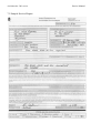
7.5 Sample Service Report................................................................................................73
7.6 Function Map.............................................................................................................. 74
7.7 Plugs and Sockets........................................................................................................75
7.8 Links and Test Points.................................................................................................. 76
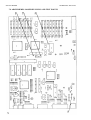
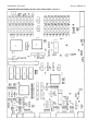
7.9 Main PCB Component Layout....................................................................................77
7.10 Final Assembly Drawing...........................................................................................78
7.11 Lower Case Assembly Drawing............................................................................... 79
7.12 Circuit Diagrams....................................................................................................... 80
Service Manual
Archimedes 300 series
WARNING: THIS COMPUTER MUST BE EARTHED
Important: The wires in the mains lead for the computer are coloured in accordance with the following code:
Green and yellow
Earth
Blue
Brown
Neutral
Live
For United Kingdom users
The moulded plug must be used with the fuse and fuse carrier firmly in place. The fuse carrier is of the same basic colour (though not necessarily
the same shade of that colour) as the coloured insert in the base of the plug. Different manufacturers' plugs and fuse carriers are not
interchangeable. In the event of loss of the fuse carrier, the moulded plug MUST NOT be used. Either replace the moulded plug with another
conventional plug wired as described below, or obtain a replacement fuse carrier from an Acorn Computers' authorised dealer. In the event of the
fuse blowing it should be replaced, after clearing any faults, with a 5-amp fuse that is ASTA approved to BS1362.
For all users
If the socket outlet available is not suitable for the plug supplied, either a different lead should be obtained or the plug should be cut off and the
appropriate plug fitted and wired as noted below. The moulded plug which was cut off must be disposed of as it would be a potential shock hazard if
it were to be plugged in with the cut off end of the mains cord exposed.
As the colours of the wires may not correspond with the coloured markings identifying the terminals in your plug, proceed as follows:
The wire which is coloured green and yellow must be connected to the terminal in the plug which is marked by one of the following: the
letter E, the safety earth symbol, the colour green, or the colour green and yellow.
The wire which is coloured blue must be connected to the terminal which is marked with the letter N, or coloured black. The wire
which is coloured brown must be connected to the terminal which is marked with the letter L, or coloured red.
GUIDELINES FOR SAFE OPERATION
The equipment described in this guide is designed and manufactured to comply with International safety standards IEC65 (BS415) and IEC380 (
BS5850), and is intended for use only as a desktop microcomputer. It should not be used for other purposes. It is most important that unpacking
and installation is carried out in accordance with the instructions given in the Welcome Guide.
The equipment is robustly constructed but in the interests of continued safe and reliable operation, careful handling and the following
guidelines should be observed.
DO keep the machine within a room temperature of 5 to 35 degrees C (41 to 95 degrees Fahrenheit) and a relative humidity of
15% to 95% (non-condensing).
-
DO avoid sudden extremes in temperature, exposure to direct sunlight, heat sources (such as an electric fan heater) and rain.
-
DO make sure that the equipment is standing on a suitable horizontal flat surface, allowing enough space for air to circulate
when the equipment is in use.
DO ensure that wires and cables are routed sensibly so that they cannot be snagged or tripped over. Don't tug or twist any wires or
cables, or use them to hang or lift any of the units.
-
-
DO switch off and unplug the equipment and any accessories before opening any unit, to install an upgrade, for example. The main
computer unit should normally be operated with the cover attached, but it can safely be switched on with the cover removed, provided
that care is taken not to short circuit any connections or to allow any fingers or objects in the area of the fan or disc drives when these
are running. Be especially careful with jewellery. Do not attempt to open any display or monitor unit, whether supplied with this
equipment or not.
DO make sure you have read and understood any installation instructions supplied with upgrade kits before attempting to fit them. If
you have any doubts, contact your supplier.
-
DON'T spill liquids on the machine. If liquid does spill, turn the machine off immediately and take it to your dealer for assessment.
-
DON'T drop the equipment or subject it to excessive bumping and jarring. This is particularly important if you have a hard disc
installed.
-
DON'T poke objects through the ventilation openings in the computer casing, and don't let items such as necklaces or bracelets
drop into the openings.
DON'T exceed a maximum power consumption of 20 watts from the Podule backplane supply.
-
DON'T balance any objects or stand other equipment not designed for the purpose, on top of this equipment.
Archimedes 300 series
Service Manual
1. Introduction
1.1.Nature and purpose of this manual
This manual is intended to provide the information required to diagnose and rectify faults in the Archimedes 300 series
high performance computer system at module level.
The information contained in this manual is aimed at service engineers and Acorn dealers who will be servicing the Archimedes
300 series high performance computer system, at module level, on behalf of Acorn Computers Limited.
Details of service policy are as specified by Acorn Computers Limited in the Service and Support Strategy document.
Reference should be made to the Appendix at the back of this manual for latest Production and Field Change information
prior to servicing.
1.2.Technical Specification
GENERAL
A high performance, microcomputer system, using the Acorn ARM RISC chip set, comprising the ARM (2µ) processor, the
MEMC memory controller, the VIDC Video/Sound controller, and the IOC Input/Output controller.
The 'three-box' system comprises:
A metal cased main unit, with plastic front and rear mouldings, housing the main PCB, a 1 Mbyte (unformatted) 3.5" floppy disc
drive, the PSU and provision for expansion Peripheral Modules (Podules) when the optional backplane and fan are fitted. The
model 305 is fitted with 0.5Mbyte of DRAM and can be upgraded to model 310 specification by the addition of a further 0.
5Mbyte of DRAM.
A 103 key keyboard unit with system reset button, housed in a plastic case. Connection to the main unit is via a coiled-style serial
cable and 6-way miniature circular plug. Function keystrips can be accommodated on the keyboard. The keyboard incorporates
electronics for key scanning, mouse signal decoding and serial data transfer between the keyboard and computer main unit. An
electronically readable 6 bit identification code is included in the keyboard to allow the computer to detect keyboard variants, such
as foreign language versions.
A three-button 'mouse' pointing device connects to the system via a 9-way circular socket on the keyboard. The mouse uses
two quadrature detector encoded signals for each axis of movement with a resolution of 10 edges per mm. In Mode 0, 64mm
of movement traverses the display area - scaling set to 1.
The Archimedes 300 series may be supplied with one of four monitor options:
a.
b.
c.
d.
No monitor
Monochrome - analogue with 256 display lines at 50 Hz (TV format).
Colour - analogue RGB with 256 display lines at 50 Hz (TV format).
Colour - analogue RGB multi-sync type. Monitors automatically lock on to one of two display frequencies
generated by the 300 series:
0 TV format, 256 display lines, 50 Hz non-interlaced.
ii) High resolution mode, 512 display lines, 50 Hz non-interlaced.
NB Colour composite video and UHF/VHF TV outputs are not provided.
COMPUTER MAIN UNIT
RAM Memory , 512K standard, upgradeable to 1 Mbyte total, model 305 1 Mbyte standard,
model 310
120 nS access time
16 off 64K x 4 RAM fitted as standard
16 off 64K x 4 RAM optional upgrade, model 305
The Archimedes 300 series is supplied with 512K of ROM as standard.
Service Manual
ROM Memory
Processor
Real-time clock
Archimedes 300 series
Four 32 pin sockets are fitted. The options are:
128K - 4 off 32K x 8bit ROM/EPROM (eg
27256) 256K - 4 off 64K x 8bit ROM/EPROM (
eg 27512) 512K - 4 off 128K x 8bit ROM (eg
62301 ROM)
24 MHz master clock oscillator. 4/8 MHz ARM (2µ) processor. System
performance is typically 4 MIPS.
Powered by internal batteries when computer switched off
Non-volatile RAM 240 bytes of static RAM which maintains preferred machine configuration, etc.
Powered by internal batteries while the computer is switched off.
Internal batteries Two LR06 (AA size) 1.5 V Manganese Alkaline cells fitted inside computer main
unit. Batteries require replacement once a year.
Controls
Mains on/off switch at rear of unit, integral with PSU.
Floppy disc eject button(s) on front panel.
System reset button (on rear of keyboard unit).
Indicators
Green LED on front panel indicates mains power on.
Amber LED on floppy disc drive(s) indicates drive activity.
Amber LED below power LED indicates hard disc drive activity (where fitted).
Connectors
Power inlet
IEC 320/CEE 22 power inlet connector.
Min.
Nominal
Max.
Operating voltage
range
198
220/240
264 Vac
Frequency
47
50/60
63 Hz
Rating (no monitor)
0.4
A
(with monitor)
0.9
A
Power Outlet
IEC 320/CEE 22 power outlet connector.
Podule Bus
This outlet is unswitched (ie not contolled by the PSU on/off switch) and is live
whenever power is applied to the power inlet. Power rating 3 A max. continuous,
80 A max. surge.
64-way DIN 41612 connector on the main PCB for connection of Podule backplane.
Parallel printer
25-way D type socket.
Serial port
9-way D type plug.
Colour analogue
RGB video
9-way D type socket.
Monochrome
Composite Video
Phono (RCA) socket.
Keyboard
6-way miniature circular socket for keyboard connection.
Mouse
Three-button mechanical mouse connects via a 9-way circular connector on the
keyboard.
Audio
3.5 mm 32 ohm stereo jack socket for output to suitable personal-stereo headphones
or hi-fi system.
DIMENSIONS
Main Unit
Colour
Overall height - 97 mm (excluding feet)
Overall width - 362 mm approx. Overall
depth - 406 mm approx.
Two-tone cream/warm grey
Archimedes 300 series
Finish
Fine texture
Materials
Painted metal
ABS, flame retardent to meet IEC 950
Keyboard
Overall height - 46 mm (excluding feet)
Service Manual
Overall width - 485 mm
Overall depth - 205 mm
Colour
Cream case with warm grey main keys (in two shades) and red function keys.
Finish
Fine texture.
Case material
ABS, flame retardent to meet IEC950
Function keystrip
holder
Clear plastics flame retardent to meet IEC 950.
Weight:
1.75 Kg
OPTIONS - (see Upgrading, section 4, for fitting details)
Podule backplane
and fan
Econet interface
The backplane plugs into the main PCB to enable Podules to be connected via two 64-way DIN
41612 connectors. The fan provides extra cooling required when Podules are fitted.
Plug-in Econet module fits onto main PCB. Econet 5-pin DIN socket fitted as standard (may
be fitted with blanking plug prior to upgrade).
Podules Mechanically identical to single or double width Eurocards, up to two Podules can be fitted at any one time, fitted one
above the other within the rear of the main unit case. If an Econet module is fitted, a half-width only
Podule (or one designed to fit around an Econet module, such as the I/O Podule) can be fitted in the
lower
position. Podules available and planned for the Archimedes system include:
ROM Podule
(AKA05)
Provides a capability for plug-in ROM based software.
I/O Podule (AKA10) Reproduces the BBC Model B/Master Series A to D port, User Port and 1 MHz bus.
MIDI Podule
(AKA16)
Hard disc
Provides a MIDI control interface with music synthesisers.
A MIDI module, AKA15, which can be added to an I/O Podule, is also available.
(part of Hard Disc Upgrade AKD52, see below)
The 300 Series can be fitted with most types of Podule designed for the Archimedes system but Coprocessor Podules, which
need access to the main system data bus, are not supported by the 300 series.
Second Floppy Disc
Drive(AKD50)
A second 3.5" floppy disc drive can be fitted internally as a dealer upgrade. The upgrade consists
of a disc drive, a new data cable assembly and front sub-moulding.
Hard Disc (AKD52) A 20 Mbyte (formatted) 3.5" hard disc can be fitted as a dealer upgrade, together with a Hard Disc
Podule. A Podule backplane and fan is also required.
Either a hard disc upgrade or a second floppy disc upgrade may be fitted.
RAM (AKA51)
A 0.5 Mbyte RAM upgrade can be fitted to model 305 by inserting additional RAM chips, supplied as
a dealer upgrade kit, into the unpopulated sockets on the main unit PCB.
ENVIRONMENTAL
Operating
Temperature
5 to 35° C
Humidity
10% to 95% at 35° C non-condensing
Service Manual
Archimedes 300 series
Altitude
0 to 2500 metres above sea level
Storage
Temperature
-40 to 70° C
Humidity
10 to 95% RH non-condensing
Altitude
Up to 10,000 metres
ELECTRICAL SAFETY
Designed and manufactured to comply with the EEC Low Voltage Directive.
When fitted with PSU intended for 220/240 V operation:
BS415
BS5850
(IEC 65)
(IEC 380)
OPERATING SYSTEM
The Arthur Operating System is described in detail in the Archimedes Programmers' Reference Manual. A summary of the
facilities offered by Arthur is as follows:
Screen modes
Eighteen standard screen modes are supported, with three additional modes designed to take advantage of
multi-sync higher definition monitors. The first eight modes provide compatibility with the BBC
Microcomputer 6502 based range MOS:
Mode
Pixel Resolution
0
1
2
3
4
5
6
7
8
9
10
11
12
13
14
15
16
17
640 x 256
320 x 256
160 x 256
TEXT ONLY
320 x 256
160 x 256
TEXT ONLY
TELETEXT
640 x 256
320 x 256
160 x 256
TEXT ONLY
640 x 256
320 x 256
TEXT ONLY
640 x 256
TEXT ONLY
TEXT ONLY
Logical Colours
2
4
16
2
2
4
2
TELETEXT
4
16
256
80 x 25
16
256
16
256
16
16
The following modes are for use with multi-sync monitors only:
18
640 x 512
2
19
640 x 512
4
20
640 x 512
16
Text
80 x 32
40 x 32
20 x 32
80 x 25
80 x 25
20 x 32
40 x 25
40 x 25
80 x 32
40 x 32
20 x 32
80 x 32
40 x 32
80 x 25
80 x 32
132 x 32
132 x 25
80 x 64
80 x 64
80 x 64
In all modes except Teletext, the colours can be chosen from a palette of 4096 colours, with some
restrictions in the 256 colour modes.
Graphics
Extensions
Modes 16 and 17, together with graphics extensions, enable VT 100 and VT 220 emulations to
be implemented.
The GCOL primitive has been extended to cover transparency and additional raster operations. The
GXR Sprite function has been extended to support WIMPS more fully and to provide BLITTER
functions for animation.
Hardware cursor
8
This is a user-definable 3 colour shape ( a sprite) which can be linked to mouse movement.
Archimedes 300 series
Service Manual
Window manager
This provides a ROM/Operating System based WIMP manager which can be used
by applications programs. It manages up to 32 windows and provides a common
user interface with the mouse across applications.
Alphabets
Five 8-bit (7-bit ASCII + extensions)
Fonts
Command line
interpreter
Debug facilities
Sound
alphabets are included in the ROM. These are based
on ISO 8859 Parts 1, 2, 3, 4 and 7. Parts 1 through 4 support concurrent
wordprocessing, etc in country groupings. Part 7 supports Greek and English.
Optional alphabets based on Cyrillic, Arabic and Hebrew will be available.
Alternative fonts are supported. These are defined in a file and cached as required
in memory. The fonts are proportionally spaced and can cover a wide range of
point sizes. Options for text justification are provided for use by application
programs.
Allows parameters, conditionals, aliasing of commands, system variables and
expressions.
A Monitor program is provided which allows for debugging, ie breakpoints,
disassembler, etc.
Extended features are provided to support the hardware capability. The Operating
System sound code is split into three levels:
Level 0
Level 1
Sound DMA Buffer handler:
Number of channels, sample rate, channel length.
Program number of channels (max. of 8 - default 1)
Enable/disable local speaker
Enable/disable sound system
Program stereo position (max. of 7 positions)
Sound Channel Controller:
Sets loudness amongst many other characteristics.
Level 2 Event Queue manager:
Schedules events related to screen display, etc.
BBC BASIC V
Contains extended functions, including:
WHILE
ENDWHILE
CASE — WHEN — OTHERWISE — ENDCASE IF
— THEN — ELSE
ENDIF
Function and Procedure libraries
Enhanced error handling
Whole array operations
Binary and unary operators
Enhanced TRACE
Improved PRINT accuracy
Re-written string storage
More line numbers and sophisticated tabulation
Full ARM assembler
BASIC editor
6502 Emulation
Code
Advanced Disc
Filing System
An extended version of the Acornsoft 6502 based editor.
This code, which is supplied on the Welcome disc, provides a software
environment in which to execute 'legally' written 6502 code.
An improved version of the 6502-based ADFS. User disc handling has been both
extended and simplified. An additional 800K disc format is added which also
provides a faster access time.
9
Service Manual
Advanced Network
Filing System
Floating Point
Emulator
Archimedes 300 series
An improved version of the 6502-based ANFS, it has been generalised to support a
broader Networking base. Three code modules are included: Econet, NetFS and
NetPrint.
The FPE code is supplied on the Welcome disc. This emulates hardware floating
point units and is used with high level language compilers.
1.3 Packaging and Installation
The computer main unit, keyboard and mouse are supplied in a moulded two-part polystyrene packing in
a cardboard carton. Also included are a Welcome Guide, a Welcome/Utilities disc, a User Guide, a
Keycard set and a guarantee card. An optional colour or monochrome monitor is supplied packed
separately.
Do not use the computer system in conditions of extreme heat, cold, humidity or dust or in places subject
to vibration. Do not block the ventilation slots in the main unit casing. Ensure that no foreign objects are
inserted through any openings in the casing.
Archimedes 300 series
Service Manual
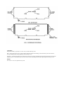
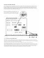
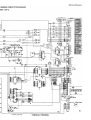
2. System Description
Introduction
The Archimedes 300 series is built around the A Series chip set, comprising theAcorn Risc Machine (
ARM), the Memory Controller (MEMC), Video Controller (VIDC) and Input Output Controller (IOC).
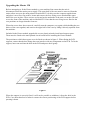
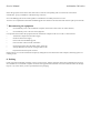
A schematic of the Archimedes 300 series is shown below:
General
The ARM (Acorn Risc Machine) IC is a pipelined, 32 bit reduced instruction set microprocessor which
accepts instructions and manipulates data via a high speed 32 bit data bus and 26 bit address bus giving a
64 MByte uniform address space. The ARM supports virtual memory systems using a simple but powerful
instruction set with good high-level language compiler support.
The Memory Controller (MEMC) acts as the interface between the ARM, the Video Controller, I/O
Controllers, Read-Only Memory (ROM) and Dynamic memory devices (DRAM), providing all the
critical system timing signals including processor clocks.
1 MByte of DRAM (0.5 MByte in model 305) is connected to MEMC which provides all signals and
refresh operations. A Logical to Physical Translator maps the Physical Memory into a 32 MByte Logical
address space (with three levels of protection) allowing Virtual Memory and Multi-Tasking operations to
be implemented. Fast 'page mode' DRAM accesses are used to maximise memory bandwidth. The VIDC
requests data from the RAM when required and buffers it in one of three FIFOs before using it. Data is
requested in blocks of four 32-bit words, allowing efficient use of paged-mode DRAM without locking
the system data bus for long periods.
MEMC supports Direct Memory Access (DMA) operations with a set of programmable DMA Address
Generators which provide a circular buffer for Video data, a linear buffer for Cursor data and a double
buffer for Sound data.
The Video Controller (VIDC) takes video data from memory under DMA control, serialises it and passes
it through a colour look-up palette and converts is to analogue signals for driving the CRT guns. The
11
Service Manual
Archimedes 300 series
VIDC also controls all the display timing parameters and controls the position and pattern of the cursor sprite. In addition, it
incorporates an exponential Digital to Analogue Converter (DAC) and stereo image table for the generation of high quality sound
from data in the DRAM.
The VIDC is a highly programmable device, offering a very wide choice of display formats. The colour look-up palette which
drives the three on-chip DACs is 13 bits wide, offering a choice from 4096 colours or an external video source.
The cursor sprite is 32 pixels wide and any number of rasters high. Three simultaneous colours (again from a choice of 4096) are
supported and any pixel can be defined as transparent, making possible cursors of many shapes. It can be positioned anywhere on
the screen. The sound system implemented on the device can support up to 8 channels, each with a separate stereo position.
The Input Output Controller (IOC) controls the IO bus, expansion Podules and provides basic functions such as the keyboard
interface, system timers, interrupt masks and control registers. It supports a number of different peripheral cycles and all IO
accesses are memory mapped.
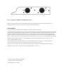
The I/O system
The I/O system is controlled by the I/O Controller IOC and the Memory Controller MEMC. The I/O Bus supports all the internal
peripherals and the PODULE expansions. It is important to realise that it is up to the machine operating system, in conjunction with
the Podule ID, to determine the address at which a Podule should be accessed.
System Architecture
The I/O system (which includes Podule devices) consists of a 16 bit data bus (BD[0:15]) a buffered address bus (LA[2:21]) and
various control and timing signals. The I/O data bus is independent from the main 32-bit system data bus, being separated from it
by bidirectional latches and buffers. In this way the I/O data bus can run at much slower speeds than the main system bus to cater
for slower peripheral devices. The latches between the 2 buses and hence the I/O bus timing are controlled by the I/O controller,
IOC. The IOC caters for 4 different cycle speeds (slow, medium, fast and synchronous).
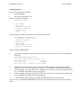
A typical 300 series I/O system with 'simple' Podules fitted is shown in the diagram below. The Podules are controlled by IOC.
For clarity, the data and address buses are omitted from this diagram.
12
Archimedes 300 series
Service Manual
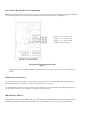
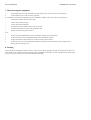
System Memory Map
The system memory map is defined by the MEMC, and is shown below. Note that all system
components, including I/O devices, are memory mapped.
The Sound System
The sound system is based on the VIDC stereo sound hardware. External analogue anti-alias filters are
used which are optimised for a 20 kHz sample rate. The high quality sound output is available at a 3.5mm
stereo jack socket at the rear of the machine which will directly drive personal stereo headphones or
alternatively an amplifier and speakers. A mono mix of the sound output is sent to the internal loudspeaker.
13
Service Manual
Archimedes 300 series
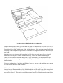
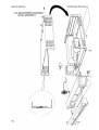
3. Disassembly and Assembly
The main unit houses the main PCB, the PSU and 3.5" floppy disc drive. Provision is made for the installation of a second
floppy disc drive or hard disc unit plus a variety of Podules via a backplane board. A cooling fan may also be fitted with
some upgrades.
The keyboard, mouse and monitor are separate units. See the appropriate third-party service information for the monitor. The
mouse is a service replacement only item.
Main Unit
DISASSEMBLY
1.
Disconnect the computer from the mains supply and all peripherals, including the keyboard.
2.
Place the main unit, with the rear panel facing you, on a worksurface with a clean, soft covering.
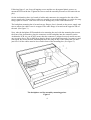
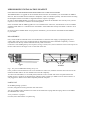
3.
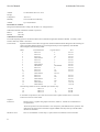
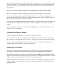
Remove the top cover as follows (see fig. 1):
Remove the two screws in the sides of the top cover, immediately behind the front moulding.
Remove the three screws along the top of the rear panel and remove the top cover by sliding it off from the rear of the
unit.
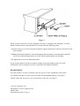
4.
To remove the main PCB: Unplug the following cables from the main
PCB (see fig. 2):
Speaker/LED connector PL9.
Battery connector PL11.
Fan connector PL12 (if fitted).
Four power tags - PL5 (yellow,
+12V), PL6 (black, 0V), PL7 (red, +5V) and PL8 (mauve, -5V).
Archimedes 300 series
Service Manual
5.
Unplug the floppy disc drive cable from SK11 on the main PCB. If a hard disc drive is fitted,
unplug the 34-way (PL3) and 20-way (PL4) connectors from the Hard Disc Podule.
6.
Unplug and remove any Podules fitted - see the relevant upgrade instruction in section 4, "
Upgrading".
7.
Unplug and remove the Podule backplane (if fitted) - see the relevant upgrade instruction in
section 4, "Upgrading".
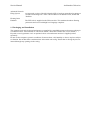
8.
Stand the unit up on its left side and remove the two screws and star washers from the underside
securing the rear bus bars (see fig. 3).
9.
Remove the 3 screws from the underside securing the rear moulding.
10. Stand the unit back on its feet and begin to withdraw the rear moulding, with the main PCB
attached, out of the case. Support the front edge of the PCB as soon as it is accessible.
The optional cooling fan is mounted against the front left side of the casing (viewed from the front),
alongside the battery holder. See section 4.4 for details.
FLOPPY DISC DRIVE
A single internal floppy disc drive is fitted as standard. To remove the drive, follow steps 1, 2 and 3 above
in "Main Unit Disassembly" to gain access to the interior of the main unit. With reference to Figure 4,
unplug the drive data ribbon cable from SK11 on the main PCB and the power cable connector from the
rear of the drive. Locate and remove the two screws securing the disc drive mounting bracket to the saddle
bracket and carefully withdraw the disc drive assembly from the main unit.
Before installing a replacement drive, remove the front facia which is supplied clipped to the drive and fix
the eject button to its shaft using cyanoacrylate adhesive (observe safety precautions on the adhesive
pack).
Partially insert a disc before carefully placing the drive assembly in position. Guide the disc through the
slot in the moulding and adjust the position of the drive until the eject button passes through its slot in the
moulding. Insert and partially tighten the two drive bracket fixing screws. Push the disc fully into the drive.
Check that the drive will accept and reject discs and that the eject button does not bind on the moulding.
Adjust the position of the drive mounting bracket if necessary, then finally tighten the fixing screws.
For access to front case moulding assemblies, front panel LEDs and speaker, see the relevant disc drive
upgrade instructions in section 4, "Upgrading".
Service Manual
Archimedes 300 series
POWER SUPPLY UNIT
CAUTION: DOUBLE POLE/NEUTRAL FUSING
The PSU is fitted with a double-pole switch and both the Live and Neutral lines are fused.
To remove the PSU, ensure that all low voltage captive leads are disconnected and free from restraints. Remove the fan (if fitted)
then remove the four M3 x 6 mm fixing screws from the underside of the base metalwork. Slide the PSU forward to clear the rear
moulding, then lift it clear. When installing a PSU, the system should be tested for satisfactory earth continuity in accordance with
IEC 950*.
NOTE: THE PSU IS A SERVICE REPLACEMENT ONLY ITEM.
*IMPORTANT NOTE
WHEN REFITTING OR FITTING A REPLACEMENT ASSEMBLY, CHECKS SHOULD BE
MADE FOR EARTH CONTINUITY BETWEEN THE EARTH PIN OF THE MAINS PLUG
AND THE FOLLOWING:
THE BASE METALWORK
THE REAR PANELS (INCLUDING BLANKING PANELS)
THE TOP COVER
USE AN EARTH CONTINUITY TESTER SET TO 25 AMPS.
MAIN UNIT ASSEMBLY
Assembly is generally the reverse of the disassembly procedures, but take care with routing of cables and ensure that leads are not
trapped when refitting assemblies to the main unit.
Keyboard
Two types of keyboard have been used in production - known as Keyboard Products (KPL) and Keytronics. These units house
PCBs which are electrically compatible but physically different in construction. The two types are distinguished externally by the
position of the LED in the Scroll Lock key; the KPL keyboard has this LED in the top left of the keytop, whilst on the Keytronics
version it is in the top right corner. Keyboard PCBs must be replaced on a like-for-like basis, as follows:
DISASSEMBLY - SEE FIG. 5
Invert the keyboard and place it on a soft, level surface. Remove the eight Pozidriv screws securing the two halves of the case
and carefully lift the base moulding away.
For a KPL PCB, remove the three No. 6 x ¼" Pozidriv screws (A, B and C) securing the board to the top moulding and carefully
lift the board clear. Note that seven plastic spacers are placed over the fixing bosses in the top moulding; three are clamped by the
board fixing screws, whilst two at each end support the board without fixing screws. Ensure that the spacers are located correctly
before replacing the PCB into the moulding.
The Keytronics board is fixed to the top moulding by four No. 6 x 1/4" screws, two at each end of the metal PCB support tray
plus, on some units, three further screws at A, B and C as for the KPL Keyboard. Remove the three extra screws first, if fitted,
then remove the two screws from the end nearest to the keyboard cable. Loosen the two remaining srews and lift the board clear.
Note that the reset switch cap must be removed from the original keyboard and fitted to the replacement.
ASSEMBLY
Keyboard assembly is generally in reverse order, with the following notes:
KPL - ensure all the spacers are in position before fitting the PCB to the moulding. Check that all keys clear the cutouts in
the top moulding before finally tightening all PCB fixing screws.
Keytronics - Slot the PCB support tray under the two fixing screws at the end furthest from the Keyboard cable, then insert the
remaining screws. Check that all keys clear the cutouts in the top moulding before finally tightening all PCB fixing screws.
Mouse
The mouse is a service replacement only item.
Service Manual
Archimedes 300 series
4. Upgrading
Any modification or upgrade carried out to the printed circuit board of any Acorn equipment is undertaken at the sole risk of the
person carrying out the modification or upgrade. No claim for loss or damage to the equipment caused by the modification or
upgrade by unskilled personnel shall be accepted by Acorn Computers Ltd.
Before commencing an upgrade, please read all of the instructions carefully. If you are in doubt about your ability to carry it
out, the upgrade kit and computer should be taken to your nearest authorised Acorn dealer.
A charge may be levied by the dealer for installing the upgrade in the machine, such a charge shall be entirely at the discretion
of the dealer.
The following are copies of the actual upgrade instructions. These instructions are the latest issues at the time this manual was
prepared.
The backplane, podule, second floppy disc drive and MIDI module installation leaflets, together with the Arthur ROM fitting
instruction, are supplied with the upgrade kits, giving instructions for fitting the upgrade by the user.
The hard disc upgrade leaflet is supplied with the kit and gives user information on the use and care of the hard disc.
The hard disc and RAM upgrade kit fitting instructions are supplied to dealers only for dealer-fitted upgrades.
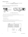
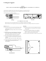
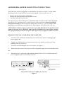
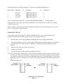
BACKPLANE INSTALLATION LEAFLET
For use with the Archimedes High Performance Computer System
Any Podule is installed by plugging it into an adapter, inside the Archimedes, called the `
backplane'. This leaflet describes how to install the backplane as well as a cooling fan which is
included with the kit. It is essential that the fan is fitted at the same time as the backplane to
ensure that the machine remains within its specified operating temperature range.
The backplane fitting kit should contain the following parts.
For the backplane:
1 backplane PCB
1 mounting bar
2 hexagonal plastic spacers
4 self-tapping screws to fit the spacers
2 straight screws to locate the mounting bar
1 tie-wrap
For the fan assembly:
1 fan unit
1 filter clamp
1 fan filter
4 bolts and 6 nuts to locate the fan and filter
If any of these parts is missing then consult your supplier.
Fitting the backplane necessitates removing the lid of the Archimedes. The only tools required to
do this are a medium Posidriv screwdriver (which is also needed to locate the mounting bar, the
backplane PCB and the fan unit) and a M4 spanner. If you are not confident of fitting the
backplane yourself, then please take your Archimedes and the backplane fitting kit to your
dealer who will fit it for you.
WARNING
Ensure that the Archimedes is switched off at the rear and that the mains supply cable is
disconnected from the mains before removing any covers.
Under normal operation, hazardous voltages exist in the power supply unit. Do not push, dangle
or drop objects through the ventilation holes of the PSU case.
If for any reason, the PSU is removed from the casework, then on reassembly, the system
should be tested for satisfactory safety earth continuity as detailed in the Archimedes Service
manual.
1
DISASSEMBLY
First, make sure that the Archimedes is disconnected from the mains by unplugging the power supply cable,
and remove any peripherals (including the keyboard) that are attached. Clear the Archimedes completely, that
is, remove any monitor from on top and any other loose items.
The top case is held by three screws at the top rear of the unit and one screw on each side of the unit. These must
be removed. The position of these screws are shown in figure 1.
Once you have removed the five screws, the lid of the unit will slide back and off. Remove the lid from the unit
completely.
The backplane can now be fitted.
2
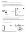
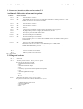
FITTING THE BACKPLANE
The first task is to affix the backplane PCB to the backplane mounting bar using the
hexagonal plastic spacers and the four self-tapping screws.
It is vital to get the PCB and the mounting bar in correct relation to one another, and to use
the correct two holes in the mounting bar. (See figure 2.)
The correct relation of the mounting bar and the backplane PCB
Figure 2
Following figure 2, use four self-tapping screws and the two hexagonal plastic spacers to
mount the PCB on the bar. Tighten the screws until the assembly becomes a firm unit with no
play.
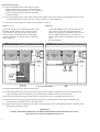
On the Archimedes, there is a bunch of cables and connectors tie-wrapped to the side of the
power supply unit. Some of these cables are needed to power the backplane, so cut the tie-wrap
using a pair of scissors. Take care not to cut or damage any of the cables themselves.
The backplane mounting bar is located on two flanges. One is located on the power supply unit
near to where the cables were tie-wrapped. The other flange is located on the opposite side of
the unit. (See figure 3.)
Next, take the backplane PCB attached to its mounting bar and, with the mounting bar nearest
the front of the Archimedes, plug the connector on the backplane into the connector on the
Archimedes PCB. As you do this, ensure that the connector is aligned correctly and do not use
any excessive force. If it is difficult to plug in, then it is not aligned correctly, so remove it and
start again. Be careful that the mounting bar does not snag on any of the cables that you have
just freed. All the cables must be loose and in front of the mounting bar. (See figure 3.)
The backplane and fan assembly mounting points
Figure 3
4
When the backplane is located on the Archimedes PCB, the backplane mounting bar should line
up fairly closely with the flanges on the Archimedes. Use the two straight screws supplied and
gently manipulate the Archimedes lower case and the backplane mounting bar until they locate
through the bar and into the holes below. Tighten up the screws in such a position as the
backplane PCB is as near vertical as possible. The holes in the backplane mounting bar are oval
for this purpose.
Take the black single wire from the bunch that was freed and connect it to the tag on the
backplane PCB labelled OV.
Take the red single wire and connect it to the tag on the backplane PCB labelled +5V.
Take the yellow single wire and connect it to the tag on the backplane PCB labelled
+12V.
If a hard disc drive is already fitted to the Archimedes then the installation of the backplane is
now complete.
If a hard disc drive is not fitted then the power supply cable used for it is still hanging free.
This cable, which has a large plastic-covered connector on the end, must be tied out of harm's
way to the backplane mounting bar using the new tie-wrap supplied. Make sure that there is no
way that the live pins in the connector can come into contact with any surface in the
Archimedes, such as the power supply unit, or the PCB, or the backplane mounting bar itself.
The backplane unit is now installed.
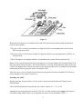
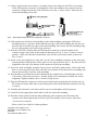
FITTING THE FAN ASSEMBLY
The fan assembly locates on the left side of the Archimedes, just in front of the power supply
unit. There are four holes in the case arranged in a square pattern. The fan assembly locates on
four bolts through these holes. (See figure 3.)
First, examine the fan unit itself. There are two arrows inscribed on its case, one showing the
direction of rotation, and one showing the direction of airflow. The arrow indicating the
direction of airflow must point into the Archimedes case when the fan is installed.
Take the four bolts and insert them, from the outside, into the four holes. Place one hand over
all four bolt heads to stop them from being pushed out.
Take the fan unit and, ensuring that it is the correct way round as described above, pass
its mounting holes over the four bolts which protrude into the case.
Put a nut on each bolt, and, holding each nut in turn with one hand, use the Posidriv screwdriver
to tighten the bolt from the outside.
5
Next, take the fan filter and pass it over the four bolts, being careful not to tear it. Locate the filter so that the nuts
fit through the cutouts and the filter is flush against the face of the fan.
Take the filter clamp and pass this over the four bolts. Fit the two remaining nuts on to the top right and bottom
left bolts (as viewed from inside the machine). Tighten the nuts, using an M4 spanner. Be careful not to trap the
filter material between the filter clamp and the four fan-fixing nuts.
Finally, plug the power supply connector from the fan lead on to the connector labelled PL12 on the Archimedes
PCB. This connector will only engage correctly one way round.
The fan assembly is now installed.
REASSEMBLY
Once the backplane and fan unit are correctly installed, slide the top case of the Archimedes on from the rear,
making sure that it is correctly located in the two slots, one on each side of the lower case.
First replace the three screws at the rear of the unit and tighten them up. (See figure 1.)
Finally replace the two screws, one on each side of the case and tighten them up. (See figure 1.)
REPLACING THE FAN FILTER
To replace the fan filter, proceed as follows:
- undo the two M4 nuts retaining the filter clamp
- remove the clamp and filter
- replace the filter with a new one
- refit the clamp and the two M4 nuts
©Acorn Computers Limited
Published by Acorn Computers Limited
March 1988
Part number 0476,040, Issue 2
8
ECONET MODULE FITTING INSTRUCTIONS
FOR USE WITH MASTER 128, MASTER COMPACT AND ARCHIMEDES
300/400 SERIES
These instructions explain how to install an Econet module into a Master 128, Master Compact
and Archimedes 300/400 series microcomputer. After reading the Introduction you should then
refer to the part of the instructions relevant to your machine.
INTRODUCTION
Any modification or upgrade carried out to the printed circuit board of any Acorn equipment is
undertaken at the sole risk of the person carrying out the modification or upgrade. No claim for
loss or damage to the equipment caused by the modification or upgrade by unqualified personnel
shall be accepted by Acorn Computers Limited.
Before commencing an upgrade please read all of the instructions carefully. If you do not feel
confident to carry out this upgrade then take the upgrade kit and your computer to an Acorn
Computers' authorised dealer for upgrade installation.
A charge may be levied by the dealer for installing the Econet upgrade in your machine, such a
charge shall be entirely at the discretion of the dealer.
IMPORTANT: Most electronic devices can be damaged by static electricity. To
reduce the possible adverse effects of static electricity note the following points when
installing any component(s) or upgrade:
• avoid personal static charge where possible
• avoid working in areas where there are manmade fibres, eg nylon carpets and
nylon clothing
• after the computer is disconnected from the mains, touch the metalwork of the
case while performing the upgrade to ensure that you and the computer are at an
equal potential
• keep the IC(s) in anti-static foam until fitted
• avoid touching the pins of the IC(s) during fitting
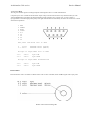
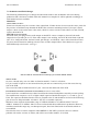
This upgrade may require the installation of a ROM into your computer. It is important to be able to
identify pin one on the ROM so that it can be installed in the correct orientation. Pin one is
indicated in one of two ways. Either a small dot or dimple is placed directly above pin one, or a
horseshoe shaped indentation is cut into the pin one end of the IC with pin one always being to the
left of the indentation. In some instances both of these indicators will be present.
ARCHIMEDES 300/400 SERIES
Disassembly
To remove the top cover of the Archimedes, proceed as follows:
1 Switch the computer off and disconnect it from the mains supply by unplugging the power
supply cable.
2 Disconnect and remove all peripherals, including the keyboard and the monitor.
3 Place the computer, with the rear panel facing you, on a worksurface with a clean, soft
covering.
4 Locate and remove the three screws along the top of the rear panel.
5 Locate and remove the two screws (one in each side of the top cover) immediately behind the
front moulding.
6 Remove the top cover by sliding it off from the rear of the computer.
Installing the Econet module
Included in the Econet module upgrade kit are two plastic printed circuit board support posts.
These must be fitted to the main printed circuit board before installing the Econet module.
The positions at which these posts are to be fitted are shown in figure 1.
When fitting the PCB supports, ensure that the base flange does not interfere with any component
on the PCB. To fit the support, insert one end into the hole in the PCB and press down gently.
When the PCB supports are installed on the main PCB, the Econet module should be placed in
position ensuring that:
1 The pins of PL1 on the Econet module are aligned with the corresponding holes in the socket
SK5 on the main PCB.
2 The pins of PL2 on the Econet module are aligned with the corresponding holes in the socket
SK6 on the main PCB.
3 The PCB supports are aligned with the corresponding holes on the Econet module PCB.
When you are satisfied that all the pins and supports are correctly aligned, the Econet module PCB
may be pressed gently into place. The Econet module is correctly seated when the barbs on the tips
of the PCB supports have cleared the surface of the Econet module PCB. An audible click should be
heard when the barbs spring into place securing the PCB.
Take care not to exert too much pressure when pressing home the Econet module PCB, this may
lead to damage of the various connectors.
Visually check that all is well and re-assemble the computer unit by refitting the top cover and
inserting the five fixing screws, three in the rear panel and one at each side of the computer.
Network Software
The ANFS ROM supplied with the Econet module upgrade is not required in the Archimedes. An
enhanced version of the ANFS software is incorporated into the Arthur operating system ROM
already installed in the Archimedes 300/400 series.
The Archimedes is now ready to be connected to an Econet network. See your Network Manager
who will assign and set your station number.
If you have a version of the Arthur operating system earlier than 1.2 then contact your supplier for
information on how to obtain an upgrade
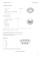
MASTER 128 AND MASTER COMPACT MICROCOMPUTERS
Machine orientation
Within this fitting instruction, the points of the compass are used to indicate the way in which
components are oriented. With the machine positioned such that the keyboard is nearest you and
uppermost, the nearest edge is designated to be SOUTH, the rear NORTH and right and left are
designated EAST and WEST respectively.
The Econet module will be installed in the NORTH-EAST corner of the printed circuit board on
both the Master 128 and Compact machines.
Upgrading the Master 128
Before attempting to fit the Econet module to your machine first ensure that the unit is
disconnected from the mains power supply. The upper half of the case must be removed from the
unit to allow access to the main printed circuit board. To do this, turn the computer upside down
and place it on a firm, flat surface; locate and remove the four fixing screws that hold the upper
half of the case in place. These screws are located on the underside of the unit, two at the rear and
two at the front of the machine, and are labelled FIX. Note that the two fixing screws fitted to the
rear positions are longer than the front two.
When the screws have been removed, carefully turn the computer over again (whilst holding the two
halves of the case together) and remove the upper half of the case by lifting it directly upwards from
the machine.
Included in the Econet module upgrade kit are two plastic printed circuit board support posts.
These must be fitted to the main printed circuit board before installing the Econet module.
The positions at which these posts are to be fitted are shown in figure 2. When fitting the PCB
supports, ensure that the base flange does not interfere with any component on the PCB. To fit the
support, insert one end into the hole in the PCB and press down gently.
Figure 2
When the support is correctly fitted, it will not be possible to withdraw it from the hole in the
PCB. Care must therefore be taken to ensure the correct positioning of the PCB support before
pressing it home.
When the PCB supports are installed on the main PCB, the Econet module should be placed in
position ensuring that:
1
The pins of PL1 on the Econet module are aligned with the corresponding holes in socket SK5
on the main PCB. The two WEST most holes of SK5, labelled 'A' and 'B', are not used.
2
The pins of PL2 on the Econet module are aligned with the corresponding holes in socket SK6
on the main PCB.
3
The PCB supports are aligned with the corresponding holes on the Econet module PCB.
When you are satisfied that all the pins and supports are correctly aligned, the Econet module PCB
may be pressed gently into place. The Econet module is correctly seated when the barbs on the tips
of the PCB supports have cleared the surface of the Econet module PCB. An audible click should be
heard when the barbs spring into place securing the PCB.
Take care not to exert too much pressure when pressing home the Econet module PCB, this may
lead to damage of the various connectors.
Installing the ANFS
Having fitted the Econet module, it is necessary to fit the Advanced Network Filing System (
ANFS) ROM.
The ANFS ROM must be inserted into one of three sockets, IC27,37 or 41. It is recommended that
socket IC27 should be used where possible. If it is not possible to use socket IC27 then one of the
other two sockets may be used, but it will be necessary to change the position of a link on the main
PCB (see NOTE 1).
To insert the ANFS ROM, hold the ends of the IC between thumb and forefinger, and line up all the
pins over the destination socket. The pin one end of the IC should face to the WEST. If you are
unsure of which way round the IC should be installed, refer to the other ICs on the main PCB which
all face WEST.
Apply firm pressure to the IC, but do not force it. When the chip is in place it may appear to be
slightly raised. Check that all the pins have entered the socket and that none are bent either
outwards or under the body of the IC.
When the Econet module PCB and the ANFS ROM have been installed, the re-assembly
procedure is the reverse of the dismantling procedure.
Setting the station number
Before attempting to add a machine to an existing Econet, the station number must be set. The
Network Manager should be asked to carry out this operation.
NOTE 1:Sockets IC37 and 41 share the same address space as four sideways RAM
pages. The position of links LK18 and LK19 determine whether the address space is
claimed by ROM or sideways RAM.
5
These two links are located close to the WEST side of ICs37 and 41, LK18 is used with IC41 and
LK19 is used with IC37. These links consist of a three pin plug with a connector which may be
push fitted onto two pins of the plug to make a connection. There are two possible positions for
this connector:
EAST - the connector joins the central pin to the right hand pin (enables sideways ROM)
WEST - the connector joins the central pin to the left hand pin (enables sideways RAM)
The use of one of the sockets with a ROM will preclude the use of 32K (two 16K pages) of
sideways RAM. If both IC37 and IC41 are used in conjunction with sideways ROMs, all four of
the 16K sideways RAM pages will be unavailable.
If IC27 is already occupied and you need all four pages of sideways RAM, you will need to fit the
ANFS ROM into an EPROM cartridge which can then be plugged into one of the cartridge
sockets.
Further information about the use of sideways RAM/ROM may be obtained from Part 1 of the
Master 128 Reference Manual.
Upgrading the Master Compact
Unplug all peripherals and remove the power lead from the computer.
Lay the computer face down on a flat surface and undo the four case fixing screws. Gently turn
the computer over allowing the screws to fall free. Put them in a safe place until required again.
Lift the top case including keyboard away from the base of the computer - (taking care not to
strain the ribbon cable) and lay it in front of the machine.
Installing the Econet Module
Included in the Econet module upgrade kit are two plastic printed circuit board support posts.
These must be fitted to the main printed circuit board before installing the Econet module.
The positions at which these posts are to be fitted are shown in figure 3. When fitting the PCB
supports, ensure that the base flange does not interfere with any component on the PCB. To fit the
support, insert one end into the hole in the PCB and press down gently.
When the support is correctly fitted, it will not be possible to withdraw it from the hole in the
PCB. Care must therefore be taken to ensure the correct positioning of the PCB support before
pressing it home.
Figure 3
When the PCB supports are installed on the main PCB, the Econet module should be placed in
position ensuring that:
1 The pins of PL1 on the Econet module are aligned with the corresponding holes in the socket
SKT4 on the main PCB.
2 The pins of PL2 on the Econet module are aligned with the corresponding holes in SKT5 on
the main PCB.
3 The PCB supports are aligned with the corresponding holes on the Econet module PCB.
When you are satisfied that all the pins and supports are correctly aligned, the Econet module PCB
may be pressed gently into place. The Econet module is correctly seated when the barbs on the tips
of the PCB supports have cleared the surface of the Econet module PCB. An audible click should be
heard when the barbs spring into place securing the PCB.
Take care not to exert too much pressure when pressing home the Econet module PCB, this may
lead to damage of the various connectors.
Installing the ANFS
Having fitted the Econet module, it is necessary to fit the Advanced Network Filing System (
ANFS) ROM.
The ANFS ROM should be inserted into one of three sockets, IC 17, 23, or 29.
Although it may be inserted into socket IC38 if PL11 is made South (refer to figure 3) it must be
noted that fitting ANFS in this way will disable selection of external ROMS via PL13.
7
To insert the ANFS ROM, hold the ends of the IC between thumb and forefinger, and line up all the
pins over the destination socket. The pin one end of the IC should face to the WEST. If you are
unsure of which way round the IC should be installed, refer to the other ICs on the main PCB which
all face WEST.
Apply firm pressure to the IC, but do not force it. When the chip is in place it may appear to be
slightly raised. Check that all the pins have entered the socket and that none are bent either
outwards or under the body of the IC.
When the Econet module PCB and the ANFS ROM have been installed, the re-assembly
procedure is the reverse of the dismantling procedure.
Your Master Compact is now ready to be connected to a network, see your Network Manager who
will assign and set your station number.
©Acorn Computers Limited
Published by Acorn Computers Limited
November 1987
Part Number 0459,200, issue 2
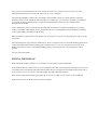
PODULE INSTALLATION LEAFLET
For use with the Archimedes High Performance Computer System
To install a Podule in the Archimedes you will require an adapter called a `backplane'. The backplane is
available separately and must be installed before you attempt to install the Podule. Full instructions for installing
the backplane are supplied with it.
In order to fit the Podule you will have to remove the lid of the Archimedes and one of the blanking plates at the rear
of the machine. The only tools you will require for this are a No. 1 and a No. 2 Posidriv screwdriver. If you do not
feel confident about performing this operation, you can take the computer and the Podule to your dealer.
DISASSEMBLY
First, disconnect the Archimedes from the mains by unplugging the power supply cable. Then, remove any
peripherals that are attached and clear the Archimedes completely, ie remove any monitor from the top of the
Archimedes and any other loose items.
Locate the screws holding the top case in place (see figure 1). First, remove the three screws at the top rear of the
unit. Then remove the single screw on each side of the unit.
The position of the screws holding the top case.
Figure 1
Once you have removed the three rear screws and the two side screws, slide the top cover to the rear of the
machine and then slide it off. You should remove the top cover completely.
Check that the backplane is fitted to the Archimedes. The backplane consists of a small printed circuit board
mounted vertically on the main PCB. If the backplane is not fitted, then you will have to purchase one and install
it, according to the instructions which are supplied with the backplane, before you can continue with the
installation of the Podule.
On the Archimedes 300 series, the optional backplane has two Podule slots capable of holding up to two single
width or two double width Podules. On the Archimedes 400 series, the backplane (fitted as standard) can hold up
to four single width or two double width Podules.
If the backplane is fitted, but has no free Podule slot, you will have to remove one of the Podules in order to install
the new one.
The backplane has an upper and lower Podule slot(s). These correspond to the two full-width blanking plates fitted
to the unexpanded machine. Each blanking plate is held in place by screws, one at each end. Choose one of the
Podule slots and remove the corresponding blanking plate by unscrewing the two screws holding the plate in
position.
You can now fit the Podule.
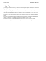
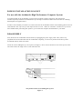
FITTING THE PODULE
Before fitting the Podule, examine it to see whether it is a full-width or a half-width Podule.
A full-width Podule has a plate at the rear which extends the full width of the Archimedes. If the plate on the rear of
your Podule does not extend the full width of the machine then you are supplied with a blanking plate along with a
T-piece and two screws. Use these to make the Podule up to full width of the machine.
Once you have made the backplate of the Podule up to the correct width, you can install it in the Archimedes.
Figure 2 shows where the Podule locates on the Archimedes.
Locating points of BBC I/O Podule on Archimedes
Figure 2
Support the backplane firmly with one hand and push the connector on the Podule into one of
the sockets on the backplane. The connector should be securely seated, ie the rear plate of the
Podule should be flush with the rear of the Archimedes case. It is important that you offer the
Podule up to the backplane at right-angles to it and that you align the connectors, otherwise, you
may bend
the pins or break or disconnect the backplane itself. It does not require great force to install
the Podule correctly. If the Podule will not seat easily, remove the Podule and start again.
When you have fitted a backplane and Podule to your Archimedes, you should find that the
backplane is vertical, assuming that the Podule is fully inserted and screwed to the rear of
the Archimedes.
For some combinations of machines and Podules, however, the top of the backplane may appear
to `lean' towards the front of the machine.
If this is the case, you must insert the two spacers found in this package. Each spacer should be
inserted between the internal face of the Podule backplate and the metal clips on the rear plastic
moulding of the machine, so that the fixing screws pass through both the backplate and the
spacers (see figure 3). This should result in the external face of the Podule backplate panel being
flush with the rear of the machine plastic.
Figure 3
When you have done this, you may find that you need to 'straighten' the backplane, to ensure
that the connectors are correctly mated. To do this, take the following steps:
1 Slacken off the two screws fixing the backplane support metalwork to the base metalwork and
power supply.
2 Holding the Podule stationary, ease the backplane back towards a vertical position until the
faces of the interlocking connectors on the Podule and backplane are touching.
3 Re-tighten the two screws slackened earlier.
If you do not require to fit the two spacers, simply secure the Podule to the rear of the
Archimedes case by inserting a screw at each end of the Podule backplate.
REASSEMBLY
Once the Podule is correctly installed, slide the top case of the Archimedes on from the
rear. Replace the three screws at the rear of the unit and tighten them up. See figure 1.
Finally replace the two screws, one on each side of the case. See figure 1.
©Acorn Computers Ltd
Published by Acorn Computers Ltd
March 1988
Part number 0476201, Issue 2
High Performance Computer Systems
Model 305 0.5 Mbyte RAM Upgrade Kit
AKA 51
Fitting Instructions
Copyright Acorn Computers Limited 1987.
Neither the whole or any part of the information contained in, or the product described in, this manual
may be adapted or reproduced in any material form except with the prior approval of Acorn Computers
Limited (Acorn Computers).
This manual is for the sole use of Acorn Computers' authorised dealers and must only be used by them
in connection with the product described within.
First Published 1987
Published by Acorn Computers Limited
Part No. 0476,051
Issue 3
March 1988
Contents
1. Introduction
2. Upgrade Kit List
3. Fitting the Upgrade
1. Introduction
This document details the installation of an additional 0.5 Mbyte of RAM in an Archimedes model
305, thereby upgrading it to a model 310.
The kit includes all the components needed to complete the installation in model 305 machines.
IMPORTANT: Any machine configurations currently stored in the CMOS RAM may be lost during this upgrade. Refer to the
Archimedes Service Manual, section "Test Instructions" for details of how to save and reinstall machine configuration before
starting the upgrade.
2. Upgrade Kit List
Item Part No.
Description
Qty
1
0704,105
IC 4464 DRAM
16
2
0276,071
Label, 310 (Hard disc)
1
3
0276,315
Label, 310
1
3. Fitting
the Upgrade
WARNING
TAKE ALL PRECAUTIONS REGARDING STATIC ELECTRICITY AND EARTHING
IN ACCORDANCE WITH B.S. 5783.
1. Disconnect the computer from the mains supply and all peripherals, including the keyboard.
2. Place the unit, with the rear panel facing you, on a worksurface with a clean, soft covering.
3. Remove the top cover as follows (see fig. 1):
FIG. 1 REMOVING THE TOP COVER
Remove the two screws in the sides of the top cover, immediately behind the front moulding.
Remove the three screws along the top of the rear panel and remove the top cover by sliding it off from the rear of the unit.
4. Unplug the following cables from the main board (see fig. 2):
a. Speaker/LED connector PL9.
b. Battery connector PL11.
c. Fan connector PL12 (if fitted).
d. Four power tags - PL5 (yellow, +12V), PL6 (black, OV), PL7 (red, +5V), PL8 (mauve, -5V).
5. Unplug the floppy disc drive data cable from SK11 on the main board. If a hard disc drive is fitted, unplug the 14-way (
PT 31 and 20-way (PL4) ribbon connectors from the Hard Disc Podule.
FIG. 2 MAIN BOARD
2
RAM UPGRADE ISSUE 3
6. Unplug and remove any Podules fitted - refer to the relevant upgrade instructions.
7. Unplug and remove the Podule backplane (if fitted) - see the relevant upgrade instructions.
8. Stand the unit on one side and remove the two screws and star washers from the underside securing the rear bus
bars (see fig. 3).
FIG. 3 UNDERSIDE VIEW
9. Remove the 3 screws from the underside securing the rear moulding.
10. Stand the unit back on its feet and begin to withdraw the rear moulding, with the main board attached, out of
the case. Support the front edge of the main board as soon as it is accessible.
11. Place the board/rear moulding assembly on the worksurface. Some boards have support pillar(s) attached to the
underside. To avoid flexing of the board, ensure that the front half is supported by a pad of anti-static material
of suitable thickness (approx. 8 mm) to match the height of the support pillar(s).
12. Insert the 16 RAM ICs into the two banks of 8 sockets IC51 - 58 and IC60 - 67 on the main board with the
notches (for pin 1) in the ICs facing the rear panel. Ensure that all the pins have entered the sockets and that
none are splayed out or bent underneath (see fig. 4).
13. Visually check that all is well, then carefully refit the board/rear panel assembly back into the unit and observe that:
a. The leads from the LED/speaker and batteries are not trapped by the board and that all other cables are held clear.
b. The board engages with the support guides on the lower inside edge of the front moulding (see fig. 1) and the two guides
at the side of the base metalwork (if fitted).
14. Reconnect the cables and connectors as detailed in sections 4 and 5 above. If a hard disc drive is fitted, do not refit the
Podule(s) and backplane yet.
15. Visually check that all is well, then connect the unit to the mains supply and peripherals. Power up and, following the " R
Power-up" instructions, test the unit as detailed in the Archimedes Service Manual, section "Test Instructions".
16. Refit and conned the Podule backplane and Podules, if fitted. Refit the top cover.
17. Using a scalpel blade or similar, carefully lift one edge of the model 305 label on the front moulding and remove the label.
Affix the appropriate 310 label in its place.
18. Note: It is recommended that any Podules which have been removed and re-fitted are tested for correct operation. See the
Archimedes Service Manual, section "Test Instructions".
SECOND FLOPPY DISC DRIVE INSTALLATION LEAFLET
FOR USE WITH ARCHIMEDES PERSONAL WORKSTATIONS
These instructions detail how to install a second floppy disc drive upgrade in an Archimedes computer system.
In order to fit the upgrade, you will have to remove the lid of the computer unit. The only tools you will require are a
No. 1 Posidriv screwdriver and a small flat-bladed 'electrical' screwdriver.
Please read through the following instructions carefully before you start. If you do not feel confident about carrying
out this installation, take this upgrade and your Archimedes computer unit to your supplier who will fit it for you. A
charge may be levied by the supplier for installing the upgrade; such a charge shall be entirely at the discretion of
the supplier concerned.
Please take care whilst fitting this upgrade – the disc drive unit and cable assembly are delicate. Any damage caused
whilst fitting this upgrade is unlikely to be covered by the guarantee.
PARTS LIST
In the upgrade package you should have:
One 3.5" Disc Drive
One dual disc drive cable assembly
One drive bracket
One dual disc drive sub-moulding assembly Model
number labels for the front panel Six M3 x 6 mm Pan
Head Pozidriv screws
DISASSEMBLY
1.
Switch off the computer at the rear and disconnect it from the main supply by unplugging the power supply
cable. Then, remove any peripherals that are attached and clear the computer completely, ie remove any
monitor from the top of the unit and any other loose items.
2.
Locate the screws holding the top case in place (see Fig. 1 below). Remove the three screws at the top rear
of the unit, then remove the single screw on each side of the unit.
Fig. 1: The position of the screws holding the top case.
3.
Once you have removed the three rear screws and the two side screws, slide the lid of the unit to the rear
of the machine and then slide it off. You should remove the lid completely.
1
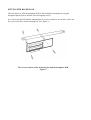
FITTING THE UPGRADE
The second floppy disc drive (drive 1) fits alongside the original drive (drive 0) on the disc drive support
bracket, as follows:
1.
Remove the two screws securing the front moulding assembly at each side. Stand the unit on one side and
remove the three screws securing the front moulding assembly to the base metalwork (see Fig. 2).
2.
Stand the unit back on its feet and unplug the LED/speaker connector PL9 from the main board (see Fig. 4).
Grasp the front moulding assembly at each end and use a straight, steady pull to withdraw it from the front of
the unit.
Fig. 2 - Removing the front moulding assembly
3.
Unplug and remove the ribbon-type data cable which connects between connector SK11 on the main printed
circuit board and the connector on the rear of the original disc drive 0. Connect the centre connector on the
new dual drive cable assembly to drive 0 and the end connector to SK11 (see Fig. 3).
4.
The new disc drive comes with a front facia panel attached. This facia is fitted to protect the unit in transit and
is not required when the drive is installed in an Archimedes system. The facia is held in position by two clips,
one on each side of the drive. These may be levered carefully out of position using a small screwdriver and the
facia removed. Take care not to dislodge the drive eject button while removing the facia.
5.
Before fitting the new drive, it must be configured as drive 1. To do this, set the small slide switch on the
side of the drive to position "1" (see Fig. 3).
Fig. 3 - Dual drive data cable details & configuring the new drive as drive 1
2
6.
Assemble the drive to the drive bracket with 4 of the M3 x 6mm screws supplied, using the original drive
0 assembly as a guide to orientation.
7.
Assemble the drive bracket to the disc drive support bracket with 2 of the M3 x 6mm screws supplied.
Fig. 4 - Installing the new Drive 1
8.
Connect the centre connector on the disc drive power cable and the end connector on the disc drive data
cable to the new drive.
9.
Taking the front moulding assembly, locate and remove the two self-tapping screws at each end inside the
main moulding and slide the sub-moulding away from the main moulding (see Fig. 5).
Fig. 5 - Front moulding assembly details
10. The leads from the speaker in the main moulding and the LED in the sub-moulding share the same connector. The
new dual-drive sub-moulding has an LED already fitted to it. You will need to remove the existing leads from
the connector and replace them with those from the new LED, as follows:
3
11. Using a small electrical screwdriver or similar, depress the barbs on the LED wire contacts
in the LED/speaker connector (red and black wires) and withdraw the contacts from the
connector, noting the polarity of the LED wires (see Fig. 6, steps 1 and 2). Place the old
front sub-moulding to one side.
Fig.6 — Removing/inserting LED wires in LED/speaker connector
12. Offer up the new dual drive sub-moulding to the main moulding, passing the LED wires
through the drive 1 aperture. Ensure that the top edge of the sub-moulding fits into the slot
between the rib and the top edge of the main moulding, then secure the sub-moulding using
the two self-tapping screws previously removed.
13. Insert the LED wire contacts into the LED/speaker connector so that the barbs on the
contacts engage in the slots in the connector housing (see Fig. 6, step 3). Observe correct
polarity - make sure that the red and black wires are the correct way round, as shown in
Fig. 6, step 2.
14. Insert a disc into both drives, then offer up the front moulding assembly to the main unit,
ensuring that the LED/speaker cables pass over the top of the new drive 1. The discs will aid
alignment of the disc eject buttons in the apertures in the front moulding.
15. Insert the front moulding assembly fixing screws and fully tighten them. Check that both
drives will accept and reject discs, that the eject buttons do not bind on the moulding and
that an inserted disc clears the front moulding.
16. Provided that its position has not been disturbed, the original drive 0 should align correctly;
if necessary, loosen the new drive 1 bracket fixing screws and adjust carefully for correct
alignment. Tighten both disc drive 1 bracket fixing screws.
17. Plug the LED/speaker connector to PL9 on the main board, ensuring that the locking ears on
the connector locate either side of the locking tab on the board-mounted connector (see Fig.
6, step 4).
18. Visually check that all is well, then refit the top cover and tighten all fixing screws.
19. Carefully fix the appropriate model label to the new front sub-moulding.
20. Reconnect the keyboard, monitor and peripherals to the computer unit. Reconnect the
system to the mains supply and switch on. QUIT the desktop (if necessary), then enter:
*CONFIGURE FLOPPIES 2
Refer to the User Guide for further guidance.
Copyright Acorn Computers Ltd
Published by Acorn Computers Ltd
June 1988
Part number 0476,062, Issue 1
4
High Performance Computer Systems
Hard Disc Drive Upgrade Kit
Fitting Instructions
Copyright Acorn Computers Limited 1987.
Neither the whole or any part of the information contained in, or the product described in, this manual may be adapted or reproduced in
any material form except with the prior approval of Acorn Computers Limited (Acorn Computers).
This manual is for the sole use of Acorn Computers' authorised dealers and must only be used by them in connection with the
product described within.
First Published 1987
Published by Acorn Computers Limited Part No.
0476,245
Issue 2
March 1988
Contents
1. Introduction
2. Upgrade Kit List
3. Fitting the Upgrade
1. Introduction
This document details the installation of a hard disc drive in an Archimedes 305, 310 or 410 computer system. The appropriate kit
includes all the components needed to complete the installation.
2. Upgrade Kit List
Items common to models 305, 310 and 410:
Item Part No.
Description
1
2
3
4
0176,244/T
0277,014
0882,121
0882,142
3.5" Hard Disc Drive
Hard Disc Drive Bracket
Screw, M3 x 6mm Pan Hd. Pozi
Screw, 6-32 UNC x1/: Pozi
Qty
1
1
2
4
Plus For models 305 and 310 only:
5
6
7
8
9
10
11
12
13
14
0176,241/A
0176,242/A
0176,243/A
0276,035
0882,111
0276,036
0176,240
0476,240
0276,070
0276,071
34-way Ribbon Cable Assy. Long
20-way Ribbon Cable Assy. Long
LED Assembly
1
Single Blanking Panel
1
Screw, M2.5 x 6mm
2
'T' piece
1
Hard Disc Podule Assy.
1
Instructions for Use
1
Front Label, 305H
1
Front Label, 310H
1
1
1
OrFor model 410 only:
15
16
17
18
0177,002/A 34-way Ribbon Cable Assy. Short
0177,003/A 20-way Ribbon Cable Assy. Short
0277,070
Front Label, 410H
0277,315
Front Label, 440H
1
1
1
1
HARD DISC UPGRADE ISSUE 2
1
3. Fitting the Upgrade
WARNING
TAKE ALL PRECAUTIONS REGARDING STATIC ELECTRICITY AND EARTHING IN ACCORDANCE
WITH B.S. 5783
1. Disconnect the computer from the mains supply and all peripherals, including the keyboard.
2. Place the unit, with the rear panel facing you, on a worksurface with a clean, soft covering.
3. Remove the top cover as follows (see fig. 1):
FIG. 1 REMOVING TOP COVER
Remove the two screws in the sides of the top cover, immediately behind the front moulding.
Remove the three screws along the top of the rear panel and remove the top cover by sliding it off from the rear of the unit.
Models 305 and 310:
Model 410:
4. Remove the two screws securing the front moulding assembly
at each side. Stand the unit on one side and remove the
three screws
securing the front moulding assembly to the base metalwork (
see fig. 2).
4. The hard disc drive power cable is tie-wrapped to the side of
the power supply unit. Cut and remove the tie-wrap and
free the cable.
5. Stand the unit back on its feet and unplug the LED/speaker
connector PL9 from the main board (see fig. 4). Grasp the
front moulding assembly at each end and use a straight,
steady pull to withdraw it from the front of the unit.
6. If one is not already fitted, fit a Podule backplane as per the
instructions supplied with the Backplane Upgrade Kit but
ignore the
instruction on page 5 to re-tie any power cables to the PSU.
7. Fit the Hard Disc Podule as per the installation leaflet supplied
with the Podule Kit, ignoring the final section '
REASSEMBLY'.
5. Remove the two backplane mounting screws, unplug the
backplane and rest it on top of the power supply unit.
There is no need to disconnect the power leads.
6. No further mechanical disassembly is required -proceed to step 8.
WARNING
THE HARD DISC DRIVE IS FRAGILE.
DO NOT DROP, JOLT OR SUBJECT IT TO EXCESSIVE VIBRATION.
ALWAYS HANDLE THE DRIVE WITH CARE DURING INSTALLATION.
8. Assemble the hard disc drive to the drive bracket (if this is not already done) with 4 off 6-32 UNC x ¼"
screws supplied. Ensure that the drive is orientated such that the PCB is at the bottom, with the connectors
facing towards the rear of the main unit (see fig. 4).
9. Assemble the drive bracket to the disc drive support 'saddle', with 2 off M3 x 6mm screws supplied.
FIG. 4 HARD DISC DRIVE INSTALLATION
Model 305 and 310:
Model 410:
10. The hard disc drive front panel LED is already
10. Taking the front moulding assembly, locate and
fitted to this model. Proceed to step 16.
remove the two self-tapping screws at each end
inside the main moulding and slide the submoulding away from the main moulding (see fig.
5).
11. Insert the new LED into the 'spare' aperture in the
front sub-moulding, immediately below the
Power On LED. Fix the LED into place using a
small blob of silicone rubber adhesive*.
12. Offer up the sub-moulding, with the new LED
fitted, to the main moulding , passing the LED
wires through the "Drive 1"aperture. Ensure that
the top edge of the the sub-moulding fits into the
slot between the rib and the top edge of the main
moulding, then secure the sub-moulding using the
two self-tapping screws previously removed.
13. Insert a disc into the floppy drive, then offer up the
front moulding assembly to the main unit,
ensuring that the LED/speaker cables pass over
the top of the hard disc drive. The disc will aid
alignment of the floppy disc eject button in the
aperture in the front moulding.
14. Insert the front moulding assembly fixing screws
and fully tighten them. Check that the floppy drive
will accept and reject discs, that the eject button
does not bind on the moulding, and that inserted
discs clear the front moulding.
Provided that its position has not been disturbed,
the floppy drive should align correctly.
Model 305 and 310 cont'd:
15. Connect the hard disc drive LED connector to PL2 (
adjacent to the 64-way connector) on the Hard Disc
Podule, ensuring that the locking ears on the connector
locate either side of the locking tab on the boardmounted connector.
16. Connect the hard disc drive power cable, coming from the PSU, to the power connector on the hard disc drive (see fig.
6). Note: Some hard disc drives may have a power connector on a short flying lead.
17. Connect the 34-way and 20-way ribbon cable assemblies as follows:
Model 305 and 310:
Model 410:
Connect the LONG 34-way cable between PL3 on the
Hard Disc Podule and the 34-way connector on the
rear of the drive; the LONG 20-way cable connects
between PL4 on the Podule and the corresponding
connector on the drive. Route the cables as indicated
below in figure 6.
Connect the SHORT 34-way cable between the 34 way connector on the rear of the hard drive and
SK10 on the main PCB - immediately below it. The
20-way SHORT cable connects in the same way
between SK9 and the corresponding connector on the
drive.
Refit the backplane.
FIG. 6 CONNECTIONS
18. Tighten both hard disc drive bracket fixing screws.
19. Visually check that all is well, then connect the unit to the mains supply and peripherals. Power up and format and
verify the hard disc drive as detailed in the Archimedes Service Manual section "Test Instructions".
20. Disconnect from the mains supply and peripherals, then refit the top cover and tighten all fixing screws.
21. Connect the unit to the mains supply and peripherals. Power up and carry out the "Soak Test" as detailed in the
Archimedes Service Manual section "Test Instructions".
22. Using a scalpel or similar, carefully lift one edge of the model label on the front moulding and remove the label. Affix
the appropriate label in its place.
IMPORTANT
HANDLE THE COMPUTER WITH CARE WHEN THE HARD DISC DRIVE HAS BEEN INSTALLED.
AVOID JOLTING, BANGING OR DROPPING THE UNIT.
4
HARD DISC UPGRADE ISSUE 2
IMPORTANT NOTES:
1. Always park the hard disc drive heads before switching off the unit, as described under Care and Handling of the Hard Disc in the
Archimedes Hard Disc Upgrade instructions for use, part number 0476,240.
2. Ensure that the Archimedes is supplied by, and returned to, the customer in appropriate packing.
3. Rember to return the Archimedes Hard Disc Upgrade instructions for use, part number 0476,240 to the customer with the
upgraded unit.
* Silicone rubber adhesive.
An air-curing one-part silicone rubber adhesive, formulated for use inside electronic equipment, must be used on this equipment.
Suitable types are: Dow Corning Silastic 738 RTV, or
General Electric RTV 162 (available from RS Components)
Before using this adhesive, the manufacturer's data sheet should be consulted in relation to flammability and Health and Safety at
Work notes. Apply only in a well-ventilated area.
ARCHIMEDES HARD DISC UPGRADE
This leaflet provides information on the following:
• installing the upgrade
• using the hard disc
• care and handling of the hard disc
• formattting the hard disc
INSTALLING THE HARD DISC UPGRADE
This hard disc upgrade is intended to be fitted by an Acorn Computers' authorised dealer who will
install, format and test the hard disc unit. In order to use hard discs on the Archimedes 300 series,
it is also necessary to have a Hard Disc Podule installed. This Podule should also be fitted and
tested by an Acorn Computers' authorised dealer. On the Archimedes 400 series, the hard disc
interface circuitry is integral and hence a Hard Disc Podule is not required.
The hard disc upgrade installer should give this leaflet to the user when returning the
upgraded Archimedes.
USING THE HARD DISC
The hard disc installed in the Archimedes gives you access to approximately 20 Mb of filing space
on which to store programs and data. The hard disc is similar in use to a floppy disc except that the
hard disc is permanently 'present' whenever the Archimedes is switched on. The Advanced Disc
Filing System (ADFS) provides facilities for the storage and retrieval of data on both the floppy
disc and hard disc systems installed in the Archimedes.
It may be necessary to change the configuration of the Archimedes to allow access to the hard
disc. The following configuration options may need to be set:
*CONFIGURE HardDiscs 1
causes the machine to expect one hard disc drive on initialisation
*CONFIGURE Drive 4
causes the machine to select drive 4 by default, ie the internal hard disc drive
*CONFIGURE FileSystem 8
or
*CONFIGURE FileSystem ADFS
(for Arthur 1.2 onward)
selects the ADFS to be the default filing system on initialisation
The hard disc is represented on the desktop by a hard disc icon. This icon will appear at the
bottom left of the main desktop screen (next to the floppy disc icon) once the hard disc drive is
fitted and the Archimedes is configured to recognise its presence. The contents of the hard disc
can be viewed and manipulated from the desktop in the same way as for a floppy disc.
Further information on the use of discs and the ADFS can be found in the Welcome Guide, the
ADFSDemo tutorial program in the Welcome Suite and in the User Guide, chapter Filing Systems.
It is possible for hard discs to develop 'defects' during normal use. In this context, a defect is a very
small area of the hard disc surface which is no longer able to store data reliably. This type of defect
is not unusual in hard disc systems and is not normally symptomatic of a failure in the equipment. It
is however important that the ADFS, which organises where data is stored on the disc, is 'told'
where these defects are located in order that it can avoid using these areas for future data storage.
Such defects may be first noticed as 'Disc errors' during normal use of the hard disc.
There is currently only one way of informing the ADFS of the location of these defects and this
requires that the hard disc be reformatted. During the verification process that always follows
reformatting, all disc surfaces are checked for their ability to store data accurately. If any areas are
found to be unreliable, then the locations of these areas are added to a 'map' of defects which is then
stored on the hard disc itself. The ADFS can then consult this 'map' to determine where the defects
on the hard disc are located and hence where not to store data.
It may be necessary therefore to occasionally reformat the hard disc. The method of formatting
the hard disc is different to that for a floppy disc. For details, see the section on Formatting the
hard disc later in this leaflet.
CARE AND HANDLING OF THE HARD DISC
The hard disc unit is a delicate mechanism and requires careful handling. When the hard disc is in
operation, the magnetic read/write heads are located very close to the surfaces of the rotating discs
within the drive unit. As the gap between the read/write heads and the disc surfaces is extremely
small, it is possible that if the Archimedes were jolted, the heads could momentarily touch the disc
surface. This could cause damage to areas of the disc coating where the data is stored or under more
extreme conditions actually damage the heads themselves. It is thus possible that moving the
Archimedes while the hard disc is in operation could cause corruption of data on the disc or even
irrepairable damage to the disc unit.
When the Archimedes is switched off, and particularly when it is to be transported, the hard disc can
be made much more immune to the adverse effects of movement by 'parking' the drive heads.
Parking the drive heads involves moving them to a special area of the disc surface where no data is
stored and where contact between the heads and the stationary surface of the disc will do no harm. In
order to park the drive heads, enter the following commands:
*ADFS [Return]
*BYE [Return]
when the screen prompt reappears, the drive heads will be parked.
If you are in desktop, proceed as follows:
- position the pointer on the hard disc icon which appears at the bottom left of the desktop screen
- click the menu button of the mouse on the hard disc icon and a window containing the word bye
will appear
- position the pointer on the word bye, click select and the drive heads will be parked.
It is good practice to park the drive heads everytime you switch the Archimedes off. If you intend to
move the Archimedes then always transport it in its original packaging and take care not to subject
it to undue bumping and jarring.
With careful handling, the hard disc drive installed in your Archimedes will operate reliably over a
long period. If a failure of some sort should occur, which corrupts the data on the hard disc, it may
be very difficult or even impossible to recover that data. The data on your hard disc may represent
many hours of work and it is vital therefore to keep up-to-date backup copies of important data.
Data may be copied onto floppy discs and these floppy discs then labelled, and stored in a separate
location to your Archimedes. For advice on copying files from the hard disc to floppy discs, see the
Welcome Guide (copying using the desktop) and the User Guide (copying using *COPY).
Alternatively, ask your supplier for information on backup systems which enable you to copy the
entire contents of your hard disc onto a removeable media.
FORMATTING THE HARD DISC
When your Archimedes is returned following the hard disc upgrade, the hard disc should be
formatted and ready for use. The hard disc formatting utility, a BASIC program called WFORM,
will be supplied on the hard disc in the Library directory. It is recommended that you copy
WFORM onto a floppy disc for possible future use.
WARNING: reformatting your hard disc will destroy all data stored on the disc. It is
essential that data which you wish to keep is copied to another media, eg floppy
disc, before the disc is reformatted.
In order to reformat your hard disc, load and run the WFORM program from either the hard disc
or from your backup copy on floppy disc. WFORM can be accessed from either the desktop (
double-click select on WFORM) or from BASIC (CHAIN "WFORM").
WFORM will prompt you for various parameter values as follows:
NOTE: default values for the parameters are given when you run WFORM. These
default values are appropriate for the hard disc supplied as standard by Acorn with
the hard disc upgrade, ie the TANDON model TM362.
Press !I to confirm each value.
1 Format which drive (4 or 5)? 4 [Return]
4 is the value for the internally fitted hard disc drive
5 is the value for an external (second) hard disc drive (if fitted)
2 Sectors per track? 32 [Return]
3 Heads? 4 [Return]
maximum value = 8
4 Cylinders? 615 [Return]
5 Low current cylinder? 1023 [Return]
6 Precompensation cylinder? 1023 [Return]
7 Parking cylinder? 663 [Return]
WFORM will now list the current defects (if any) in the defect list and invites you to change the
list. You may wish to add a new defect because the ADFS has previously returned an error
message, such as:
Disc error 10 at
:4/00831E00
You can use this logical address directly in WFORM by selecting option C.
NOTE:if you are adding more than one defect by logical address, you must add them
in descending order of magnitude. You must also complete the entry of any or all
logical address defects before adding any defect by (physical) cylinder, head and sector
address, ie by option B.
Option B is normally only used to establish an initial defect list on a brand new, previously
unformatted disc. It is also necessary to use option B to re-establish the defect list in the unlikely
event that it has been corrupted, eg due to a power failure during a previous format operation.
Under these circumstances, it would be necessary to remove the top cover of the Archimedes to
gain access to the written defect list stuck to the body of the hard disc drive. The defect information
can then be typed into WFORM via option B. (See the Welcome Guide section How to change the
internal batteries for information on how to remove the top cover of the Archimedes). Always
disconnect the Archimedes from the mains by unplugging the power supply cable, before removing
the top cover.
Select option A when the changes to the defect list are complete. Confirm
your intention to format the disc by typing Y [Return] when prompted.
WFORM will now format and verify the hard disc. If the verification process detects any additional
defects, you can simply add them to the defect list by confirming with Y [Return] when prompted.
WFORM will then repeat the formatting and verification process in order to include the new defects.
The formatting process will now be complete.
©Acorn Computers Limited
Published by Acorn Computers
Limited November 1987
Part number 0476,240 Issue 1
MIDI MODULE INSTALLATION LEAFLET
FOR USE WITH ARCHIMEDES HIGH PERFORMANCE COMPUTER SYSTEMS
The MIDI Module is an upgrade to the I/O Podule which must also be installed in your Archimedes for MIDI to
function. The I/O Podule must be fitted into a backplane, which is available separately. Full instructions for fitting
the backplane and the I/O Podule are supplied with their respective packages.
In order to fit the MIDI Module you will have to remove the lid of the Archimedes unit. The only tools you will
require are a No.1 Posidriv screwdriver and an M2 spanner.
If the I/O Podule and the MIDI upgrade are to be installed at the same time, the alterations to the I/O Podule
should be made before it is installed in the Archimedes. If the Podule has already been fitted it will have to be
removed.
If you do not feel confident about carrying out the installation, you can take the Archimedes and the Module
to your dealer.
DISASSEMBLY
First, switch off the Archimedes at the rear and disconnect it from the main supply by unplugging the power
supply cable. Then, remove any peripherals that are attached and clear the Archimedes completely, ie remove
any monitor from the top of the Archimedes and any other loose items.
Locate the screws holding the top case in place (see Fig. 1 below). First, remove the three screws at the top rear of
the unit. Then remove the single screw on each side of the unit.
Fig. 1: The position of the screws holding the top case.
Once you have removed the three rear screws and the two side screws, slide the lid of the unit to the rear of the
machine and then slide it off. You should remove the lid completely.
To remove the I/O Podule, if it is already fitted, undo the screws at either side of the rear plate and ease the
Podule out of its connector on the backplane, pulling it gently towards you. Make a note of which connector it
was plugged into. Remove the Podule completely from the computer.
PARTS LIST
In the MIDI package you have:
Four ICs (Integrated Circuits) packed on anti-static foam.
Two five pin DIN sockets mounted on a small circuit board with a flying lead and a plug. These are the MIDI
IN and MIDI OUT sockets.
A tiny connector or 'jumper'.
Four nuts, bolts and washers in a plastic bag.
FITTING THE MIDI MODULE
The four integrated circuits are plugged into sockets on the I/O Podule. There are three empty sockets, for which the correct
ICs can be identified by the number of pins. (see Fig. 2). You must take care to put the ICs in the right way round. Pin one is
marked by an indent or a spot at one end of the IC which should line up with the indent drawn on the printed circuit board (
see Fig. 2). Also take care not to bend the pins; if they are splayed out too wide for the socket, press the whole row of pins on
one side VERY GENTLY against a flat surface until they fit.
Fit the ICs by holding the body of the device. In
order to minimise any possible damage to the
IC from static electricity, do not touch the pins.
Fig. 2: I/O Podule showing MIDI Module
The fourth IC replaces the ROM supplied with the I/O Podule. This is the central integrated circuit in the row of three large
ICs (see Fig. 2). You must remove this IC and replace it with the IC supplied with the MIDI Module. Take care not to get them
mixed up. You will have one IC left over when you have finished.
The jumper must be inserted over the two pins next to the word MIDI on the Podule circuit board (see Fig. 2).
Next, the MIDI IN and MIDI OUT sockets are bolted into place on the rear panel of the Podule. First, remove the two rubber
bungs by pushing them through from the circuit board side. The termination of the flying lead goes behind the IN lettering on
the rear plate of the Podule (see Figs 2 and 3). Take care to get these sockets the right way up. Bolt the sockets in position
using the Posidriv screwdriver, preventing the nuts from turning with your fingers or an M2 spanner.
Fig. 3: Alignment of MIDI IN and MIDI OUT sockets
Plug the connector on the other end of the lead into the pins on the right hand side of the circuit board (when you are
looking from the rear, see Fig. 2). This will only go in one way round, don't force it.
REASSEMBLY
You can now fit the I/O podule into the Archimedes according to its fitting instructions.
If you had to remove the Podule from the computer, support the backplane with one hand and push the connector on the Podule
into the socket on the backplane from which you removed it. The connector should be securely seated, that is the rear plate of
the Podule should be flush with the Archimedes case. It is important that you offer the Podule up to the backplane at right
angles to it and that you align the connectors, otherwise you may bend the pins or break or disconnect the backplane itself. It
does not require great force to install the Podule correctly. If the Podule will not seat easily, remove the Podule and start again.
When the Podule is positioned correctly, secure the Podule to the back of the Archimedes case by inserting a screw
at each end of the Podule rear panel.
Once the Podule has been replaced, slide the top case of the Archimedes unit on from the rear, making sure that it is
correctly located in its slots. These slots are positioned one on each side of the lower case.
Replace the two screws that you removed from the front sides of the Archimedes case and tighten them up (see Fig. 1).
Replace the screws at the rear and sides of the unit and tighten them up, (see Fig. 1).
Copyright Acorn Computers Ltd Published
by Acorn Computers Ltd March 1988
Part number 0476,211, Issue 2
ARCHIMEDES ARTHUR ROM FITTING INSTRUCTIONS
This leaflet tells you how to upgrade your Archimedes 300 series to version 1.2 of the Arthur
operating system. It is not difficult to carry out the upgrade. All you need to do is to:
•
•
•
Remove the top cover of your Archimedes
Remove the system ROMs (four integrated circuits)
Carefully insert the four new ones.
The only tools you will need for this are a medium Pozidriv screwdriver and a small flat-bladed
screwdriver or IC extraction tool. You will, however, need to take care to protect the ROMs
from static electricity as this can seriously damage them. However, if you are unhappy about
upgrading your Archimedes yourself then your Acorn supplier will be able to do it for you.
ATTENTION! Arthur 0.2 owners - please insert your old 0.2 ROMs into the protective foam
which carried your new 1.2 ROM set, and return the 0.2 ROMs to Acorn using the envelope
and reply paid label provided in this pack. This request does not apply to Arthur 0.3 owners.
REMOVING THE TOP COVER FROM THE COMPUTER
1
Switch off your Archimedes and disconnect the unit from the mains by unplugging the
power supply cable.
2
Unplug any peripherals that are attached and remove any monitor or other loose items
standing on the top of the case.
3
Locate the screws holding the top cover in place. (See figure 1.)
4
Remove the three screws at the top rear of the unit and the single screws on each side of the
unit.
5
Slide the top cover to the rear of the machine and then slide it off. You should remove the
cover completely and set it carefully to one side.
The position of the screws holding the top cover
Figure 1
LOCATING THE. SOCKETS ON THE BOARD
Position the machine so that you are facing the front. The sockets will then be located halfway along the right-hand
side of the main printed circuit board. They are labelled: IC24, IC25, IC26 and IC27. (See figure 2.)
ROM 1 is in socket IC24
ROM 2 is in socket IC25
ROM 3 is in socket IC26
ROM 4 is in socket IC27
The position of the four ROM sockets
Figure 2
Note: If you have any Podules installed you will need to remove them in order to gain access to the ROM
sockets.
REMOVING THE OLD ICs
You must remove the existing ICs in sockets IC24, IC25, IC26 and IC27. To do this, take an IC extraction tool or
a flat-bladed screwdriver and gently prise up each end of the IC, a bit at a time.
It is important that you remove the ICs extremely gently otherwise you may bend the pins or damage the sockets. If
you are using a screwdriver, be careful not to catch the ribs of the sockets.
IDENTIFYING THE ICs
The upgrade kit consists of four ROMs. The way in which the ICs are labelled and their appearance depends on the
manufacturer. Before inserting the ICs it is important to clearly identify the type of ICs you are supplied with.
Using the table below, identify which IC is which by examining the markings on
them. ROM
Markings
1
2
3
4
0277,022
027,023
0277,024
0277,025
or
Markings
or
MB831000-20P-700
MB831000-20P-701
MB831000-20P-702
MB831000-20P-703
Markings *
1
2
3
4
*Note: The ROM set numbered 1,2,3 and 4 although labelled Arthur 1.1 is in fact Arthur 1.2.
You may find it easier when you come to install the ICs if you make a note of which IC is ROM
1, ROM 2 and so on.
The ICs will be one of two types. These either have a distinctive semi-circular notch at one end of
the IC or a long groove down one side.
INSERTING THE ICs
You are now ready to insert the ICs. When you handle the ICs, it is very important that you
avoid touching the pins and that you protect the ICs from static electricity.
1
2
Remove the ICs from their packaging, holding the IC between finger and thumb.
Check that all the pins on the IC are straight. If they appear crooked or splayed, you will need
to realign them. To do this, hold the IC sideways-on and press it gently against a firm flat
surface.
3
Repeat for the other row of pins as necessary.
4
Identify socket IC24.
5
Take the IC which you have already identified as ROM 1.
6 The new ICs each have only 28 pins so four of the pin positions in each of the 32 pin sockets will
be unused. Position the end of the IC with the semi-circular notch towards the notched end of
the socket. If you have grooved ICs you should position the IC so that the groove is on the lefthand side of the IC. In either case, the four free positions should be left at the notched end of
the
socket. (See figure 3.)
A 28 pin IC in a 32 pin socket
Figure 3
7
Line up all the pins over socket IC24. Ensure that the notch on the IC points towards the notched end of
the socket (or that the groove is on the left-hand side of the IC). Also, ensure that you have left four
free pin positions at the notched end of the socket.
8
When you are sure that the IC is the correct way round, apply firm pressure to the IC until you feel it
click home, but do not force it. When the IC is in place it may appear to be slightly raised.
9
Check that all the pins have entered the socket and that none are bent out or caught underneath.
10
Insert the remaining ICs. Ensure that the IC which you have identified as ROM 2 is inserted into
socket IC25, ROM 3 into socket IC26 and ROM 4 into socket IC27.
REASSEMBLING THE ARCHIMEDES
Now reassemble the Archimedes:
1
If you have removed any Podules, re-install them in accordance with the supplier's instructions.
2
Slide the top cover of the Archimedes unit on from the rear, making sure that it is correctly
located in its slots. These slots are positioned one on each side of the lower case.
3
Replace the screws at the rear and side of the unit and tighten them up. (See figure 1.)
4
Connect up the monitor and keyboard etc and then plug in the mains supply. The
installation is now complete.
In the Desktop, use the mouse (as described in your new Welcome Guide) to select operation.
Note: To go straight to BASIC (rather than the Desktop) set the configuration to LANGUAGE 4.
©Acorn Computers Ltd, 1988
Published by Acorn Computers Ltd
Part number 0476,350
Issue 2
Archimedes 300 series
Service Manual
5. Connectors, interfaces, links and test points 5.1
Archimedes 300 series options and test points
LinkNo.
Status* Function
LK 1
LK 2
NF
NF
Not applicable to A305/310
Selects ROM size for ICs 24 to 27 in combination with LK6. Tracked in position b = 27512
EPROM, see also LK 12 and silk screen table.
LK 3
LK 4
LK 5
LK6
NF
NF
NF
NF
Not applicable to A305/310
Not applicable to A305/310
Not applicable to A305/310
See LK 2
LK 7
LK 8
LK 9
NF
Can be used to ground RDY signal in floppy disc interface for test purposes.
By fitting both in position 3 to supply PL 4 with power, the disc
drive may be powered via the ribbon cable.
LK 10
NF
LK 11
NF
West selects SK2 pin 4 to be HSYNC.
East selects SK 2 pin 4 to be CSYNC (tracked East).
West selects SK2 pin 5 to be VSYNC
East selects SK 2 pin 5 to be a mode control AMODE. PCB is not tracked in either position feature unused.
LK 12
NF
TP 1
TP 2
*NF = Not Fitted
Selects type of 1 Mbit EPROMs/ROMs.
DEFAULT: Links set 1 to 2 and 3 to 4 for EPROMS up to 0.5 Mbit, 1 Mbit
ROMs and 1 Mbit ROM-type EPROMS, eg 27C301. Links set 1 to 3 and 2 to 4,
JEDEC 1 Mbit EPROMS, eg 27C101.
Access to real time clock oscillator
Indicates system access to disc drive.
5.2 Plugs and sockets
PL 1
Serial line
PL 2
Auxiliary audio connector. 10 way 2 row 0.1" pitch
For pin out see silk screen on PCB.
1. Unfiltered left channel output
2. 0V
3. Filtered left channel output
4. 0 V
5. Auxiliary input (feed to internal amplifier and speaker)
6. 0 V
7. Filtered right channel output
8. 0V
9. Unfiltered right channel output
10. 0 V
PL 3a
Internal clock selection. 4 way 2 row 0.1" pitch.
For pinout see silk screen on PCB; shunts fitted 1 to 2, 3 to 4.
1. CKSYS 24 MHz system clock.
2. Feed to VIDC clock
3. Sync signal
4. 0 V
19
ServiceManual
PL 3b
PL 4
Archimedes 300 series
Internal Video 10 way 2 row 0.1" pitch - NF
5 VEDO (inverse of red data bit 0)
6 VED1
(inverse of red data bit 1)
7 VED2 (inverse of red data bit 2)
8 VED3 (inverse of red data bit 3)
9 SUP
(supremacy output control for external video mixing)
10 HI (horizontal interlace marker)
11 HS(horizontal sync)
12 VS (vertical sync)
Floppy disc power connector - NF
Used in conjunction with LK8 and LK9 to power floppy drive via ribbon cable.
PL 5
Power supply connector +12 V
PL 6
Power supply connector 0 V
PL 7
Power supply connector +5 V
PL 8
Power supply connector -5 V
PL 9
Front panel connector, pins 1 to 4 fitted only
1 Speaker connection
2 0V
3 Power on LED connection
4 0V
PL 10
Auxiliary I/O connector - NF
1 0V
2 Aux 2
3 Aux 1
4 C4 Bidirectional IO line
5 NVM alarm signal
PL 11
Battery connection
PL 12
Fan connection
Archimedes 300 series
Service Manual
ANALOGUE RGB
The red green and blue signals are analogue outputs each designed to drive a 75 ohm terminated line.
Composite sync is also available on the H/CSYNC output. This pin can be link selected to carry the Horizontial sync. The
VSYNC/MODE output is normally unconnected and may be link selected to carry Vertical sync. so long as VIDC is
reprogrammed. To maintain high picture quality each signal lead should be an individually screened co-axial cable of 75 ohms
characteristic impedance.
1
2
3
4
5
6
7
8
9
RED
GREEN
BLUE
CSYNC
n/c
0V
0V
0V
0V
Red, Blue and Green into 75 ohms
0
volts
0.7 volts
Minimum Level (Black)
Maximum Level (White)
H/Csync or Vsync/Mode into 75 ohms
<0.2
>0.3
volts
volts
Sync LOW
Sync HIGH
H/Csync or Vsync/Mode unterminated
<0.2
>2.4
volts
volts
Sync LOW
Sync HIGH
MONO VIDEO
The monochrome video is available on a Phono Socket. This is a mix of the Red, Green and Blue signals with a Sync pulse:
Socket viewed from mating side
Service Manual
Archimedes 300 series
PARALLEL PRINTER
1
2
3
4
5
6
7
8
9
10
11
12
25
STB
DO
D1
D2
D3
D4
D5
D6
D7
ACK
BSY
n/c
0V
13
14
15
16
17
18
19
20
21
22
23
24
n/c
n/c
n/c
n/c
0V
0V
0V
0V
0V
0V
0V
0V
Vol
Voh
= 0.5 volts at 24 mA
= 2.4 volts at 24 mA
ACK and BSY
Vol
Voh
= 0.8 volts
= 2.4 volts
ECONET
This socket provides the standard Econet interface.
1
2
3
4
Data
0v
Clock
Data
+
5
Clock
+
-
Sockets viewed from mating side
22
Archimedes 300 series
Service Manual
KEYBOARD CONNECTOR
Signal name
5 volts
0 volts
Serial Data out(to K'board)
Serial Data in (from K'board)
Reset
-Not connected-
Pin number
4
3
6
5
1
2
MOUSE CONNECTOR
Pin function
5 v supply for Mouse
0v return for Mouse
Switch 1
Switch 2
Switch 3
X Reference
X Direction
Y Reference
Y Direction
Pin number
6
4
2
3
8
1
5
7
9
Movement signals are T.T.L. level with a fan out of 1 LS load.
V ol = 0 . 5 volts at Tout of 0.4mA
Voh = 2.4 volts at Tout of -0.1mA
Rise and fall time 20 maximum, Vol to Voh or Voh to Vol. Each
mouse switch operates with a contact closure to 0 V. The switch
debounce period is 20 ms minimum.
SERIAL PORT
1
2
3
4
5
6
7
8
9
DCD
RxD
TxD
DTR
0 Volts
DSR
RTS
CIS
RI
See also the Serial Port Application Note in the Appendix.
Sockets viewed from mating side
23
Service Manual
Archimedes 300 series
HEADPHONES
The headphone socket is designed to drive 1 V maximum into a 32 ohm personal stereo headphone.
INTERNAL PLUGS AND
SOCKETS Floppy disc drive
connector
This socket is used to connect to the floppy disc drive. Power may be supplied via this cable or
separately. See LK8 and LK9.
Pin
1
2
3
4
5
6
7
8
9
10
11
12
13
14
15
16
Function
disc eject
n/c
5V or V
in use
5V or V
SEL 3
5V or V
index
5V or V
SEL 0
5V or V
SEL 1
V
SEL 2
0V
Motor On
Pin
Function
18
19
20
21
22
23
24
25
26
27
28
29
30
31
32
33
DIR
V
STEP
0V
Write Data
0V
Write Gate
V
Track 00
V
Write Prot
12V or OV
Read Data
12V or OV
Side Sel
12V or V
Archimedes 300 series
Service Manual
6. Fault-finding information
The purpose of this fault-finding information is to enable the engineer to trace faults to module level, the modules being defined
as the:
Main PCB
PSU
Floppy disc drive(s)
Podule(s), as fitted
Podule backplane
Keyboard assembly
Mouse
Monitor
It is important to determine as closely as possible the nature and location of the fault to ensure that only faulty modules are
replaced.
Basic test equipment required:
100 MHz oscilloscope DC
Voltmeter
Continuity tester
plus additional items according to the test routine.
In addition, reference should be made to the circuit diagram in Appendix 7.11 and PCB test point and layout diagrams in
Appendices 7.8 and 7.9.
It is advisable to substitute known good units/modules in order to isolate faults before carrying out detailed tests.
In all instances, follow through the checks until the fault is located and identified, then change the appropriate module. For
information on module replacement procedures, etc., see the Acorn Service and Support Strategy document.
IMPORTANT NOTE
WHEN REFITTING OR FITTING A REPLACEMENT ASSEMBLY, CHECKS SHOULD BE
MADE FOR EARTH CONTINUITY BETWEEN THE EARTH PIN OF THE MAINS PLUG
AND THE FOLLOWING:
THE BASE METALWORK
THE REAR PANELS (INCLUDING BLANKING PANELS)
THE TOP COVER
USE AN EARTH CONTINUITY TESTER SET TO 25 AMPS.
6.1 Basic checks
6.1.1 FIRST, CHECK THE OBVIOUS:
With both the monitor and the computer switched on, check for POWER ON indications (computer and monitor ON LEDs). If
neither have power, check the main fuse in the wall plug.
If the computer is powered but not the monitor, check for power on the AC outlet socket at the rear of the computer main unit by
plugging in a known good monitor. Should this also fail, replace the computer power supply.
If the monitor is powered but not the computer, an internal power supply fuse may have blown. Replace the PSU.
If both have power, check by substitution that the monitor and the interconnection cable are serviceable. Check for the correct
power supply output voltages on the main PCB:
PL5 = +12 V; PL6 = 0 V; PL7 = 5 V and PL8 =-5 V
25
Service Manual
Archimedes 300 series
If the power supply is emitting a clicking sound, this indicates either a short between two of its outputs or a faulty power supply.
Make sure all of the ROMs are inserted correctly and that the relevant links (LK2, LK6 and LK12) are correct for the type of
ROMs used. The options and settings of these links are detailed in section 5, "Connectors, interfaces, links and test points".
The keyboard CAPS LOCK light should toggle on and off when pressed and assuming a disc is present, the disc drive light will
glow after a *CAT command. If so, this indicates that the system is alive and that the failure is confined to the video circuitry.
Try an 'R' power up (see Appendix 7.4.1). If this has no effect, change the main PCB.
If there is no response, substitute a known good keyboard and repeat the check. If there is still no response, there is a system
failure - change the main PCB. If the substitute keyboard restores normal working, change the original keyboard PCB.
6.1.2 FLOWCHARTS
The following flow charts will be useful aids to basic checks:
NO DISPLAY
Archimedes 300 series
NO SOUND
*TEST PROGRAM:
10 REM > Check all channels
20 VOICES 8
30 FOR channel=1 TO 8
90 OSCLI ("Channelvoice "+STR$ (channel) +" "+STR$ (2) )
50 NEXT
60 FOR channel = 1 to 8
70 SOUND channel, -15, 100,29
80 PRINTchannel
90 k=GET
100 NEXT
RUN PROGRAM.
PRESS A KEY AND REPEAT 8 TIMES.
PRINTS CHANNEL NUMBER ON SCREEN AND
PLAYS VOICE 2 FOR EACH CHANNEL.
Service Manual
Service Manual
Archimedes 300 series
6.2 Run main PCB Functional Test (see Appendix)
The following notes refer to the test procedures on the PCB functional test disc, as detailed in section 7.4 "Archimedes Test
Instructions", and the action which should be taken as the result of a test failure.
Type/Model:
Memory area fault If model 305, change the main PCB
If model 310 with 0.5MByte RAM Upgrade, replace upgrade and retest. If it still fails test, change the
main PCB, using a replacement 310 board, or transferring the original RAM upgrade to the new board. If
model 310 with factory-fitted RAM, replace the main PCB.
Memory:
Repair as above.
Batterybacked RAM:
Check batteries, battery holders and connections. Re-run the test.
If test still fails, replace the main PCB.
Loudspeaker:
If no sound, check speaker connections. Substitute a known good speaker and re-test. If OK, replace
speaker. If test still fails, replace main PCB.
Headphones:
If no sound or poor/faulty sound on known good headphones, replace the main PCB.
Monitor Screen:
If display rolls or is unstable, perform 'R' power-on until correct default value obtained. If no
improvement, check/change the monitor cable. If still no improvement, change the main PCB.
If the display breaks up around its edges and spurious characters appear suspect the system oscillator.
Change the main PCB.
Colours incorrect
or missing:
Floppy Disc:
With a full white screen, VIDC IC 17 pins 39, 40 and 41 should all have the same signal on them.
If not, change the main PCB.
If test fails, check that the configuration for 'STEP' and 'FLOPPIES' is correct. Check the disc drive ID
switch is set to the correct position - normally '0' for single (or first) floppy drive, '1' for second floppy
drive.
Swap the cable and drive for known good examples. Check power to to drive. If fault persists, change
the main PCB.
Serial port:
If test fails, after you have ensured that the loopback plug is functional on another unit, change the
main PCB. If a fault is reported but the test is passed, see the Serial Port Application Note in the
Appendix for possible explanations.
Printer:
If the test fails with a known good printer and cable connected, check the configuration settings for '
PRINTER' and 'IGNORE' are correct. If fault still persists, change the main PCB.
6.3 Hard Disc
Carry out the hard disc and Podule interface tests. IMPORTANT
THE HARD DISC AND PODULE INTERFACE TESTS WILL DESTROY ANY DATA ALREADY
STORED ON THE DISC.
Check that the configuration settings are correct.
If drive is faulty, replace it using the Hard Disc Upgrade instructions as a guide. Replace a faulty
Podule using the Podule installation leaflet as a guide.
28
Archimedes 300 series
Service Manual
6.4 Podules
Run basic checks first - see section 6.1.
Run the relevant Podule test; if it fails, substitute a known good Podule. If the test still fails, replace the main PCB.
6.5 Keyboard
Make sure that the configuration items 'DELAY' and 'REPEAT' are set to sensible values - eg DELAY 32, REPEAT 4.
Perform the basic checks first - see section 6.1. Run the keyboard functional test. If the keyboard
PCB is replaced, re-run the keyboard functional test.
6.6 Audio
Run the main PCB Functional test - see Appendix 7.4 for details.
Service Manual
Archimedes 300 series
7. Appendices
7.1 Modules/Dealer Serviceable Parts ...........................................................................................31
7.2 Production and Field Changes.................................................................................................. 3 2
7.3 Archimedes Serial Port - Application Note.............................................................................. 3 5
7.4 Test Instructions
7.5 Sample Service Report
7.6 Function Map............................................................................................................................ 3 7
7.7 Plugs and Sockets..................................................................................................................... 3 9
7.8 Links and Test Points................................................................................................................41
7.9 Main PCB Component Layout................................................................................................. 4 3
7.1 OFinal Assembly Drawing....................................................................................................... 4 5
7.11 Lower Case Assembly Drawing............................................................................................. 4 7
7.1 2Circuit Diagram...................................................................................................................... 4 9
Archimedes 300 series
Service Manual
7.1 Modules/Dealer Serviceable Parts
The main PCB currently supplied as a replacement is the model 305 board with 0.5 Mbyte RAM and
without ROMs fitted.
See the Acorn Service and Support Strategy document for details of replacement PCB availability.
The following is a list of modules and dealer-serviceable parts available for module-level repairs:
Part Number
Description
TBA
0704,105
0176,100
0176,002
0176,003
0176,004
0176,005
0176,006
0376,340
0999,438
0870,353
0890,009
0276,002
0276,003
0276,004
0276,006
0276,007
0276,015
0276,017
0276,029
0276,030
0276,019
0277,220
0476,000
0476,002
0276,017
0276,318
Keyboard
Arthur ROM set (4 x ROMs)
4464 RAM available as 0.5Mbyte upgrade kit (AKA 51)
Keyboard Assembly
Power Supply Unit
Mouse
Floppy Disc Drive
Single Floppy Disc Drive Data Cable
Speaker/LED assembly
PCB A Spares kit (305 PCB only with 0.5Mbyte RAM, no ROMs)
Keyboard Curly Cable
Power Lead (white, 2m long, 13A)
Rubber Feet
}
) Main Unit Moulding Set
)
Top Metalwork
Bottom Metalwork
Front Label
}
Base Label
}305 Label Set
)
)Poly Packing
Cardboard Carton
Welcome Disc
Welcome Guide
User Guide
Base Label (common 305/310)
}
Front Label
) 310 Label Set
0276,101
0276,102
0276,103
0276,105
0276,106
0276,107
0276,104
0890,011
0276,108
TBA
Top Case
Bottom Case
Leg Moulding (set of 2)
Friction Pads
Name Label
LED Label
Window Moulding (function key strip)
Rubber Feet
Reset Keytop Moulding
Keytop Set
}
}Keyboard Case Set
)
}Keyboard Label Set
31
Service Manual
Archimedes 300 series
7.2 Production and Field Changes
The following information gives changes and deviations made to the Archimedes 300 series during
production and is the latest available when this manual was compiled. It will be updated accordingly as
information becomes available.
Main PCB
MONO VIDEO OUTPUT
Some issue 2 boards may have a mono video output fault. If other checks do not reveal the cause, check for
the presence of insulation tape beneath the RGB video connector mounting bracket. If no tape is fitted,
suspect a short circuit on the mono video track; check for a short circuit to earth (NOT Ov) and, if found,
replace the main PCB.
SOUND OUTPUT FAILURE
Insertion of the jack plug into the audio output socket SKT1 causes a temporary short of both audio
output devices Q9 and Q11 to OV. If the audio output is not working, check for BC239s fitted at Q9 and
Q11. If so, change the board. On later boards, Q9 and Q11 are 2N3904s - these will tolerate the momentary short and are therefore unlikely to be the cause of audio output failure. Note that the two types are
fitted differently to the board - see Fig. 6.
FIG. 6 VIEW OF ALTERNATIVE TYPES Q9, Q11 AS SEEN FROM ABOVE.
SERIAL PORT
On issue 1 boards only, two wire links are fitted around ICs 7 and 15, as follows:
IC7 pin 3 and IC15 pin 10 are not inserted into the pcb and are connected by a wire link across the top
side of the PCB.
The second wire link is fitted between IC7 pins 1 and 4 on the underside of the PCB.
EXCESSIVE BACKGROUND NOISE ON SPEAKER (Acorn FCO E008 refers)
Later boards have a modification to reduce hum from the internal loudspeaker caused by acoustic pickup.
The modification comprises a 10 V or higher 100µF capacitor fitted between pins 7 (+ve) and 4 (-ye) of
IC68. The capacitor should be fitted as close as possible to the IC and should be secured to the PCB using
glue or hot wax. RS part number 104-449 or 103-957 are suitable capacitors.
Machines in the original serial number range 27-AKB10-1000001 to 27-AKB10-1001277 and 27AKB15- 1000001 to 27-AKB15-1001752 were not fitted with this modification in production. However,
machines outside this range may, on subsequent repair, have been fitted with circuit boards which are
not modified.
Note that the noise on earlier computers when BREAK or ESCAPE is pressed is due to a software
problem with earlier versions of Arthur, and will be cured when Arthur 1.20 is fitted.
Archimedes 300 series
Service Manual
RGB OUTPUT VOLTAGE LEVELS (ACORN FCO E009 REFERS)
The RGB output voltage levels have been raised in production to improve compatibility with certain
types of multi-sync monitors. In addition, sync on green is no longer provided. Where problems are
experienced with RGB levels being too low for a given monitor, change the values of 0.25W 1% resistors
R20, R41 and R59 to 43.2Ohn and remove R39. If 43.2Ohm resistors are not available, 43Ohn 1% 0.
25W, Farnell part number MRS2543R or RS part number 148-168 may be used as an alternative.
Note: There are problems inherent with removing components from four-layer boards. Components
should only be desoldered from the board using vacuum desoldering equipment. An acceptable
alternative would be to cut the wires to the components concerned, leaving enough of the wire on the
board to allow the new resistor wires to be soldered to them. The new wires should be cropped close to
the resistor, but allowing the new solder joint to be effected. On removing R39, which is no longer
required, crop the wires back to the board.
VIDEO NOISE (ACORN FCO E011 REFERS)
Breakthrough of system noise occurs onto the screen. This shows as rippling on screen and is particularly
noticeable with colour monitors. This seems to be particularly prevalent when running 'Arcwriter'.
If this occurs, solder a 1N4148 diode in parallel with R67 (adjacent to VIDC IC17) with the cathode (dark
stripe) at the end nearest Q13. Remove the decoupling capacitor 'A' nearest to IC17, between it and Q12
either by using desoldering equipment or by cutting the capacitor out, leaving wires long enough to attach
a new component. Replace this capacitor with a 22µF 6.3 V or higher axial lead electrolytic capacitor, eg
Farnell part number 030 34229. Observe polarity - positive end furthest away from Q12.
PCB MOUNTING
There have been several methods employed of mounting the main PCB in the case.
i.
8 support pillars fixed to the case. The board rests on these pillars, and is attached to the rear panel.
ii.
Later boards are supported by finger grips in the front moulding, with 3 support pillars under the
PCB, plus the rear panel. On some units, the 3 support pillars are attached to the board.
iii. The PCB is supported by finger grips in the front moulding and attached to the rear panel. Two PCB
slide guides support the board along each side of the case, plus one central support pillar
attached to the board.
In all instances, exercise extreme care when removing the board from the case, so as not to snag supports
or damage the board.
Link 12
Link 12 enables selection of ROM device types. The default setting is for EPROMs up to 0.5Mbit, 1Mbit
ROMs and 1Mbit non-JEDEC EPROMs. Changing link 12 would allow the use of 1Mbit JEDEC
EPROMs.
Issue 1 boards do not have the link fitted.
Issue 2 boards have a link consisting of either four pads or pins and shunts. The tracking is as for an issue
1 board. If the shunts are reversed, this may stop the machine functioning. Tracks need to be cut to
change the link.
Phono socket (mono video)
Issue 1 boards have a mono video phono connector fitted to the PCB rear panel, with flying leads from
the PCB.
Issue 2 boards have a board-mounted socket. As the back panel is changed with the board, this
difference does not cause a problem with board change.
Battery holder
The battery holder is riveted to the base metalwork. If the battery holder is replaced, care must be taken
to ensure that the fixing rivets are fitted to the two holes originally used. Only two of the four possible
holes hold the battery holder assembly rigid.
33
Service Manual
Archimedes 300 series
Saddle
The disc drive support 'saddle' is fixed to the base metalwork by either screws or, on later units, rivets. All replacement base
metalwork will have a saddle riveted in position.
PSU
Power Supply Units manufactured by Sanken have a screw head in the case which may foul the rear panel busbar. If fitting a
Sanken PSU as a replacement, it may be necesssary to modify the busbar by filing a piece out of it to clear the screwhead.
Archimedes 300 series
Service Manual
7.3 Archimedes Serial Port - Application Note
The Serial Port electrical interface is based on the American EIA (Electronic Industries Association) standard RS423. The
interface functionality is based on the RS232 standard.
The RS232 standard defines the interface between Data Terminal Equipment (DTE) and Data Communication Equipment (DCE)
employing serial binary data. In the case of an Archimedes system using a modem, the computer is the DTE and the modem
connected to the Serial Port is the DCE. When a serial printer is used, or another computer is connected to the Archimedes
computer, both devices may appear as DTEs and the interconnections will be different.
The RS423 standard defines the electrical characteristics of an unbalanced digital interface circuit such as the Archimedes Serial
Port.
The RS232 standard is very broad-based in its scope, and defines the use of a 25-way connector with many connections between
the DTE and DCE. In practice, many equipment manufacturers have found the only a small sub-set of these connections is
necessary and connectors with far fewer pins have been used. Unfortunately, the selection of the sub-set is often arbitrary and
there may confusion over how to make the best use of the connections provided. Only two wires (plus ground) are actually
needed, theoretically, to make a two-way serial data connection between the DTE and the DCE. The additional connections are
primarily used to carry out "hardware handshaking". The "handshaking" enables the two pieces of equipment to exert some direct
control over each other to allow synchronisation of data flow. This synchronisation is necessary to avoid data loss. Increasingly, "
software handshaking" is used instead of "hardware handshaking". In this case, whilst data is transmitted along one data line, the
other line is used to carry control information that allows the sender and the receiver to synchronise via software control at each
end.
The Archimedes Serial Port uses a 9-way connector (D-type plug) that is similar in function, but is not identical, to the 9-way port
on the IBM PC/AT or derivatives. The same connecting lead can normally be used as that supplied for the PC/AT.
The pin connections for the 9-way connector are as follows:
Pin
Function
Voltage & Logic State
1
DXD
Data Carry Detect
2
3
4
5
6
7
8
9
RXD
Receive Data
TXD
Transmit Data
DTR
Data Terminal Ready
GND Ground Return (OV)
DSR
Data Set Ready
RTS
Request To Send
CTS
Clear To Send
RI
Ringing Indicator
+ve - On (Detected)
+ve - Logic "0"
+ve - Logic "1"
+ve - On (Ready)
+ve - On (Ready)
+ve - On (Send)
+ve - On (Clear)
+ve - On (Ringing)
The Archimedes Serial Port applications include:
Connection to another computer
In this case, both devices behave as DTEs and the RXD and TXD lines need to be transposed between the computers. Software
handshaking will often be used, with some hardware control "loop-back" locally:
Connect pins 1, 4 & 6 (DCD, DTR and DSR) together
Connect pin 2 (RXD) of the DTE (Archimedes) to TXD of the DCE (modem) Connect pin 3 (
TXD) of the DTE (Archimedes) to RXD of the DCE (modem) Connect pin 5 (OV) of the
DTE to OV of the DCE
(us)
Connect pin 7 (CTS) of computer A to pin 8
of computer B Connect pin
8 (RTS) of computer A to pin 7 (CTS) of computer B
Connection to a modem
In this case, the computer is the DTE and the modem is the DCE. The RXD and TXD lines are not transposed and the DCD,
DTR & DSR lines may be brought into use. The TXD, RXD, CTS, DCD, DTR,
Service Manual
Archimedes 300 series
DSR and 0V lnes of one device are connected to the same pins on the other device.
Note: In both of the above arrangements, the CTS line does not behave in quite the same way as for the
existing Master Series or BBC Model B computers. The CTS line on the Archimedes computer, when
disabled, will cause an immediate cessation of data flow. For byte-oriented protocols, this may be
undesirable as the last character may be corrupted. For applications where this is likely to be a problem,
the DSR input should be used instead of CTS (ie the functions should be reversed). The DSR input, when
disabled, allows completion of the current character.
Connection to a serial printer
Both devices will typically be DTEs and some hardware handshaking may be needed. Connections will
be similar to the "computer to computer" method, but will vary between printer types. The printer manual
should be consulted for guidance.
Baud Rate
The serial controller chip within the Archimedes computer provides one internal timer for baud rate
control. If the Receive and Transmit rates are programmed to be the same, then this timer is used for both.
If different baud rates are needed for Transmit and Receive, then the internal timer is allocated to a system
timer. This system timer is not an exact multiple or sub-multiple of the internal timer. The use of different
Receive and Transmit rates is therefore only recommended for lower speed usage, eg 1200/75 Viewdata.
If only Receive is being used, it is important to program Transmit to the same rate, even though it is not
being used. This ensures that Arthur allocates the internal timer to Receive.
Versions of Arthur
Early versions of Arthur, ie those prior to version 1, have a problem which can affect Received data. If it
becomes necessary for Arthur to signal to a sender to stop sending data, due to a full buffer etc., then
Arthur fails to re-enable the sender when the problem clears. A patch is supplied on the Welcome disc for
machines supplied with Arthur version 0.3.
Copies of the RS232 and RS423 standards may be purchased from the BSI in Milton Keynes, UK, or direct
from the EIA in Washington DC, USA. There are related European and International standards as indicated
below:
RS232 Interface between data terminal equipment and data communication equipment
employing serial binary data exchange
RS423 Electrical characteristics of unbalanced voltage digital interface circuits
CCITT V24 Interchange circuits
CCITT V28 Electrical characteristics
ISO 2110 Pin connections for V24 circuits with V28 characteristics
This information is subject to change without notice. No responsibility can be taken for any errors or
omissions. The user or program writer should verify that any application program or connection is
suitable for the intended environment(s).
Archimedes 300 series
7.4 ARCHIMEDES TEST INSTRUCTIONS
Contents
1
General test procedure
2
3
4
5
6
7
8
9
300 series main PCB Functional test
300 and 400 series keyboard Functional test
Dual floppy drive test
Hard disc format and hard disc interface Podule tests
ROM Podule test
I/O Podule and MIDI upgrade test
MIDI Podule test
Backplane test
Note: Please read the following section 'General test procedure' before you carry out any of the tests.
Service Manual
Service Manual
Archimedes 300 series
1. GENERAL TEST PROCEDURE
Contents
1
2
3
4
5
6
7
8
9
Safety
Connecting and disconnecting the power
Validating the test equipment
Before you start
The test disc
Carrying out the tests
Error messages
Performing Soak tests
Repairing faults
1. Safety
Some of these tests require that you remove the top cover of the Archimedes computer. Although the power supply
unit is designed to comply with BS415 Class 2, you must still take care to ensure that no metal objects fall (or are
put) into the power supply unit through the ventilation holes.
2. Connecting and disconnecting the power
•
•
You must CONNECT the power only when you have made all the other connections
You must DISCONNECT the power before removing any other connections.
3. Validating the test equipment
Before carrying out any of the tests in this section, validate the test equipment using a known good part. If the test
equipment fails, you should repair the test equipment and retest on a known good part.
4. Before you start
Before the start of each day or testing session, you must first:
•
•
Adjust the colour monitor to ensure adequate contrast
Inspect all the mechanical parts of the test equipment and replace any parts as necessary.
Also, if required:
•
•
Ensure that the printer has sufficient paper
Connect the printer and monitor to the mains supply. Do NOT turn on.
5. Saving and restoring the CMOS RAM
The tests alter the contents of the battery backed RAM that holds the Archimedes' configuration data. These must
be saved before any of the tests are run, and restored when the last test is over.
1
2
3
Insert the Test disc into the floppy disc drive.
If your screen is showing the desktop environment, use the mouse to click on the 'EXIT' icon,
otherwise, type *GOS.
At the Arthur supervisor prompt (an asterisk) type the following;
DRIVE 0
CMOSLS
Archimedes 300 series
Service Manual
4
5
When prompted, replace the Test disc with an ADFS 800k write enabled disc, the data disc.
Type 'S' to save the contents of the RAM, or 'L' to load a previously saved copy of the RAM.
6
Type the filename to use.
7
8
9
When prompted, replace the Test disc in the drive and press the space bar to continue.
Put the data disc in a safe place. Do NOT use this disc for the later floppy disc test.
Type 'Q' to quit this option. The Dealer Test Menu is displayed; select the 'Quit' option.
5. The Test Disc
The test disc contains various options which are selected from menus e.g:
Dealer Test Menu
1
2
3
4
5
6
A300 Tests
A400 Tests
Podules & Upgrades
Load/Save CMOS RAM
Keyboard Test
Quit
SELECT OPTION :
To select an option, type its number. Some options lead to further menus, other options run tests
immediately.
6. Carrying out the tests
There are two types of tests - subjective and non subjective. The test program passes or fails the
equipment on the non-subjective tests; however, you must judge whether the equipment passes or fails
the subjective tests.
7. Error messages
•
•
If a message is expected and has not appeared within 30 seconds, you must record the fault,
disconnect the machine and repair before retesting
If a test fails, then you should record the fault and attempt to continue with the tests. You should
also note any other failures, but bear in mind the possibility that these failures are caused by the
first recorded failure.
8. Performing Soak tests
At the end of each test, you should carry out a Soak test. To do this, leave the unit under test powered up
for eight hours or alternatively overnight. After carrying out the Soak test, it is advisable to retest the unit.
9. Repairing faults
When repairing the Archimedes 300 series, you should repair the faults in the order in which they
occurred during the test ie repair the first recorded failure FIRST.
For further information on checking for faults and carrying out repairs, refer to the appropriate module
section of this manual.
A list of part numbers for products necessary to make module level repairs may be found in Section 7.1.
Service Manual
Archimedes 300 series
TEST INSTRUCTIONS: 1
ARCHIMEDES 300 SERIES MAIN PCB FUNCTIONAL TEST Contents
1
2
3
4
5
5.1
5.2
5.3
5.4
5.5
5.6
5.7
5.8
5.9
5.10
5.11
6
7
Introduction
Equipment required
Connecting up the equipment
Powering up
300 Series main PCB Functional test
Computer type/model
Memory
Battery-backed RAM
Time
Loudspeaker
Headphones
Standard monitor
Floppy disc drive
RS423 port
Printer
On completing the tests
Disconnecting the equipment
Packing
Note: Please read all the instructions before you start.
1. Introduction
The Archimedes 300 series main PCB Functional test should be carried out after ANY repair to the machine and consists
of the following individual tests:
•
Computer type/model
•
Memory
•
Battery-backed RAM
•
•
Time
Loudspeaker
•
Headphones
•
•
Standard monitor(s)
Floppy disc drive
•
RS423 port
•
Printer.
Archimedes 300 series
Service Manual
2. Equipment required
In order to carry out the tests, you will require the following equipment:
•
Archimedes computer with pcb to be tested
•
Archimedes keyboard
•
3.5 inch Test disc which is write protected
•
•
ADFS 800k formatted, write enabled, 3.5 inch discs
serial port 'loopback' plug
•
Epson FX80 or Olivetti JP101 printer
•
pair of 32Ohm stereo headphones
•
monochrome monitor
•
analogue RGB monitor
The Archimedes computer, keyboard, Test disc, ADFS 800k formatted disc and serial port loopback plug are designed and
specified by Acorn Computers Ltd and may not be changed without written consent from Acorn. All items should be complete
with the correct cables so that you can connect them to the Archimedes computer.
Note: You can replace the specified printers with any other manufacturer's direct functional equivalent (in terms of BOTH
hardware interface and software).
3. Connecting
up the equipment
It is important to connect the equipment to the Archimedes computer in the correct order. Connect the:
•
keyboard to the front panel connector
•
serial port 'loopback' plug to the 'RS423' socket
•
printer to the 'Parallel Printer' port
•
headphones to the 'Headphones 32Ohm' socket
•
•
monochrome monitor to the 'Mono Video' socket
analogue RGB monitor to the 'Analogue RGB' socket
•
monitors to the mains supply
•
Archimedes computer to the mains supply.
4. Powering up
Before beginning the test, ensure that you have saved the CMOS RAM. Then:
1
Turn on all equipment EXCEPT the Archimedes computer.
2
Insert the Test disc into the floppy disc drive.
3
Whilst holding down the 'R' key, turn the computer on. If the 'R' Power-up is successful, a red border appears
momentarily on the screen before the Desktop environment appears. (The Arthur supervisor prompt appears if the
machine has not been upgraded to Arthur 1.2.)
4
If the display is not stable, switch off the computer and repeat the procedure described in step 3.
Normally, you need to execute the 'R' Power-up procedure twice in order to display the correct screen. This is
because the software toggles between two 'SYNC' options.
Service Manual
Archimedes 300 series
5. Running the tests.
To run the test program you should:
1
Hold down Shift
2
Press and release Break .
The 'Dealer Test Menu' is displayed:
Dealer Test Menu
1
2
3
4
5
6
A300 Tests
A400 Tests
Podules & Upgrades
Load/Save CMOS RAM
Keyboard Test
Quit
Select the option 'A300 Tests'. The next menu is displayed:
A300 Test Menu
1
2
3
4
All Tests
All Tests
All Tests
Return to
Except Printer
and Epson Printer
and JP101 Printer
main menu
Select the tests for the printer connected to the Archimedes computer.
Note: If you do not want to test the printer and do not need a print-out of the results, you can select the 'All Tests Except
Printer' option.
5.1 Computer type/model
After loading the test program, the Archimedes computer cycles through a series of tests beginning with the Computer type/model
test. This test is extremely fast and the type and model number of the computer is displayed immediately:
This computer is an
ARCHIMEDES nnn
CHECK FRONT LABELS
THEN PRESS <SPACE> TO CONTINUE
You should:
1
Check that the number displayed on the screen is the same as on the label on the front of the Archimedes
computer.
2
If the number is NOT the same, check inside the machine for the amount of RAM fitted. If the test is giving the
wrong result there is a fault in the memory areas.
3
If the number IS the same, press the Space Bar to continue with the next test.
Archimedes 300 series
Service Manual
5.2 Memory
The Functional test continues by testing the memory. The screen clears and displays the following
messages:
Memory test
Phase one: Incrementing pattern ....
Phase two: Cycling bits ......................
PASSED/FAILED message
A failed message will end the tests. If the test has PASSED, press the Space Bar to continue the test.
5.3 Battery backed RAM
The test continues by testing battery backed RAM. The following message is displayed on the screen:
Battery Backed Ram (BBR) test running.
Reading BBR into main memory.
Checking read/write function of BBR.
Re-loading configuration parameters.
PASSED/FAILED message
PRESS <SPACE> TO CONTINUE
Press the Space Bar to continue the test.
5.4 Time
The Functional test continues by testing the time and date settings. A series of options are displayed on
the screen:
DO YOU WANT TO ?
1. CHECK THE DATE AND TIME
2. SET THE DATE AND TIME
3. CHECK THEN SET THE DATE AND TIME
PRESS 1 OR 2 OR 3
The normal procedure is to select option 1. If you want to reset the time or date you would select 2 or 3.
For example, you can:
1
Type 1 to check the date and time.
2
Check that the time is correct and the seconds are incrementing correctly.
3
To continue with the test, press the Space Bar.
Service Manual
Archimedes 300 series
5.5 Loudspeaker
The Functional test continues by testing the operation of the loudspeaker. A short repeating sequence of
five musical notes is played and the following message is displayed:
LOUDSPEAKER TEST
LISTEN AND CHECK SOUND
THEN PRESS <SPACE> TO CONTINUE
You should:
1
Listen to the sequence of notes.
2
This is a subjective test, so if you detect any deviation, make a note of the fault.
3
To continue with the test, press the Space Bar.
5.6
Headphones
The Functional test continues by testing the 'Headphones 32Ohm' socket. The following message is
displayed as the test proceeds:
HEADPHONE TEST RUNNING
LISTEN AND CHECK SOUND
THEN PRESS <SPACE> TO CONTINUE
The test consists of a repeating sequence of eight musical notes. The first four notes are played on one
headphone and the next four notes on the other headphone.
1
Put on the headphones.
2
3
4
Listen to the sequence of notes.
This is a subjective test, so if you detect any deviation in either headphone, note down the fault.
To continue with the test, press the Space Bar.
5.7 Standard monitor
This test consists of a series of screen displays. You proceed through the test at your own pace.
The first display consists of a series of white lines radiating from the top-left corner. A cursor, in the
shape of a three-coloured acorn, travels across the screen, starting from the bottom left and finishing at
the top right. The features to check are:
•
the accuracy of the lines
•
the movement and integrity of the cursor
•
the transparency of the acorn image as it moves across the lines.
This is a subjective test, so make a note of any faults.
When you have finished looking at the screen display, press the Space Bar to move to the next display.
Archimedes 300 series
Service Manual
The next screen displays consist of four test cards. There is a test card for each of the three colour guns,
and a 'grey scale' to test the three guns. The four test cards are:
•
Red scale
•
Green scale
•
Blue scale
•
Grey scale.
Each test card consists of 16 concentric circles beneath a horizontal band which is divided into 16 sections.
A pale border highlights the leftmost eight sections of the band in order to distinguish the band from the
background. The whole test card is surrounded by a contrasting border.
The purpose of the cards is to display 16 shades with the shade of the border as the middle of the range.
You should observe:
•
the 16 shades displayed
•
the mid-coloured border
•
the quality of the 'grey scale' display
•
the integrity of each test card.
This is a subjective test, so make a note of any faults which you detect and when you are ready to
continue press the Space Bar.
5.8 Floppy disc drive
The Floppy disc drive test consists of two parts. The first part of the test checks the write protect
mechanism. The test disc must be write protected for this test to work. If the Archimedes disc drive
passes the following message is displayed:
Insert Test disc 2 in drive 0
Then press SPACE
Replace the Test disc with an ADFS 800k write enabled disc, the scratch disc. Any data already on this
disc may be destroyed, so it is best to use a blank disc.
The test continues with disc Read, Write and Erase tests. Each test gives a PASSED/FAILED message.
5.9 RS423 port
The RS423 port test is carried out automatically and gives a PASSED/FAILED message.
5.10 Printer
The Printer test sends a test pattern to the printer. The pattern comprises a repeated series of stepped
lines each representing bits 0 to 7. You should look for missing or corrupted pattern. As this is a
subjective test so make a note of any faults that you detect.
Service Manual
Archimedes 300 series
5.11 On completing the tests
On completing the tests the screen displays:
TESTS COMPLETE
and outputs a message to the printer. This indicates that the Archimedes computer has passed all the
non-subjective tests. However, the message Tests Complete should NOT necessarily be interpreted as a
PASS, since you may wish to fail the computer on one of the subjective tests.
If a failure has been found during the non-subjective tests, the screen displays a FAILED message and
lists the failures on the printer, assuming that the printer is functioning and that you did not select the '
All Tests Except Printers' option from the menu.
6. Disconnecting the equipment
1 Switch OFF the power to the Archimedes computer (at the mains switch on the rear of the machine).
2 Switch OFF the power to the rest of the equipment.
It is important to disconnect the equipment from the computer in the correct order, ie disconnect the:
•
•
•
•
•
•
•
•
Archimedes computer from the mains supply
monitor from the mains supply
monochrome monitor from the 'Mono Video' socket OR
analogue RGB monitor from the 'Analogue RGB' socket
headphones from the 'Headphones 32ohms' socket
printer from the Parallel Printer' port
serial port loopback plug from the 'RS423' socket
keyboard from the front panel connector.
7. Packing
Finally repack the Archimedes computer in its box. Note, however, that the packaging used for the
Archimedes 305 and 310 is NOT suitable for an Archimedes computer which has been upgraded with a
hard disc. Do NOT send the hard disc unit through the post or by courier unless you have provided
alternative packaging.
Archimedes 300 series
Service Manual
TEST INSTRUCTIONS: 2
ARCHIMEDES 300 & 400 KEYBOARD FUNCTIONAL TEST
Contents
1
2
3
4
5
5.1
5.2
5.3
5.4
6
7
Introduction
Equipment required
Connecting up the equipment
Powering up
Running the test
Keys stuck
LED
Mouse
Keys
Disconnecting the equipment
Packing
Note: Please read all the instructions before you start.
1. Introduction
This test should be carried out whenever you repair or replace either a 300 or a 400 Series keyboard. The test checks that:
•
the keys are open and functioning
•
the LEDs are functioning
•
the mouse buttons are functioning
2. Equipment required
In order to carry out the tests, you will require the following equipment:
•
Archimedes keyboard to be tested
•
•
Archimedes mouse to be tested
Archimedes computer
•
known good Archimedes mouse
•
3.5 inch Test disc which is write protected
•
monochrome monitor OR
•
analogue RGB monitor
The Archimedes computer, keyboard, mouse and Test disc are designed and specified by Acorn Computers Ltd and may
not be changed without written consent from Acorn. All items should be complete with the correct cables so that you can
connect them to the Archimedes computer.
Service Manual
Archimedes 300 series
3. Connecting up the equipment
It is important to connect the equipment to the Archimedes computer in the correct order. Connect the:
•
mouse to the keyboard
•
keyboard to the front panel connector
•
•
monochrome monitor to the 'Mono Video' socket OR
analogue RGB monitor to the 'Analogue RGB' socket
•
monitor to the mains supply
•
Archimedes computer to the mains supply.
4. Powering up
Before beginning the test, ensure that you have saved the contents of the CMOS RAM. Then:
1
Turn on all equipment EXCEPT the Archimedes computer.
2
Insert the Test disc into the floppy disc drive.
3
4
Whilst holding down the 'R' key, turn the computer on. If the 'R' Power-up is successful, a red border appears
momentarily on the screen before the Desktop environment appears. (The Arthur supervisor prompt appears if the
machine has not been upgraded to Arthur 1.2.)
If the display is not stable, switch off the computer and repeat the procedure described in step 3.
Normally, you need to execute the 'W Power-up procedure twice in order to display the correct screen. This is because
the software toggles between two 'SYNC' options.
5. Running the test.
To run the test program you should:
1
Hold down Shift
2
Press and release Break .
The 'Dealer Test Menu' is displayed:
Dealer Test Menu
1
2
3
4
5
6
A300 Tests
A400 Tests
Podules & Upgrades
Load/Save CMOS RAM
Keyboard Test
Quit
Select the option 'Keyboard Test'.
5.1 Keys stuck
During this test, any keys or mouse buttons which are in a permanently closed position (ie stuck down) are displayed on the
screen. If any keys are permanently closed, then it will be IMPOSSIBLE to continue the test.
If everything is normal and no keys are stuck then nothing is displayed on the screen and the Test program passes straight
on to the next test.
Archimedes 300 series
Service Manual
5.2 LEDs
This test checks that the LEDs on Caps Lock, Scroll Lock and Num Lock are working. To carry out this test:
1
Follow the instructions which appear on the screen. These tell you when to check that each LED is ON and OFF.
2
Note down any LED failures before continuing the test.
3
After each set of instructions press Break to move to the next instruction.
5.3 Mouse
This tests the three buttons on the mouse and the movement of the mouse to the left, right, up and down. Each of the mouse
buttons (ie left, middle, right) are displayed on the screen in turn, together with a pointer. You should:
1
Move the mouse until the pointer is within the displayed button on the screen.
2
Press the corresponding mouse button. The button displayed on the screen should disappear and the next button appear.
If the button cannot be made to disappear then it will be IMPOSSIBLE to continue the test. You should repeat the test with the
known good mouse to isolate the fault to either the keyboard or the mouse. Make such repairs as are necessary, then retest.
If everything is normal, the program moves on automatically to the next test.
5.4 Keys
The screen clears to show a representation of keys in the main keyboard area. You need to test each key in turn in the correct order
ie work from the bottom line of the keyboard and from left of the keyboard to the right:
1
Press Caps Lock.
2
Check that the picture of the Caps Lock key disappears from the screen.
3
Press Shift and check that the picture of the Shift key disappears from the screen. If the picture of the key does not
disappear from the screen then leave a small delay before pressing the next key.
If the screen stops clearing the characters as you press the keys, go back to the lowest, leftmost key remaining on the
screen and start again from there.
4
Continue working along the bottom line. Then, start working from left to right along the next line up.
Note: If you accidently press two keys together, you will see both keys displayed on the screen. You should press
Break to continue.
If the same fault occurs repeatedly or the picture of the depressed key refuses to disappear, then it will be IMPOSSIBLE
to continue the test. You should repair the keyboard and start the whole test again.
5
When all keys in the main keyboard area have been pressed successfully the screen clears and displays a diagram of
the rest of the keyboard area. Again, press each key in turn, following the guidelines above.
Service Manual
6
Archimedes 300 series
When all the keys have been successfully pressed, the screen clears and displays the following message:
MOUSE TEST - PASSED
MAIN KEYBOARD TEST - PASSED
NUMERIC KEYPAD TEST - PASSED
PRESS RESET BUTTON TO END TEST
Press the Reset button on the back of the keyboard. You have now finished the keyboard functional test.
6. Disconnecting the equipment
1
Switch OFF the power to the Archimedes computer (at the mains switch on the rear of the machine).
2
Switch OFF the power to the rest of the equipment.
It is important to disconnect the equipment from the Archimedes computer in the correct order, ie disconnect the:
•
Archimedes computer from the mains supply
•
monitor from the mains supply
•
•
monochrome monitor from the 'Mono Video' socket OR
analogue RGB monitor from the 'Analogue RGB' socket
•
keyboard from the front panel connector
•
mouse from the keyboard.
7. Packing
Finally repack the Archimedes computer in its box. Note, however, that the packaging used for the Archimedes 305 and 310 is
NOT suitable for an Archimedes computer which has been upgraded with a hard disc. Do NOT send the hard disc unit through
the post or by courier unless you have provided alternative packaging.
Archimedes 300 series
Service Manual
TEST INSTRUCTIONS: 3
ARCHIMEDES DUAL FLOPPY DISC TEST
Contents
1
2
3
4
5
6
7
Introduction
Equipment required
Connecting up the equipment
Powering up
Running the test
Disconnecting the equipment
Packing
Note: Please read all the instructions before you start.
1. Introduction
The Dual floppy disc test should be carried out whenever you install, repair or replace a second floppy disc.
Note: These instructions assume that the second floppy disc drive upgrade has already been correctly installed. Please refer to
Section 4, 'Upgrading', if you need instructions for its installation or removal.
2. Equipment required
In order to carry out the tests, you will require the following equipment:
•
Second floppy disc drive upgrade to be tested, which should be fitted already
•
Archimedes computer
•
Archimedes keyboard
•
3.5 inch Test disc which is write protected
•
ADFS 800k formatted, write enabled, 3.5 inch disc
•
monochrome monitor OR
•
analogue RGB monitor
The Archimedes computer, keyboard, Test disc and second floppy disc upgrade kit are designed and specified by Acorn
Computers Ltd and may not be changed without written consent from Acorn. All items should be complete with the correct
cables so that you can connect them to the Archimedes computer.
3. Connecting up the equipment
It is important to connect the equipment to the Archimedes computer in the correct order. Connect the:
•
keyboard to the front panel connector
•
•
monochrome monitor to the 'Mono Video' socket OR
analogue RGB monitor to the 'Analogue RGB' socket
•
monitor to the mains supply
•
Archimedes computer to the mains supply.
Service Manual
Archimedes 300 series
4. Powering up
Before beginning the test, ensure that you hace saved the CMOS RAM. Then:
1
Turn on all equipment EXCEPT the Archimedes computer.
2
Insert the Test disc into the floppy disc drive.
3
4
Whilst holding down the 'R' key, turn the computer on. If the 'R' Power-up is successful, a red border appears
momentarily on the screen before the Desktop environment appears. (The Arthur supervisor prompt appears if the
machine has not been upgraded to Arthur 1.2.)
If the display is not stable, switch off the computer and repeat the procedure described in step 3.
Normally, you need to execute the 'R' Power-up procedure twice in order to display the correct screen. This is because
the software toggles between two 'SYNC' options.
5. Running the test.
To run the test program you should:
1
Hold down Shift
2
Press and release Break .
The 'Dealer Test Menu' is displayed:
Dealer Test Menu
1
2
3
4
5
6
A300 Tests
A400 Tests
Podules & Upgrades
Load/Save CMOS RAM
Keyboard Test
Quit
Select the option 'Podules & Upgrades'. The next menu is displayed: Archimedes
Podule Tests
1
2
3
4
5
6
I/O Podule & MIDI Upgrade
Hard Disc Upgrade
MIDI Podule
ROM Podule
Dual floppy disc test
Return to main menu
Archimedes 300 series
1
Service Manual
Select the option 'Dual floppy disc test'. The program loads and displays the following:
DUAL FLOPPY DISC DRIVE TEST
Insert Test Disc 1 in Drive 0
Insert Test Disc 2 in Drive 1
Then Press SPACE
2
Leave the test disc in drive O. Insert in drive 1 an ADFS 800k write enabled disc, the scratch disc. Any data already on
this disc may be destroyed, so it is best to use a blank disc.
3
The first part of the test checks the write protect mechanism. The test disc must be write protected for this test to work.
4
The test continues with disc Read, Write and Erase tests. Each test gives a PASSED/FAILED message.
5
When prompted, swap the discs in the drives, then press the space bar. The tests in 3 and 4 above are then repeated,
using the opposite drives.
6
When prompted, replace the test disc in drive 0
You have now completed the Dual floppy disc test. Return to the main menu and select the 'Quit'optionto finish.
6. Disconnecting the equipment
1
Switch OFF the power to the Archimedes computer (at the mains switch on the rear of the machine).
2
Switch OFF the power to the rest of the equipment.
It is important to disconnect the equipment from the Archimedes computer in the correct order, ie disconnect the:
•
Archimedes computer from the mains supply
•
monitor from the mains supply
•
•
monochrome monitor from the 'Mono Video' socket OR
analogue RGB monitor from the 'Analogue RGB' socket
•
keyboard from the front panel connector.
7. Packing
Finally repack the Archimedes computer in its box.
Service Manual
Archimedes 300 series
TEST INSTRUCTIONS: 4
ARCHIMEDES HARD DISC
& HARD DISC INTERFACE PODULE TESTS
Contents
1
2
3
4
5
6
6.1
6.2
6.3
7
8
Introduction
Equipment required
Removing the top cover of the Archimedes
Connecting up the equipment
Powering up
Running the tests
Formatting the hard disc
Verifying the hard disc
Soak test
Disconnecting the equipment
Packing
Note: Please read all the instructions before you start.
1. Introduction
The hard disc tests should be carried out after you have performed the hard disc upgrade or when you have repaired or replaced a
hard disc. These tests enable you to check the formatting and operation of a hard disc and its interface.
Note: These instructions assume that the hard disc upgrade has already been correctly installed. Please refer to Section 4, '
Upgrading', if you need instructions for its installation or removal.
Warning: Running this test on a hard disc that has data stored on it will DESTROY ALL DATA currently held on the disc. Please
ensure that the customer is aware of this and gives you their consent before you start.
Warning: The test requires that the Archimedes computer be run with the top cover removed. Although the power supply unit is
designed to comply with BS415 Class 2, take care to ensure that no metal objects fall (or are put) into the power supply unit
through the ventilation holes.
Archimedes 300 series
Service Manual
2. Equipment required
In order to carry out the test, you will require the following equipment:
•
Hard disc upgrade to be tested, which should already be installed
•
Archimedes computer
•
Archimedes keyboard
•
3.5 inch Test disc which is write protected
•
•
monochrome monitor OR
analogue RGB monitor.
The Archimedes computer, keyboard and Test disc are designed and specified by Acorn Computers Ltd and may not be changed
without written consent from Acorn. All items should be complete with the correct cables so that you can connect them to the
Archimedes computer.
3. Removing the top cover of the Archimedes
1
2
Remove the lid of the Archimedes computer by undoing the five retaining screws and sliding the lid off over the back
of the machine.
Ensure that the hard disc upgrade is fitted correctly.
4. Connecting up the equipment
It is important to connect the equipment to the Archimedes computer in the correct order. Connect the:
•
keyboard to the front panel connector
•
•
monochrome monitor to the 'Mono Video' socket OR
analogue RGB monitor to the 'Analogue RGB' socket
•
monitor to the mains supply
•
Archimedes computer to the mains supply.
5. Powering up
Before beginning the test, ensure that you have saved the CMOS RAM. Then:
1
Turn on all equipment EXCEPT the Archimedes computer.
2
Insert the Test disc into the floppy disc drive.
3
4
Whilst holding down the 'R' key, turn the unit on. The screen will momentarily display a red border before displaying
the Desktop environment (or the Arthur supervisor prompt if the computer has not been upgraded to Arthur 1.2).
If the display is not stable, switch off the computer and repeat the procedure described in step 3.
Normally, you need to execute the 'R' power-up procedure twice in order to display the correct screen. This is because
the software toggles between two 'SYNC' options.
Service Manual
Archimedes 300 series
6. Running the tests.
To run the test program you should:
1
Hold down Shift .
2
Press and release Break .
The 'Dealer Test Menu' is displayed:
Dealer Test Menu
1
2
3
4
5
6
A300 Tests
A400 Tests
Podules & Upgrades
Load/Save CMOS RAM
Keyboard Test
Quit
Select the option 'Podules & Upgrades'. The next menu is displayed:
Archimedes Podule Tests
1
2
3
4
5
6
I/O Podule & MIDI Upgrade
Hard Disc Upgrade
MIDI Podule
ROM Podule
Dual floppy disc test
Return to main menu
Select the option Hard Disc Upgrade'. The next menu is displayed:
Test Options
1
2
3
4
Hard
Hard
Hard
Park
Disc
Disc
Disc
Hard
Format
Verify
System Soak Test
Disc Heads and Exit
These four options should be run in the same order as they appear on the menu.
Archimedes 300 series
Service Manual
6.1. Formatting the hard disc
Select the option 'Hard Disc Format'. After asking which disc is to be formatted an attempt is then made to recognise the hard disc. If
the program cannot identify the disc then it is probably unformatted. Choose the correct make from the list given.
Default values for the disc format are then supplied by the program and should be used:
Format which drive 4 or 5 ?4
The shape written on the disc matches that of a 20Mb Tandon
Do you wish to retain this shape (Y/N) ?Y
Sectors per track ?32
Heads ?4
Cylinders ?615
Low current cylinder ?1023
Precompensation cylinder ?1023
Parking cylinder ?663
Current Defects (Cylinder, Head, Sector)
(Defects may be listed here)
A: no more changes
B: add defect by cylinder, head, byte/sector
C: add defect by LOGICAL disc address (eg disc error)
D: remove defect?
If no defects are displayed then the hard disc is unformatted. (If defects are listed, the hard disc is formatted and the known defects
are already recorded. You should therefore skip steps 1 and 2, which are described below, and proceed to step 3.)
1
Type B
2
Enter the defects recorded by the manufacturer on the label on the hard disc unit.
Once you have entered the defects, the menu is re-displayed. To format the hard disc, you should:
3
Type A. The screen then displays the message:
Are you certain you want to format drive 4 (Y/N)?
4
To format the drive, type Y and formatting begins. (The 'H/DISC' LED will flash rapidly.)
Note: If nothing happens, check that you carried out the upgrade correctly. The fault may be in the hard disc, the Podule or the
cables. (Refer to the fitting instructions entitled: Hard disc drive upgrade kit.) If you have carried out the upgrade correctly and you
are still unable to format the hard disc, replace, in the following order, the cables, the Podule or the hard disc with a known good part
in order to locate the fault.
6.2. Verifying the hard disc
Once the hard disc is formatted it must be verified. Select the 'Hard Disc Verify' option from the menu. A message is given
indicating the success or failure of the verify.
Service Manual
Archimedes 300 series
6.3. Soak test
After verifying the disc the 'Hard Disc System Soak Test' option should be selected. The Soak test then
starts and runs for twelve hours. At the end of this period the program runs the Termination sequence
and reports either a pass or fail. A record of the defects (if any) are displayed on the screen and the
defects file on the hard disc is updated automatically. The final step is to copy the hard disc formatter
program (WFORM) onto the hard disc. You can remove the floppy Test disc while the Soak test is
running, but you should not:
•
subject the Archimedes computer to any mechanical shock or movement
•
turn off the computer unless the test has terminated, ie the PASSED/FAILED message is
displayed and you have copied WFORM onto the hard disc.
During the Soak test the following information is displayed on the screen:
Acorn Computers Winchester Soak and Test (WIST)
Elapsed time...
Type
Serial Number
Precompensation
Reduced Write Current Cylinder
Heads
Cylinders
Park Cylinder
Test ends in...
Read/Write/Format/Verify...Write
Data Pattern
Cylinder Working on track
Seek errors
Re-reads Required
Reformats required
Logged Defects
In the lower half of the screen there are four columns in which the cylinder, head and sector defects are
listed as they are discovered. Any defects which the manufacturer or previous tests have logged on the
drive are listed at the top of the left-hand column.
If any defects are detected
If any
defects are detected during the Soak test, the figures for the Seek errors, Re-reads required,
Reformats required, and Logged defects are highlighted in red. However, that the fact that new defects
are discovered does not necessarily mean that the Soak test will fail.
You should write down the cylinder, head and sector defects on a piece of paper which you should give
to the customer. This information will be needed if he, or she, wants to reformat the hard disc. You do not
need to update the defects file as this is done automatically.
Copying WFORM onto the hard disc
After a successful test, the test program:
•
creates a directory called LIBRARY on the hard disc
•
copies the file WFORM into it
The following prompt will appear, in white, on the screen:
Copy file adfs::O.WFORM as adfs::4.LIBRARY.WFORM (Y/N/Q/A)?
You should:
1
2
Check that the Test disc is in the floppy disc drive. If you have removed the Test disc from the
drive, replace it.
Copy WFORM by typing Y
You have now completed the Hard disc and Interface tests. Select the option 'Park Disc Heads and Exit'
to exit the hard disc tests. Return to the main menu and select the 'Quit' option to finish.
Archimedes 300 series
Service Manual
7. Disconnecting the equipment
1
Switch OFF the power to the Archimedes computer (at the mains switch on the rear of the machine).
2
Switch OFF the power to the rest of the equipment.
It is important to disconnect the equipment from the Archimedes computer in the correct order, ie disconnect the:
•
Archimedes computer from the mains supply
•
monitor from the mains supply
•
•
monochrome monitor from the 'Mono Video' socket OR
analogue RGB monitor from the 'Analogue RGB' socket
•
keyboard from the front panel connector.
Replace the top cover of the Archimedes computer by sliding on the lid from the back of the computer, then doing up the five
retaining screws.
8. Packing
Finally, repack the Archimedes computer in its box. Note, however, that the packaging used for the Archimedes 305 and 310 is
NOT suitable for an Archimedes computer which has been upgraded with a hard disc. Do NOT send the hard disc unit through
the post or by courier unless you have provided alternative packaging.
Service Manual
Archimedes 300 series
TEST INSTRUCTIONS: 5
ARCHIMEDES ROM PODULE TEST
Contents
1
2
3
4
5
6
7
8
Introduction
Equipment required
Removing the top cover of the Archimedes
Connecting up the equipment
Powering up
Running the test
Disconnecting the equipment
Packing
Note: Please read all the instructions before you start.
1. Introduction
The ROM Podule test should be carried out whenever you install, repair or replace a ROM Podule.
Note: These instructions assume that both the Podule and the backplane holding it have already been
correctly installed. Please refer to Section 4, 'Upgrading', if you need instructions for their installation or
removal.
Warning: The test requires that the Archimedes be run with the top cover removed. Although the power
supply unit is designed to comply with BS415 Class 2, take care to ensure that no metal objects fall (or are
put) into the power supply unit through the ventilation holes.
2. Equipment required
In order to carry out the tests, you will require the following equipment:
•
ROM Podule to be tested, which should be fitted already
•
Archimedes computer
•
Archimedes keyboard
•
3.5 inch Test disc which is write protected
•
2-way backplane which should be fitted already OR
•
4-way backplane if fitted as an alternative
•
monochrome monitor OR
•
analogue RGB monitor.
The Archimedes computer, keyboard, Test disc, backplane and ROM Podule are designed and specified
by Acorn Computers Ltd and may not be changed without written consent from Acorn. All items should
be complete with the correct cables so that you can connect them to the Archimedes computer.
Archimedes 300 series
Service Manual
3. Removing the top cover of the Archimedes
1
Remove the lid of the Archimedes by undoing the five retaining screws and sliding the lid off over the back of the
machine.
2
Ensure that the backplane and its support bar are fitted correctly.
3
Ensure that the ROM Podule is fitted correctly.
4. Connecting up the equipment
It is important to connect the equipment to the Archimedes in the correct order. Connect the:
•
keyboard to the front panel connector
•
•
monochrome monitor to the 'Mono Video' socket OR
analogue RGB monitor to the 'Analogue RGB' socket
•
monitor to the mains supply
•
Archimedes to the mains supply.
5. Powering up
Before beginning the test, ensure that you have say ed the CMOS RAM. Then:
1
Turn on all equipment EXCEPT the Archimedes computer.
2
Insert the Test disc into the floppy disc drive.
3
4
Whilst holding down the 'R' key, turn the computer on. If the 'R' Power-up is successful, a red border appears
momentarily on the screen before the Desktop environment appears. (The Arthur supervisor prompt appears if the
machine has not been upgraded to Arthur 1.2.)
If the display is not stable, switch off the computer and repeat the procedure described in step 3.
Normally, you need to execute the 'R' Power-up procedure twice in order to display the correct screen. This is because
the software toggles between two 'SYNC' options.
ERRATA
Section 2
In addition to the equipment defined in section 2, you will
require a ROM Podule test EPROM (Acorn Part No. 0276,230).
Section 3
In addition to installing the ROM podule, you will first need
to fit the test EPROM in socket 6. Also, set LK1-6 to 'C' and
LK2-6 to 'A'.
Section 7
Don't forget to remove the test EPROM from socket 6 of the
ROM Podule. Reset the links LK1-6 and LK2-6 as appropriate.
Service Manual
Archimedes 300 series
6. Running the test.
To run the test program you should:
1
Hold down Shift
2
Press and release Break .
The 'Dealer Test Menu' is displayed:
Dealer Test Menu
1
2
3
4
5
6
A300 Tests
A400 Tests
Podules & Upgrades
Load/Save CMOS RAM
Keyboard Test
Quit
Select the option 'Podules & Upgrades'. The next menu is displayed:
Archimedes Podule Tests
1
2
3
4
5
6
I/O Podule & MIDI Upgrade
Hard Disc Upgrade
MIDI Podule
ROM Podule
Dual floppy disc test
Return to main menu
Select the option ROM Podule'. The Test program is then loaded and automatically runs. When the test
is finished a message is displayed to tell you whether the ROM podule has passed or failed.
You have now completed the ROM Podule tests. Return to the main menu and select the 'Quit' option to
finish.
7. Disconnecting the equipment
It is important to disconnect the equipment from the Archimedes computer in the correct order, ie
disconnect the:
•
Archimedes computer from the mains supply
•
monitor from the mains supply
•
monochrome monitor from the 'Mono Video' socket OR
•
analogue RGB monitor from the 'Analogue RGB' socket
•
keyboard from the front panel connector.
Replace the top cover of the Archimedes computer by sliding the lid on from the back of the computer,
then doing up the five retaining screws.
8. Packing
Finally repack the Archimedes computer in its box. Note, however, that the packaging used for the
Archimedes 305 and 310 is NOT suitable for an Archimedes computer which has been upgraded with a
hard disc. Do NOT send the hard disc unit through the post or by courier unless you have provided
alternative packaging.
Archimedes 300 series
Service Manual
TEST INSTRUCTIONS: 6
ARCHIMEDES I/O PODULE TEST &
MIDI UPGRADE TEST
Contents
1
2
3
4
5
6
7
8
Introduction
Equipment required
Removing the top cover of the Archimedes
Connecting up the equipment
Powering up
Running the tests
Disconnecting the equipment
Packing
Note: Please read all the instructions before you start.
1. Introduction
The I/O Podule test should be carried out whenever you install, repair or replace an I/O Podule.
The MIDI Upgrade test should be carried out whenever you install, repair or replace the MIDI Upgrade
for the I/O Podule.
Note: These instructions assume that the I/O Podule, the MIDI upgrade to the Podule (if fitted), and the
backplane holding it have already been correctly installed. Please refer to Section 4, 'Upgrading', if you
need instructions for their installation or removal.
Warning: The test requires that the Archimedes computer be run with the top cover removed. Although the
power supply unit is designed to comply with BS415 Class 2, take care to ensure that no metal objects fall
(or are put) into the power supply unit through the ventilation holes.
2. Equipment required
In order to carry out the tests, you will require the following equipment:
•
•
•
•
•
•
•
•
I/O Podule to be tested, which should be fitted already
Archimedes computer
Archimedes keyboard
3.5 inch Test disc which is write protected
2-way backplane which should be fitted already OR
4-way backplane if fitted as an alternative
monochrome monitor OR
analogue RGB monitor
Service Manual
Archimedes 300 series
To test the I/O Podule you will require the following additional equipment:
•
Port Tester assembly
from which only the following parts are needed:
•
•
•
•
Port Tester main PCB
34way IDC skt to 34way IDC skt cable assembly
20way IDC skt to 20way IDC skt cable assembly
15way IDC D type plug to 15way IDC D type plug assembly To test
a MIDI upgrade you will require the following additional equipment:
•
•
MIDI upgrade which should be fitted already
Acorn Econet cable
The Archimedes computer, keyboard, Test disc, backplane, I/O Podule, MIDI upgrade and Port Tester
assembly are designed and specified by Acorn Computers Ltd and may not be changed without written
consent from Acorn. All items should be complete with the correct cables so that you can connect them to
the Archimedes computer.
3. Removing the top cover of the Archimedes
1
2
3
Remove the lid of the Archimedes computer by undoing the five retaining screws and sliding the
lid off over the back of the machine.
Ensure that the backplane and its support bar are fitted correctly.
Ensure that the I/O Podule is fitted correctly.
4. Connecting up the equipment
It is important to connect the equipment to the Archimedes computer in the correct order. Connect the:
•
•
•
•
•
•
•
•
•
keyboard to the front panel connector
monochrome monitor to the 'Mono Video' socket OR
analogue RGB monitor to the 'Analogue RGB' socket
Port Tester '1MHz Bus' socket to the Archimedes' '1MHz Bus' socket, using the 34way IDC cable
Port Tester 'User Port' socket to the Archimedes' 'User Port' socket, using the 20way IDC cable
Port Tester 'A/D Port' socket to the Archimedes' 'Analogue Port' socket, using the 15way IDC D
type cable
MIDI IN socket to the MIDI OUT socket, using the Econet cable
monitor to the mains supply
Archimedes computer to the mains supply.
Archimedes 300 series
Service Manual
5. Powering up
Before beginning the test, ensure that you have saved the CMOS RAM. Then:
1
Turn on all equipment EXCEPT the Archimedes computer.
2
Insert the Test disc into the floppy disc drive.
3
Whilst holding down the 'R' key, turn the computer on. If the 'R' Power-up is successful, a red border appears
momentarily on the screen before the Desktop environment appears. (The Arthur supervisor prompt appears if the
machine has not been upgraded to Arthur 1.2.)
4
If the display is not stable, switch off the computer and repeat the procedure described in step 3.
Normally, you need to execute the 'R' Power-up procedure twice in order to display the correct screen. This is
because the software toggles between two 'SYNC' options.
6. Running the test.
To run the test program you should:
1
Hold down Shift
2
Press and release Break .
The 'Dealer Test Menu' is displayed:
Dealer Test Menu
1
2
3
4
5
6
A300 Tests
A400 Tests
Podules & Upgrades
Load/Save CMOS RAM
Keyboard Test
Quit
Select the option 'Podules & Upgrades'. The next menu is displayed:
Archimedes Podule Tests
1 I/O Podule & MIDI Upgrade
2 Hard Disc Upgrade
3 MIDI Podule
4 ROM Podule
5 Dual floppy disc test
6 Return to main menu
Select the option 'I/O Podule & MIDI Upgrade'. A further menu is displayed: Archimedes I/O
Podule Test Menu
(c) Acorn Computers Ltd. Version 4.1D
1)
2)
3)
4)
5)
6)
7)
I/O Podule Test
I/O Podule Soak
MIDI Upgrade Test
MIDI Upgrade Soak
I/O Podule and MIDI Upgrade Test
I/O Podule and MIDI Upgrade Soak
Return to Main Menu
Service Manual
Archimedes 300 series
Select the appropriate test from the menu, then follow it with the corresponding soak test. All the tests load and run
automatically, giving a PASSED or FAILED message at the end.
Note: The MIDI upgrade can be tested regardless of whether the I/O Podule passed its test or not.
You have now completed the I/O Podule and MIDI upgrade tests. Return to the main menu and select the 'Quit' option to finish.
7. Disconnecting the equipment
1
Switch OFF the power to the Archimedes computer (at the mains switch on the rear of the machine).
2
Switch OFF the power to the rest of the equipment.
It is important to disconnect the equipment from the Archimedes computer in the correct order, ie disconnect the:
•
Archimedes computer from the mains supply.
•
monitor from the mains supply
•
Econet cable from the MIDI upgrade.
•
Port Tester IDC cables from the Archimedes
•
•
monochrome monitor from the 'Mono Video' socket OR
analogue RGB monitor from the 'Analogue RGB' socket
•
keyboard from the front panel connector
Replace the top cover of the Archimedes computer by sliding the lid on from the back of the computer, then doing up the five
retaining screws.
8. Packing
Finally repack the Archimedes computer in its box. Note, however, that the packaging used for the Archimedes 305 and 310 is
NOT suitable for an Archimedes computer which has been upgraded with a hard disc. Do NOT send the hard disc unit through
the post or by courier unless you have provided alternative packaging.
Archimedes 300 series
Service Manual
TEST INSTRUCTIONS: 7
ARCHIMEDES MIDI PODULE TEST
Contents
1
2
3
4
5
6
7
8
Introduction
Equipment required
Setting up the MIDI Podules
Connecting up the equipment
Powering up
Running the test
Disconnecting the equipment
Packing
Note: Please read all the instructions before you start.
1. Introduction
The MIDI Podule test should be carried out whenever you install, repair or replace a MIDI Podule.
Warning: The test requires that the Archimedes be run with the top cover removed. Although the power
supply unit is designed to comply with BS415 Class 2, take care to ensure that no metal objects fall (or are
put) into the power supply unit through the ventilation holes.
2. Equipment required
In order to carry out the tests, you will require the following equipment:
•
Archimedes computer
•
Archimedes keyboard
•
3.5 inch Test disc which is write protected
•
2-way backplane which should be fitted already OR
•
4-way backplane if fitted as an alternative
•
MIDI Podule under test
•
a second, known good, MIDI Podule
•
2 Acorn Econet cables labelled IN and 0/P
•
monochrome monitor OR
•
analogue RGB monitor
The Archimedes computer, keyboard, Test disc, backplane, MIDI Podule and Econet cables are designed
and specified by Acorn Computers Ltd and may not be changed without written consent from Acorn. All
items should be complete with the correct cables so that you can connect them to the Archimedes.
Service Manual
Archimedes 300 series
3. Setting up the MIDI Podules
For this test to function correctly, the MIDI Podules MUST be installed in these positions:
•
The MIDI Podule under test must be in the upper socket of the backplane, labelled Podule '0'.
•
The known good MIDI Podule must be in the lower socket of the backplane, labelled Podule '2'. It will therefore be
necessary to rearrange the Podules in the Archimedes computer. Note the following:
•
A record should be made of the positions of any Podules already fitted, so they can be replaced in their correct sockets
after the test has been run.
•
Section 4, 'Upgrading', has full instructions for the installation or removal of Podules. Please refer to it.
Proceed as follows:
1
Remove the lid of the Archimedes computer by undoing the five retaining screws and sliding the lid off over the back of
the machine.
2
Ensure that the backplane and its support bar are fitted correctly.
3
Remove any Podule already in the backplane socket labelled Podule '0'.
4
Remove any Podule already in the backplane socket labelled Podule '2'.
5
Install the known good MIDI Podule in the backplane socket labelled Podule '2'.
6
Install the MIDI Podule under test in the backplane socket labelled Podule '0'.
4. Connecting up the equipment
It is important to connect the equipment to the Archimedes computer in the correct order. Connect the:
•
keyboard to the front panel connector
•
•
monochrome monitor to the 'Mono Video' socket OR
analogue RGB monitor to the 'Analogue RGB' socket
•
•
one end of the Econet cable marked 'IN' to the 'IN' socket of the (uppermost) MIDI Podule under test AND
the other end of this cable to the 'OUT1' socket of the (lower) known good MIDI Podule
•
•
one end of the Econet cable marked 'O/P' to the 'IN' socket of the (lower) known good MIDI Podule
monitor to the mains supply
•
Archimedes computer to the mains supply.
Note: At this stage the cable marked 'O/P' is only connected at one end. You will be prompted to connect the other end as
necessary.
5. Powering up
Before beginning the test, ensure that you have saved the CMOS RAM. Then:
1
Turn on all equipment EXCEPT the Archimedes computer.
2
Insert the Test disc into the floppy disc drive.
3
4
Whilst holding down the 'R' key, turn the computer on. If the
Power-up is successful, a red border
appears momentarily on the screen before the Desktop environment appears. (The Arthur supervisor prompt appears if the
machine has not been upgraded to Arthur 1.2.)
If the display is not stable, switch off the computer and repeat the procedure described in step 3.
Normally, you need to execute the 'R' Power-up procedure twice in order to display the correct screen. This is because
the software toggles between two 'SYNC' options.
Archimedes 300 series
Service Manual
6. Running the test.
To run the test program you should:
1
Hold down Shift
2
Press and release Break . The
'Dealer Test Menu' is displayed:
Dealer Test Menu
1 A300 Tests
2 A400 Tests
3 Podules & Upgrades
4 Load/Save CMOS RAM
5 Keyboard Test
6 Quit
Select the option 'Podules & Upgrades'. The next menu is displayed:
Archimedes Podule Tests
1 I/O Podule & MIDI Upgrade
2 Hard Disc Upgrade
3 MIDI Podule
4 ROM Podule
5 Dual floppy disc test
6 Return to main menu
Select the option 'MIDI Podule'.
1
Once the test program is loaded and the first part of the test has been run, the screen displays the
following:
ARCHIMEDES MIDI PODULE TEST
(c) Acorn Computers Ltd. Version 1.00
Podule ROM test..........
...Passed
IN socket test...........
...Passed
Move Test Cable to THRU and press SPACE
2
Plug the free end of the cable marked 'O/P' into the THRU socket of the (uppermost) MIDI
Podule under test. Press the space bar to start the test. A PASSED or FAILED message appears.
3
When prompted, move the cable from the THRU socket to the OUT1 socket, then press the space
bar. A PASSED or FAILED message again appears.
4
When prompted, move the cable from the OUT1 socket to the OUT2 socket, then press the space
bar. A PASSED or FAILED message again appears.
5
A final message appears telling you whether the MIDI Podule has passed or failed.
You have now completed the MIDI Podule test. Return to the main menu and select the 'Quit' option to
finish.
Service Manual
Archimedes 300 series
7. Disconnecting the equipment
1
Switch OFF the power to the Archimedes computer (at the mains switch on the rear of the machine).
2
Switch OFF the power to the rest of the equipment.
It is important to disconnect the equipment from the Archimedes computer in the correct order, ie disconnect the:
•
Archimedes computer from the mains supply
•
monitor from the mains supply
•
Econet cables from the Podules
•
•
monochrome monitor from the 'Mono Video' socket OR
analogue RGB monitor from the 'Analogue RGB' socket
•
keyboard from the front panel connector.
Now:
1
Remove the upper MIDI Podule from the Archimedes computer (the unit under test).
2
Remove the lower known good MIDI Podule from the Archimedes computer.
3
Replace the Podules removed at the start of the test in their original sockets.
4
Replace the top cover of the Archimedes computer by sliding the lid on from the back of the computer, then
doing up the five retaining screws.
8. Packing
Finally repack the Archimedes computer in its box. Note, however, that the packaging used for the Archimedes 305 and 310 is
NOT suitable for an Archimedes computer which has been upgraded with a hard disc. Do NOT send the hard disc unit through
the post or by courier unless you have provided alternative packaging.
Archimedes 300 series
Service Manual
TEST INSTRUCTIONS: 8
ARCHIMEDES BACK PLANE TESTS
Contents
1
2
3
4
5
6
Introduction
Equipment required
Removing the backplane
Testing the backplane
Replacing the backplane
Packing
Note: Please read all the instructions before you start.
1. Introduction
The backplane should be tested if you suspect it is faulty. Likely symptoms of this are:
•
•
•
All installed Podules fail their tests
Podules fail their test only if installed in a specific slot
A known good Podule fails a test, but then passes the same test on another Archimedes
computer.
2. Equipment required
In order to carry out the tests, you will require the following equipment:
•
2-way backplane OR
•
4-way backplane
•
Continuity/isolation tester
The backplane is designed and specified by Acorn Computers Ltd and may not be changed without
written consent from Acorn.
3. Removing the backplane
The backplane must be removed for testing. Note the following:
•
•
A record should be made of the positions of any Podules already fitted, so they can be replaced in
their correct sockets after the test has been run.
Section 4, 'Upgrading', has full instructions for the installation or removal of Podules and of the
backplane. Please refer to it.
Proceed as follows:
1
2
3
4
5
Remove the lid of the Archimedes computer by undoing the five retaining screws and sliding the
lid off over the back of the machine.
Ensure that the backplane and its support bar are fitted correctly.
Ensure that all Podules are fitted correctly.
If no fault was visible, remove all Podules from the backplane.
Remove the backplane from the Archimedes computer.
Service Manual
Archimedes 300 series
6. Testing the backplane.
The backplane PCB should be electrically tested using a suitable continuity/isolation analyser and wire
harness to suit.
Note: Due to the presence of an active device no pin on any connector may be subjected to a voltage greater than 300mV
with respect to any other pin on any other connector.
7. Replacing the backplane.
1
Replace the backplane in the Archimedes computer.
2
Replace the Podules removed at the start of the test in their original sockets.
3
Replace the top cover of the Archimedes computer by sliding the lid on from the back of the computer, then
doing up the five retaining screws.
8. Packing
Finally repack the Archimedes computer in its box. Note, however, that the packaging used for the Archimedes 305 and 310 is
NOT suitable for an Archimedes computer which has been upgraded with a hard disc. Do NOT send the hard disc unit through
the post or by courier unless you have provided
alternative packaging.
Archimedes 300 series
7.5 Sample Service Report
Service Manual
Service Manual
7.6 ARCHIMEDES 300 SERIES MAIN PCB FUNCTION MAP
Archimedes 300 series
Archimedes 300 series
7.7 ARCHIMEDES 300 SERIES PLUGS AND SOCKETS
Service Manual
Service Manual
7.8 ARCHIMEDES 300 SERIES LINKS AND TEST POINTS
Archimedes 300 series
Archimedes 300 series
ARCHIMEDES 300 SERIES MAIN PCB COMPONENT LAYOUT
Service Manual 7.9
Archimedes 300 series
7.11 ARCHIMEDES 300 SERIES LOWER CASE ASSEMBLY
Service Manual