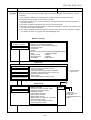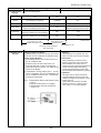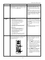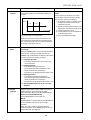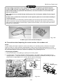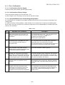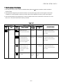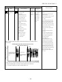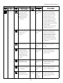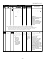
1
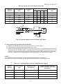
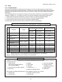
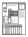
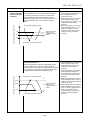
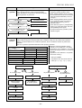
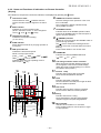
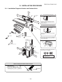
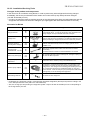
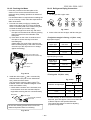
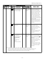
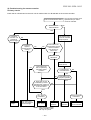
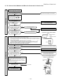
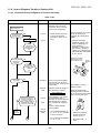
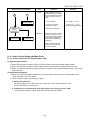
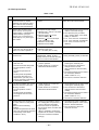
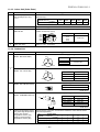
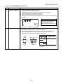
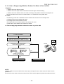
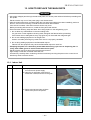
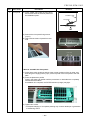
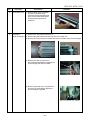
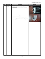
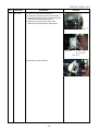
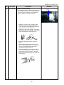
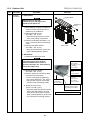
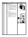
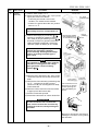
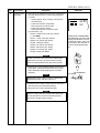
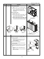
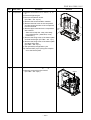
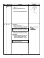
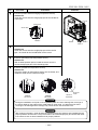
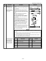
FILE NO. SVM-11015 Diagnosis/Process flowchart A Item Contents Check Check winding resistance between phases of compressor, and resistance between outdoor frames by using a tester. B Replace control board assembly. Check compressor winding resistance. NG • Is not grounded. → OK if 10MΩ or more • Is not short-circuited between windings. → OK if 0.51Ω → 0.57Ω (Check by a digital tester.) • Winding is not opened. OK Replace control board. Summary Remove connector CN300 of the outdoor fan motor, turn on the power supply breaker, and perform the operation. (Stops though activation is prompted.) Operation Replace compressor. Check operation within 2 minutes 20 seconds after activation stopped. 11-9. How to Check Simply the Main Parts 11-9-1. How to Check the P.C. Board (Indoor Unit) (1) Operating precautions 1) When removing the front panel or the P.C. board, be sure to shut off the power supply breaker. 2) When removing the P.C. board, hold the edge of the P.C. board and do not apply force to the parts. 3) When connecting or disconnecting the connectors on the P.C. board, hold the whole housing. Do not pull at the lead wire. (2) Inspection procedures 1) When a P.C. board is judged to be defective, check for disconnection, burning, or discoloration of the copper foil pattern or this P.C. board. 2) The P.C. board consists of the following 2 parts a. Main P.C. board part : DC power supply circuit, Indoor fan motor control circuit, CPU and peripheral circuits, buzzer, and Driving circuit of louver. b. Indication unit of infrared ray receiving infrared ray receiving circuit, LED : To check defect of the P.C. board, follow the procedure described below. – 81 –