1
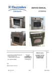
SERVICE MANUAL
COOKING
ã ELECTROLUX HOME PRODUCTS
Corso Lino Zanussi, 30
I - 33080 PORCIA /PN (ITALY)
Tel +39 0434 394850
Fax +39 0434 394096
Publication
number
599 38 74-62
IT/SERVICE/FV
WITH THE VISION
ELECTRONIC CONTROL
SYSTEM
Version for
Italy,
Europe, UK
(without roast spit)
SOI
Edition: 07.2007
SOI 07.07 FV
Wall Ovens
1/48
599 38 74-62
SOI 07.07 FV
2/48
599 38 74-62
TABLE OF CONTENTS
1 - INTRODUCTION ----------------------------------------------------------------------------------------------------- p.
1.1 - PURPOSE OF THIS MANUAL --------------------------------------------------------------------------------- p.
1.2 - ESD - ELECTROSTATIC DISCHARGE --------------------------------------------------------------------- p.
2 - THE VISION CONTROL SYSTEM ------------------------------------------------------------------------ p.
2.1 - INTRODUCTION --------------------------------------------------------------------------------------------------- p.
2.2 - GENERAL BLOCK DIAGRAM OF THE SYSTEM-------------------------------------------------------- p.
2.3 - CONTROL UNIT --------------------------------------------------------------------------------------------------- p.
2.4 - TOUCH SENSOR BOARDS ------------------------------------------------------------------------------------ p.
2.4.1 - POSITIONS OF THE TOUCH SENSOR BOARDS ON THE FRONT PANEL -------------- p.
2.5 - OVC2000 POWER BOARD (RELAYS) ---------------------------------------------------------------------- p.
2.5.1 - CONNECTIONS TO THE POWER BOARD --------------------------------------------------------- p.
2.5.2 - RELAYS AND THEIR FUNCTIONS-------------------------------------------------------------------- p.
2.6 - LIGHT BAR BOARD ---------------------------------------------------------------------------------------------- p.
2.7 - OVEN TEMPERATURE SENSOR ---------------------------------------------------------------------------- p.
2.7.1 - GRAPH OF TEMPERATURE VS SENSOR RESISTANCE ------------------------------------- p.
2.8 - TECHNICAL SPECIFICATIONS------------------------------------------------------------------------------- p.
2.8.1 - SOFTWARE VERSION ----------------------------------------------------------------------------------- p.
2.8.2 - TIMES---------------------------------------------------------------------------------------------------------- p.
2.8.3 - AUTOMATIC SHUTOFF ---------------------------------------------------------------------------------- p.
2.8.4 - DIMENSIONS------------------------------------------------------------------------------------------------ p.
2.8.4.1 - MINIMUM DIMENSIONS OF COMPARTMENT FOR BUILT-IN INSTALLATION -- p.
2.8.4.2 - USEFUL DIMENSIONS OF OVEN CHAMBER---------------------------------------------- p.
2.8.5 - POWER RATINGS ----------------------------------------------------------------------------------------- p.
3 - CONTROLS ------------------------------------------------------------------------------------------------------------ p.
3.1 - CONTROL PANEL ------------------------------------------------------------------------------------------------ p.
3.1.1 - DISPLAY ------------------------------------------------------------------------------------------------------ p.
3.1.2 - KEYS----------------------------------------------------------------------------------------------------------- p.
3.2 - DESCRIPTION OF DISPLAY----------------------------------------------------------------------------------- p.
3.2.1 - SYMBOLS SHOWN ---------------------------------------------------------------------------------------- p.
4 - HOW TO USE THE VISION CONTROL SYSTEM ------------------------------------------------ p.
4.1 - SETTING THE LANGUAGE ------------------------------------------------------------------------------------ p.
4.2 - SETTING CONTRAST AND BRIGHTNESS---------------------------------------------------------------- p.
4.3 - SETTING THE TIME OF DAY ---------------------------------------------------------------------------------- p.
4.4 - USING THE MENU ------------------------------------------------------------------------------------------------ p.
4.4.1 - HEATING INDICATOR ------------------------------------------------------------------------------------ p.
4.4.2 - RAPID HEATING INDICATOR -------------------------------------------------------------------------- p.
4.4.3 - RESIDUAL HEAT INDICATOR-------------------------------------------------------------------------- p.
4.4.4 - EXACT TEMPERATURE INDICATOR ---------------------------------------------------------------- p.
4.5 - OVEN LIGHT-------------------------------------------------------------------------------------------------------- p.
4.6 - THE FUNCTION MENU ------------------------------------------------------------------------------------------ p.
4.6.1 - TABLE OF PRESET TEMPERATURES -------------------------------------------------------------- p.
4.7 - ASSISTED COOKING MENU ---------------------------------------------------------------------------------- p.
4.7.1 - TABLE OF WEIGHTS ------------------------------------------------------------------------------------- p.
4.8 - ASSISTED COOKING WITH WEIGHT AUTOMATIC---------------------------------------------------- p.
4.9 - ASSISTED COOKING WITH AUTOMATIC PROGRAMME-------------------------------------------- p.
4.10 - MANUAL COOKING -------------------------------------------------------------------------------------------- p.
4.11 - OVEN FUNCTION MENU -------------------------------------------------------------------------------------- p.
4.12 - USING OVEN FUNCTIONS ----------------------------------------------------------------------------------- p.
5 - THE “MY PROGRAMMES” MENU---------------------------------------------------------- p.
5.1 - STORING A PROGRAMME ------------------------------------------------------------------------------------ p.
5.2 - RECALLING A PROGRAMME--------------------------------------------------------------------------------- p.
6 - BASIC SETTINGS MENU -------------------------------------------------------------------------------------- p.
6.1 - USING BASIC SETTINGS--------------------------------------------------------------------------------------- p.
6.2 - AUTOMATIC CHANGE IN DISPLAY BRIGHTNESS ---------------------------------------------------- p.
6.3 - BASIC SETTINGS USED EVERY DAY---------------------------------------------------------------------- p.
6.3.1 - SET + GO ----------------------------------------------------------------------------------------------------- p.
6.3.2 - ACTIVATING THE SET+GO FUNCTION------------------------------------------------------------- p.
6.3.3 - HOW TO START SET+GO------------------------------------------------------------------------------- p.
6.3.4 - HEAT-AND-HOLD ------------------------------------------------------------------------------------------ p.
6.3.5 - SELECTING THE HEAT-AND-HOLD FUNCTION ------------------------------------------------- p.
6.3.6 - EXTRA TIME FUNCTION -------------------------------------------------------------------------------- p.
SOI 07.07 FV
3/48
5
5
5
6
6
6
8
10
11
12
13
14
15
16
16
17
17
17
17
17
17
17
17
19
19
19
20
21
21
22
22
22
22
23
24
24
24
24
24
25
26
27
29
30
30
31
31
32
33
33
34
35
36
36
36
36
36
37
37
37
38
599 38 74-62
6.3.7 - SELECTING THE EXTRA TIME FUNCTION-------------------------------------------------------- p.
6.3.8 - SERVICE FUNCTION ------------------------------------------------------------------------------------- p.
6.4 - ADDITIONAL FUNCTIONS ------------------------------------------------------------------------------------- p.
6.4.1 - MINUTE MINDER------------------------------------------------------------------------------------------- p.
6.4.2 - DURATION OR END TIME------------------------------------------------------------------------------- p.
6.4.3 - RESIDUAL HEAT FUNCTION on DURATION OR END TIME --------------------------------- p.
6.4.4 - COMBINING DURATION AND END TIME----------------------------------------------------------- p.
6.4.5 - KEY LOCK---------------------------------------------------------------------------------------------------- p.
6.4.6 - APPLIANCE LOCKED FUNCTION -------------------------------------------------------------------- p.
6.4.7 - AUTOMATIC SHUTOFF --------------------------------------------------------------------------------------- p.
6.5 - DEMO FUNCTION------------------------------------------------------------------------------------------------- p.
38
38
39
39
39
40
40
40
41
41
42
7 - ERROR CODES ----------------------------------------------------------------------------------------------------- p.
43
8 - DIAGNOSTIC TESTS -------------------------------------------------------------------------------------------- p.
44
44
44
45
45
45
45
46
46
8.1 - ACTIVATION-------------------------------------------------------------------------------------------------------- p.
8.2 - HEATING COMPONENTS -------------------------------------------------------------------------------------- p.
8.3 - CHECKING THE OVEN TEMPERATURE SENSOR----------------------------------------------------- p.
8.4 - DISPLAYING THE SOFTWARE VERSION----------------------------------------------------------------- p.
8.5 - DISPLAY TEST----------------------------------------------------------------------------------------------------- p.
8.6 - SETTING THE BRIGHTNESS---------------------------------------------------------------------------------- p.
8.7 - TO END THE TEST ----------------------------------------------------------------------------------------------- p.
8.8 - CHECKING THE ON / OFF KEY AT THE END OF THE TEST --------------------------------------- p.
9 - FUNCTIONAL DIAGRAM -------------------------------------------------------------------------------------- p.
9.1 - LEGEND FOR DIAGRAM --------------------------------------------------------------------------------------- p.
9.2 - FUNCTIONAL DESCRIPTION OF OVEN ------------------------------------------------------------------- p.
SOI 07.07 FV
4/48
47
48
48
599 38 74-62
1 - INTRODUCTION
1.1 - THE PURPOSE OF THIS MANUAL
The purpose of this manual is to provide basic information for troubleshooting (with the aid of troubleshooting
manual no. 599387467) and repairing ovens equipped with the VISION electronic control system.
1.2 - ESD - ELECTROSTATIC DISCHARGE AND ITS EFFECT ON THE COMPONENTS
The interface for the control unit is not fitted with an internal device to protect against electrostatic discharge.
When effecting repairs, therefore, the service engineer must check for stabilization of the potential on the
oven casing (i.e. discharge any static electricity by touching the oven casing) in order to prevent the
possibility of overload, which might damage the circuit boards.
The same care is necessary when handling circuit boards supplied as spare parts (i.e. not yet fitted to the
appliance), which must be removed from the protective bag in ESD only after stabilizing the potential (i.e.
discharging any static electricity) and only then installed in the appliance.
Important: The theory behind the process of electrostatic charge and discharge is not discussed in this
Manual, since the tangible effects are considered to be more important. However, the effects are felt
frequently when touching a metal handle and feeling the electrostatic discharge in the form of a minor shock.
But what happens when stabilization of the potential takes place with semi-conductor components (i.e.
components on a circuit board, such as integrated circuits, microprocessors etc.)?
Stabilization of the potential takes place across the internal structure of the semi-conductor component. This
does not necessarily lead to the immediate destruction of the component; subsequent malfunctions across
damaged internal connections may be more harmful, and these occur only as a result of overheating or
current overloads.
It is true that almost all sensitive semi-conductor components (such as MOS circuits) have been improved by
the addition of protective measures, but the internal structures of these components are today smaller than,
for example, ten years ago, which tends to increase their sensitivity to the previous levels.
Important
Which components are susceptible to damage by static electricity during repairs?
All circuit boards with control and command accesses (door switches, food probes etc.), exposed
connections and microprocessors, and other circuits with that can be freely accessed.
Examples:
-
Programming units connected to the food probe and the door switch
Programming units whose processors are accessible (due to their high costs, the protective systems are
only partially effective)
W.O.E.C. control units
S.O.E.C. control units
C.H.E.C. control units
KRONOS control units
R.H.E.A. control units
AVANTGARDE control units
VISION control units
SOI 07.07 FV
5/48
599 38 74-62
2 - THE VISION CONTROL SYSTEM
2.1 - INTRODUCTION
The Vision control system is an integrated system for controlling ovens. It consists of an electronic
programming unit controlled by a microprocessor that is programmable (using a personalised programme).
The system enables the user to choose the heating element(s), cooking temperature and time, and cooking
programmes that are pre-programmed at the factory, but which can also be customized for special cooking
procedures. The system is also equipped with graphic symbols, multilingual wording, and error codes that
facilitate troubleshooting when a malfunction occurs.
2.2 - GENERAL BLOCK DIAGRAM OF THE SYSTEM
The system is composed of a number of components and can be depicted schematically as shown in Fig. 1.
The control logic (hardware and software) for the system is incorporated into the control unit.
This unit consists of a circuit board with touch sensors for system control, a display, and a buzzer.
The power board directly controls all electrical loads through a series of relays.
The sensors (oven sensor, and meat temperature sensor if used) send information about the various
temperatures to the system, which uses the information to control the appliance in the best way possible.
A circuit board that powers the light bar is also connected to the control unit.
LIGHT BAR
LIGHT BAR
BOARD
CONTROL UNIT
LEFT
TOUCH
SENSOR
BOARD
DISPLAY
BUZZER
RIGHT
TOUCH
SENSOR
BOARD
µP
POWER BOARD
SENSORS
(oven sensor,
meat sensor,
etc. )
µP
LOADS
(heating
elements, fans
etc.)
Fig. 1
NOTE: The control unit and the power board are equipped with circuitry that can be programmed using
suitable software. These boards are programmed at the factory.
SOI 07.07 FV
6/48
599 38 74-62
SOI 07.07 FV
7/48
599 38 74-62
2.3 - CONTROL UNIT
The control unit contains a low-voltage board that includes the logic circuitry, a display and a buzzer.
This module is connected to the power board (relays) by a set of connectors and a power cable.
The memory in the system contains custom settings which have been programmed for the appliance that the
system is connected to.
It also features self-testing and automatic diagnosis of malfunctions. In case of malfunction, an error code
with an informative message is displayed, and system functions may be shut down.
The functions performed by the control unit depend on its programming.
The unit is enclosed in a plastic housing that is installed on the front panel of the appliance.
CONNECTION
TO LIGHT BAR
CONNECTION
TO
OVC2000
POWER
BOARD
TO LEFT TOUCH
SENSOR BOARD
TO RIGHT TOUCH
SENSOR BOARD
Fig. 2
Fig. 3
BA01 - NOT USED (CONNECTION TO OVC1000)
BI3 - CONNECTION TO OVC2000 POWER BOARD
BI5 - CONNECTION TO LIGHT BAR BOARD
BI6 - NOT USED (CONNECTION FOR CONTROLLING DIFFERENT LEVELS IN THE OVEN)
BM01 - NOT USED (FOR FACTORY PROGRAMMING)
BP01 - NOT USED (FOR FACTORY PROGRAMMING)
BS01 - NOT USED
BT01 - CONNECTION TO LEFT TOUCH SENSOR BOARD
BT02 - CONNECTION TO RIGHT TOUCH SENSOR BOARD
BT03 - NOT USED
SOI 07.07 FV
8/48
599 38 74-62
Circuit board for Vision control unit
Fig. 4
Circuit board with its plastic housing
Fig. 5
1 - DISPLAY
2 - VISION CONTROL BOARD
3 - PLASTIC HOUSING
SOI 07.07 FV
9/48
599 38 74-62
2.4 - TOUCH SENSOR BOARDS
This oven is equipped with a control system that uses touch sensors.
To enter commands, two touch sensor boards are used instead of the classic buttons that control switches
on the control unit.
The touch system consists of two sensor boards that are glued onto the back of a small front panel made of
glass. The boards can recognize a finger at a distance of approx. 4 mm (the thickness of the glass panel)
from the sensors.
Each sensor board has 5 switch units with touch sensors.
The functions of the various keys are set by the software in the control unit.
Fig. 6
Fig. 7
SOI 07.07 FV
10/48
599 38 74-62
2.4.1 - POSITIONS OF THE TOUCH SENSOR BOARDS ON THE FRONT PANEL
Fig. 8
1 - GLASS FRONT PANEL
2 - RIGHT TOUCH SENSOR BOARD
3 - LEFT TOUCH SENSOR BOARD
4 - LIGHT BAR
RIGHT TOUCH SENSOR BOARD
LEFT TOUCH SENSOR BOARD
CONNECTION
TO CONTROL
UNIT
CONNECTION
TO CONTROL
UNIT
Fig. 9
SOI 07.07 FV
Fig. 10
11/48
599 38 74-62
2.5 - OVC2000 POWER BOARD (RELAYS)
The power board controls the heating elements, the convection fan, the cooling fan and the oven light
according to the information received from the control/display board.
The power board is composed of a power supply section (which is also used to supply low voltage to the
control/display board) and eleven relays that control the heating elements and low power components (oven
lamp, fans and roast spit) in accordance with the software configuration of the model involved.
All the functions on the board are controlled by an internal microprocessor.
A door lock system for the self-cleaning function may also be connected to the power board.
The main connections to the power board are illustrated below (see Fig. 11).
CONTROL UNIT
OVEN SENSOR
(PT500)
NETWORK INPUT
MAIN RELAY
OUTPUT
PHASE INPUT
FOR LOW
VOLTAGE LOADS
HEATING
ELEMENTS
LOW POWER
LOADS
Fig. 11
Here are the positions of the relays and connections.
Fig. 12
SOI 07.07 FV
12/48
599 38 74-62
2.5.1 - CONNECTIONS TO THE POWER BOARD
Here are the positions of the various connections, with descriptions of their functions.
Fig. 13
REFERENCE
BC1
BC2
BD1
BG1
BL1
BL2
BL4
BM1
BR1
BR2
BR3
BR12
BR4
BR5
BR6
BR8
BR9
BR10
BR7
BR11
BR13
BR14
BP1
DESCRIPTION
CONTROL UNIT
NOT USED
NOT USED
NOT USED
LOW POWER LOADS
NOT USED
PHASE INPUT FOR LOW POWER LOADS
NOT USED
POWER SUPPLIED FROM MAIN RELAY
POWER SUPPLIED FROM MAIN RELAY
SWITCHED OUTPUT FROM MAIN RELAY
SWITCHED OUTPUT FROM MAIN RELAY
PHASE INPUT
HEATING ELEMENT FOR FAN COOKING
TOP HEATING ELEMENT
NEUTRAL
BOTTOM HEATING ELEMENT
HEATING ELEMENT FOR GRILL
NOT USED
NOT USED
NEUTRAL
GROUND
OVEN SENSOR (PT500) (*)
CONNECTOR
GREEN
WHITE
WHITE
WHITE
WHITE
WHITE
FASTON
GREEN
APD - 1ST OUT (2
POLE)
APD - 1ST IN (2 POLE)
FASTON
WHITE - 6 POLE
FASTON
FASTON
FASTON
FASTON
WHITE
(*) NOTE: When installing the connector, be sure to position it on the right-hand side.
Fig. 14
1 - SENSOR CONNECTOR PLUG
2 - SENSOR CONNECTOR SOCKET
SOI 07.07 FV
13/48
599 38 74-62
2.5.2 - RELAYS AND THEIR FUNCTIONS
Here are the positions of the relays, with descriptions of their functions:
Fig. 15
REFERENCE
REL1
REL4
REL5
REL8
REL9
REL10
REL11
REL12
REL13
REL15
REL16
SOI 07.07 FV
DESCRIPTION
MAIN RELAY
RELAY FOR CIRCULAR HEATING ELEMENT
RELAY FOR GRILL HEATING ELEMENT
RELAY FOR TOP HEATING ELEMENT
RELAY FOR BOTTOM HEATING ELEMENT
RELAY FOR ROAST SPIT MOTOR (NOT USED)
RELAY FOR CONVECTION FAN
RELAY FOR DUAL-SPEED COOLING FAN (NOT USED)
RELAY FOR COOLING FAN
RELAY FOR OVEN LAMP
RELAY FOR DOOR LOCK (NOT USED)
14/48
599 38 74-62
2.6 - LIGHT BAR BOARD
The light bar consists of a fluorescent bar illuminated by two LEDs.
These LEDs are powered by the light bar board, which is connected to the power mains and to the control
unit.
Fig. 16
BR01 - POWER CONNECTOR FOR THE LEDs ON THE LIGHT BAR
BR02 - CONNECTOR FOR DISPLAY BOARD
BR03 - NEUTRAL CONNECTION FROM POWER MAINS
BR04 - PHASE CONNECTION FROM POWER MAINS
BR05 - NOT USED
BR06 - NOT USED
BR07 - NOT USED
BR08 - NOT USED
Fig. 17
SOI 07.07 FV
15/48
599 38 74-62
2.7 - OVEN TEMPERATURE SENSOR
To control oven temperature, the VISION system uses a temperature sensor mounted on a bracket which is
screwed onto the oven muffle.
A PT500 resistance-type platinum sensor provides the control board with the information that is required for
the following functions:
Cycling the heating elements until they reach the desired temperature
Shutting down heating elements in case of overheating or sensor malfunction
Delaying cooling fan startup and shutdown
Recognizing relay malfunctions
The temperature sensor is hermetically sealed in a metal sheath, which must be connected to earth.
Fig. 18
1 - PT500 SENSOR
2 - MOUNTING BRACKET WITH
EARTH CONNECTION
3 - CONNECTING CABLE
NOTE: When connecting the
oven sensor to the power
board, make sure the
connector is in the correct
position
(see Fig. 14, p. 12).
2.7.1 - GRAPH OF TEMPERATURE VS SENSOR RESISTANCE
RESISTENZA Ω
Fig. 19
SOI 07.07 FV
TEMPERATURA °C
16/48
599 38 74-62
2.8 - TECHNICAL SPECIFICATIONS
2.8.1 - SOFTWARE VERSION
This version of Vision is equipped with firmware
EBAIG313 V21IG003 and is identified by the following
indication on the display:
Fig. 20
NOTE: The last three digits of the firmware number (a double series of numbers that appear on the display
- in this case “313” and “003)” indicate the modification level. Although these digits may change, the
modified firmware is compatible with preceding control units having the same part number. The number
appearing on the last line (in this case “49” ) shows total hours of oven use.
2.8.2 - TIMES
Time format
Maximum cooking time
24 hours
23 hours 59
minutes
23 hours 59
minutes
Minute Minder
2.8.3 - AUTOMATIC SHUTOFF
The automatic shutoff function is programmed as follows:
Temperature set
30 – 115 °C
120 – 195 °C
200 – 245 °C
250 – 280 °C
Automatic shutoff
After 12 hours 30 minutes
After 8 hours 30 minutes
After 5 hours 30 minutes
After 3 hours
2.8.4 - DIMENSIONS
2.8.4.1 - MINIMUM DIMENSIONS OF COMPARTMENT FOR BUILT-IN INSTALLATION
Height
Width
Depth
593 mm
560 mm
550 mm
2.8.4.2 - USEFUL DIMENSIONS OF OVEN CHAMBER
Height
Width
Depth
Useful volume
335 mm
395 mm
400 mm
53 lt
2.8.5 - POWER RATINGS
Top heating element
Bottom heating element
Top + bottom heating element
Single grill heating element
Dual grill heating element
Rear element (circular)
Oven lamp
Cooling fan (tangential)
Oven fan (convection)
Maximum total power requirement
Voltage requirement (50 Hz)
SOI 07.07 FV
800 W
1000 W
1800 W
1680 W
2450 W
2000 W
25 W
25 W
30 W
2500 W
230 V
17/48
599 38 74-62
SOI 07.07 FV
18/48
599 38 74-62
3 - CONTROLS
3.1 - CONTROL PANEL
Fig. 21
1
2
3
4
- CONTROL PANEL
- DISPLAY
- LIGHT BAR
- TOUCH-KEY CONTROLS
3.1.1 - DISPLAY
Fig. 22
1
2
3
4
5
- MENU OPTION SYMBOL (WITH LEVELS)
- TIME OF DAY
- HEATING DISPLAY
- TIMED FUNCTIONS
- TEMPERATURE / WEIGHT
SOI 07.07 FV
19/48
599 38 74-62
3.1.2 - KEYS
Fig. 23
REF.
SYMBOL
DESCRIPTION OF TOUCH KEYS
1
Turns appliance on and off
2
Scrolls UP
3
4
Displays main menu
Scrolls DOWN
5
Increases value (of temperature, time, weight, etc.)
6
Selects time functions and supplementary functions.
7
8
Decreases value (of temperature, time, weight, etc.)
SOI 07.07 FV
Confirms a selection or accesses a submenu
20/48
599 38 74-62
3.2 - DESCRIPTION OF DISPLAY
The Vision electronic control system has a graphic display whose symbols indicate the functions of the
appliance. It also shows animated cooking icons that may differ, depending on the software installed on the
appliance in question.
3.2.1 - SYMBOLS SHOWN
Here are the principal symbols for the functions which are available on this version of the Vision electronic
control system.
Symbol
Indication
(Example)
Function
Minute Minder
4:30
The Minute Minder is operating
Time of day
10:00
Displays the time
Duration
1:00
Displays cooking time
14:05
Displays the time when cooking ends
0:45
Displays the time when cooking began
End Time
Start time
Temperature
Weight
1.5 kg
Heat-andHold
80°C
SOI 07.07 FV
Displays the temperature in the oven
Rapid heating is on (for reduced heating time)
Meanings:
- The weight automatic function is selected
- The weight can be changed
The Heat-and-Hold function is on
21/48
599 38 74-62
4 - HOW TO USE THE VISION CONTROL SYSTEM
4.1 - SETTING THE LANGUAGE
LANGUAGE
English
When the appliance is plugged in, the
following appears on the display:
- The logo of the company
- The software version and total operating
time
- The word “LANGUAGE”
Fig. 24
1. Use the
and
keys to select the
desired language.
to confirm the selected
2. Press
language.
NOTE: The language menu appears only when the appliance is turned on for the first time or after the
Factory Test is run.
4.2 - SETTING CONTRAST AND BRIGHTNESS
After the language has been set, “set contrast” and “set brightness” will appear on the display.
1. Use the
and
2. Press
to confirm the levels selected.
keys to select the desired levels of contrast and brightness.
4.3 - SETTING THE TIME OF DAY
After the contrast and brightness have been set, “set time” will appear on the display.
1. Use the
and
keys to set the
hour of the current time of day.
2. Press
to confirm.
SET TIME OF DAY
+/- to adjust, OK to confirm
3. Use the
and
keys to set the
minutes of the current time of day.
4. Press
to confirm.
Fig. 25
SOI 07.07 FV
22/48
599 38 74-62
4.4 - USING THE MENU
My Programme
key to turn the appliance
1. Press the
on. The main menu will appear on the
display.
Assisted Cooking
Heating Functions
Fig. 26
Specials
2. Use the
and
scroll keys to
select the desired submenu.
Pork/Veal
to access the selected
3. Press
submenu.
The corresponding submenu will be
displayed.
Fig. 27
Beef/Game/Lamb
Note: To return to the main menu, press
wherever it appears.
Note: The Back menu option located at the end of most menus can be used to move to a higher menu.
Note: Any operation can be interrupted by pressing
SOI 07.07 FV
to return to the main menu.
23/48
599 38 74-62
4.4.1 - HEATING INDICATOR
When an oven function is activated, the
gradually elongating bar shows the
progress of the heating process.
Fig. 28
4.4.2 - RAPID HEATING INDICATOR
With some oven functions (such as Turbo
Grill) the heating time is reduced by an
automatic rapid heating feature (which
uses multiple heating elements during
initial heating).
A striped bar moves from left to right until
the desired temperature is reached.
Fig. 29
4.4.3 - RESIDUAL HEAT INDICATOR
When an oven function is terminated, the
residual heat in the oven is displayed.
Fig. 30
4.4.4 - EXACT TEMPERATURE INDICATOR
During heating, the exact temperature in
degrees is shown for 5 seconds instead
of the bar on the display.
Afterward, press
and
at the same
time to display the exact temperature.
Fig. 31
4.5 - OVEN LIGHT
The oven light is used to illuminate foods inside the oven and is the first function that appears when the oven
is turned on.
To access the oven light function, simply
turn on the appliance using the
ON/OFF
key.
Fig. 32
SOI 07.07 FV
24/48
599 38 74-62
4.6 - THE FUNCTION MENU
• The oven function menu appears on the display when the appliance is turned on.
• Use the
and
scroll keys to highlight the desired oven function. The menu bar shows the current
position within the menu.
Here is how the oven functions are arranged
Main menu
Submenu
Assisted Cooking
Pork/Veal
Beef/Wild Game/Lamb
Poultry
Fish
Cake/Tart
Pizza/Pie/Bread
Casserole/Au Gratin cooking
Convenience
Special Functions
Cooking Functions
Oven Light
Fan Cooking
Conventional Cooking
Pizza Setting (30% bottom element
and 70% convection)
Turbo Grill
Grill
Dual Grill
Bottom Heat (bottom heating element)
Slow cooking
My Programmes
SOI 07.07 FV
1 - My Programmes
2 - My Programmes
…
Rename Programme
25/48
599 38 74-62
Main menu
Basic Settings
Submenu
Set time of day
Display time of day
Set+Go
Heat-and-Hold
Extra Time
Contrast of display
Brightness of display
Language
Signal volume
Volume of tones
Alarm/error tones on-off
Service
Factory settings
4.6.1 - TABLE OF PRESET TEMPERATURES
A preset temperature is suggested when a cooking function is selected. This temperature can be changed
by the user.
Cooking function
Preset
temperature
Oven Light
30°C
Fan Cooking
150°C
Conventional Cooking
200°C
Pizza Setting
200°C
Turbo Grill
180°C
Grill
250°C
Dual Grill
250°C
Bottom Heat (bottom heating
element)
150°C
Slow Cooking
(*)
(*) The user can choose between 2 settings that cannot be changed:
Setting 1: 120°C / 80°C
Setting 2: 150°C / 80°C
SOI 07.07 FV
26/48
599 38 74-62
4.7 - ASSISTED COOKING MENU
Category
Pork / Veal
Dish
Roast pork
Veal
Pork loin
Ossobuco
Pork shin
Stuffed veal breast
Pork shoulder
Meat loaf
Veal roast
Beef / Wild Game /
Lamb
Poultry
Beef
Roast wild game
Scandinavian beef
Rabbit
Roast beef
Wild boar
Marinated beef
Roast lamb
Loin of wild game
Lamb joint, medium
Roast wild game
Leg of lamb
Whole chicken
Chicken thigh
Whole turkey
Coq au Vin
Whole duck
Roast duck al’orange
Whole goose
Stuffed chicken
Poultry
Fish
Whole fish
Stuffed calamari
Filet of fish
Steamed fish
Baccalà
Jansson’s Temptation
Fish in salt
SOI 07.07 FV
27/48
599 38 74-62
Category
Cake/Tart
Pizza / Pie /
Bread
Dish
Lemon sponge cake
Ring cake
Swedish cake
Savarin Cake
Cookies
Brownies
Cheesecake
Muffins
Fruitcake
Sweet tart
Streusel cake
Carrot cake
Rich yeast plait
Almond cake
Yeast plait
Fruit tart
Pizza
Cheese pastry
Onion tart
White bread
Quiche Lorraine
Whole wheat bread
Goat cheese flan
Russian cake
Cheese flan
Casserole / Au
Gratin
Convenience Foods
Lasagne
Pasta au gratin
Cannelloni
Vegetables au gratin
Potatoes au gratin
Casserole
Moussaka
Cabbage casserole
Frozen pizza
Frozen American pizza
Bread / Sandwiches
Frozen bread / Sandwiches,
lightly browned
Frozen apple strudel
Frozen filet of fish
Chicken wings
Frozen lasagne / Cannelloni
Cold pizza
Frozen pizza snacks
French fries
Croquettes
Hash browns
Special Functions
SOI 07.07 FV
Defrost
Dry
Keep warm
Preserve
Warm plates
28/48
599 38 74-62
4.7.1 - TABLE OF WEIGHTS
The weight of dishes marked with the
symbol can be set. Here is a table of weights:
Category
Dish
Pork / Veal
Roast pork
Pork loin
Veal roast
Beef
Scandinavian beef
Roast beef
Loin of wild game
Roast wild game
Roast lamb
Lamb joint, medium
Whole chicken
Whole turkey
Whole duck
Whole goose
Whole fish
Beef / Wild
Game /
Lamb
Poultry
Fish
SOI 07.07 FV
Preset
weight
gr
1500
1500
1500
1000
1000
1000
1500
1500
1500
1500
1200
3000
1600
3000
700
29/48
Minimum
weight
gr
800
800
800
800
800
800
800
800
800
800
800
800
800
900
300
Maximum
weight
3000
3000
2500
2500
2000
2500
3000
3000
3000
2500
2000
6000
2500
4500
1000
Adjusts in
steps of
gr
100
100
100
100
100
100
100
100
100
100
100
100
100
100
100
599 38 74-62
4.8 - ASSISTED COOKING WITH WEIGHT AUTOMATIC
Cooking time is automatically set when the weight of the dish is entered.
Example:
Back
1. Using the
and
scroll keys,
select the Assisted Cooking menu
option, the desired category and the
dish.
2. Press
to confirm.
Automatic weight
Manual
Fig. 33
3. Using the
and
scroll keys,
select Weight Automatic.
4. Press
to confirm.
Fig. 34
5. Using the
and
scroll keys,
set the weight of the dish. The setting
is made in steps of 0.1 kg (see the
weight table on p. 27).
The automatic programme will now
start.
A signal will sound as soon as the
programme ends.
6. Press any key to shut off the signal.
4.9 - ASSISTED COOKING WITH AUTOMATIC PROGRAMME
All settings are preset at the factory and cannot be changed.
Example:
1. Using the
and
scroll keys,
select the Assisted Cooking menu
option, the desired category and the
dish.
2. Press
Back
Recipe automatic
Manual
to confirm.
3. Using the
and
scroll keys,
select Automatic Programme.
Fig. 35
to confirm.
4. Press
5. The automatic programme will now
start.
As soon as the programme ends, a
signal will sound.
6. Press any key to shut off the signal.
Fig. 36
SOI 07.07 FV
30/48
599 38 74-62
4.10 - MANUAL COOKING
With manual cooking, the optimum settings (oven function and temperature) are automatically set for the
corresponding dish. However, these settings can be changed by the user when the weight of the dish is
unknown or when a personal recipe is used.
Example
1. Using the
and
scroll keys,
select the Weight Automatic menu
option.
to confirm.
2. Press
3. Using the
and
select Manual.
4. Press
scroll keys,
Fig. 37
to confirm.
The desired settings for the selected function can now be made.
4.11 - OVEN FUNCTION MENU
Oven function
Use
Heating element / fan
Oven Light
To illuminate the oven
Oven lamp
Fan Cooking
For cooking on a maximum of three
levels at the same time.
Set the oven temperature 20-40°C lower
than for Conventional Cooking.
For cooking and roasting on one level.
Convection element and
convection fan.
To bake dishes on one level that require
greater browning and a crispy bottom.
Set the oven temperature 20-40°C lower
than for Conventional Cooking.
To roast large pieces of meat or poultry
on one level.
This function is perfect for au gratin
cooking and browning.
To grill thin foods placed at the centre of
the grill, and to toast.
30% bottom element, 70%
convection element, and
convection fan.
Conventional
Cooking
Pizza Setting
Turbo Grill
Grill
Top element and bottom
element.
Grill element, top element
and convection fan.
Grill element.
Dual Grill
To grill foods in large quantities, and to
toast.
Grill element and top
element.
Bottom Heat
To finish cooking tarts with crumbly
bottoms.
To prepare roasts that are especially
tender and flavourful.
Bottom element.
Slow Cooking
SOI 07.07 FV
31/48
Convection element and
convection fan.
599 38 74-62
4.12 - USING OVEN FUNCTIONS
Example:
1. Press the
on.
Slow cooking
Fan cooking
Conventional cooking
key to turn the appliance
2. Use the
and
keys to select
the Oven Function menu option.
3. Press
to confirm.
Fig. 38
4. Using the
and
scroll keys,
select the Fan Cooking function.
5. Press
to confirm.
Fig. 39
A signal will sound when the oven is
preheated.
NOTE: The oven is heating up when:
-
The oven function symbol is moving.
The oven light turns on.
The corresponding heating element turns on (for example, the fan).
SOI 07.07 FV
32/48
599 38 74-62
5 - THE “MY PROGRAMMES” MENU
The “My Programmes” menu is used to store personalised programmes.
Submenu
1 - My Programmes
2 - My Programmes
…
Rename programme
Description
To store the optimum settings for personalised programmes.
To rename stored programmes.
NOTE: Up to 20 programmes can be stored.
5.1 - STORING A PROGRAMME
Example:
1. Select the desired oven function or
Assisted Cooking with the desired
settings.
2. During or after the oven function or
Assisted Cooking, press
SAVE
Press OK to save
until “Save” appears on the
display.
to confirm. The next free
3. Press
memory area will now be displayed.
Fig. 40
to confirm.
4. Press
5. The name of the programme can now
be written. The first letter will flash.
6. Using the
and
desired letter.
GRANNIES CAKE
MY PROGRAMME
Back
keys, select the
Fig. 41
7. Using the
and
scroll keys,
move the cursor toward the right or
left.
The next letter will flash and can be
changed. Proceed in the same way
for the other letters.
ANNA PROGRAMME
To select, +/- to adjust,
To store press OK.
Fig. 42
8. After the name of the programme has
GRANNIES CAKE
ANNA ROAST
Back
to confirm.
been written, press
The programme will now be stored.
Fig. 43
SOI 07.07 FV
33/48
599 38 74-62
5.2 - RECALLING A PROGRAMME
Example
1. Press the
on.
key to turn the appliance
2. Using the
and
keys, select
the My Programmes menu option.
3. Press
to confirm.
4. Using the
and
scroll keys,
select the stored programme.
5. Press
to confirm.
Fig. 44
The stored programme will now begin. Its
programmed settings will be used.
SOI 07.07 FV
34/48
599 38 74-62
6 - BASIC SETTINGS MENU
NOTE: A number of basic settings can be changed independently from the corresponding application in the
oven. Settings can be changed only when no oven function is selected.
Set time
Setting
Display
12:15
Description
Used for setting the current time.
Display time
- On
The time of day is displayed when the
appliance is shut off.
The time of day is shown when the appliance is
shut off, but the display is turned off to save
energy.
The Set+Go function is displayed in the Select
Option window and can be activated.
The Set+Go function is not displayed in the
Select Option window.
The Heat-and-Hold function is displayed in the
Select Option window and can be activated.
The Heat-and-Hold function is not displayed in
the Select Option window.
Selects and cancels the Extra Time function.
- Off
Set+Go
- On
- Off
Heat-and-Hold
- On
- Off
Extra Time
Contrast of Display
- On
- Off
1 ….. 10
Brightness of Display
1 ….. 10
Sets the brightness of the display in steps.
Language
- Italiano
- ….
1 ….. 10
Selects and sets of the language used on the
display.
Increases the volume of the key tones and the
signal in steps.
Each keypress is confirmed with a tone when
the key is pressed: selects and cancels key
tones.
An alarm tone is sounded if a command cannot
be executed: selects and cancels alarm tones
Displays software version and configuration.
Signal volume
Volume of Key Tones
- On
- Off
Alarm/Error Tones
- On
- Off
EBAIG313
V21IG003
Service
Factory Settings
SOI 07.07 FV
Sets the contrast of the display in steps.
Resets all settings (and My Programmes) to
factory values.
35/48
599 38 74-62
6.1 - USING BASIC SETTINGS
Example
1. Using the
and
keys, select
the Basic Settings function.
2. Press
to confirm.
KEY TONES
3. Using the
and
scroll keys,
select the setting you wish to change.
+/- to adjust, OK to confirm
to confirm. The current
4. Press
value of the setting will now appear on
the display.
5. Using the
and
desired value.
keys, select the
OFF
ON
Fig. 45
to confirm.
6. Press
The setting has now been changed.
6.2 - AUTOMATIC CHANGE IN DISPLAY BRIGHTNESS
When the appliance is turned off, the display dims from 22:00 in the evening to 6:00 in the morning to save
energy.
6.3 - BASIC SETTINGS USED EVERY DAY
6.3.1 - SET+GO
The Set+Go allows you to set all the settings for a given oven function and then to start the oven at a later
time.
Sample application:
In the morning, you prepare a dish and make all the settings that are necessary for cooking it in the oven.
Your child comes home at noon, places the dish in the oven and presses any key. The oven turns on with
the settings you made previously.
Important:
- The cooking time must be set
6.3.2 - ACTIVATING THE SET+GO FUNCTION
Example
1. Select the oven function with the
desired settings.
Press OK to activate
repeatedly until “Set+Go”
2. Press
appears on the display.
to confirm. The Set+Go
3. Press
function is now activated.
Fig. 46
Set+Go is active
Press any key to start
Fig. 47
SOI 07.07 FV
36/48
599 38 74-62
6.3.3 - HOW TO START SET+GO
1. Press any key (except
).
The selected oven function will start.
A signal will sound as soon as the
function ends.
2. Press any key to silence the signal.
NOTE: The Key Lock operates while the
function selected with Set+Go is in
progress (see the paragraph on the Key
Lock).
NOTE: Use the Basic Settings menu to select and cancel the
Set+Go function.
6.3.4 - HEAT-AND-HOLD
The Heat-and-Hold function keeps prepared dishes warm for 30 minutes after cooking or roasting is
completed.
This function is particularly useful when guests are late.
Requirements for the Heat-and-Hold function:
- The temperature must be set higher than 80°C.
- The duration must be set.
6.3.5 - SELECTING THE HEAT-AND-HOLD FUNCTION
1. Select the desired oven function.
2. Press
repeatedly until “Heat-andHold” appears in the window.
to confirm.
3. Press
The Heat-and-Hold function is now
active.
4. As soon as the oven function ends, A
signal will sound and the Heat-andHold function will begin.
The selected oven function will now
continue at 80°C for 30 minutes.
After the 30 minute period, the oven will
shut off.
NOTE: The Heat-and-Hold will remain
active regardless of the oven function
selected, which can be changed as
desired.
SOI 07.07 FV
HEAT + HOLD
Press OK to activate
Fig. 48
NOTE: Use the Basic Settings menu to select and cancel the
Heat-and-Hold function.
37/48
599 38 74-62
6.3.6 - EXTRA TIME FUNCTION
When Extra Time is selected, the time for the selected function (the last function selected) will be extended
for the programmed Extra Time when the function ends.
Important:
- This function can be selected on all oven functions with Duration or Weight Automatic.
Use the Basic Settings menu to select and cancel the Extra Time function.
6.3.7 - SELECTING THE EXTRA TIME FUNCTION
The oven function ends.
A signal sounds and a message is
displayed.
).
1. Press any key (except
2. The Extra Time message will be
displayed for about 5 minutes.
3. Press
to select Extra Time.
4. Using the
and
keys, set the
duration of Extra Time.
or
5. Start Extra Time by pressing
let the function start automatically after
5 seconds.
The settings of the oven function will be
displayed with the new duration.
6.3.8 - SERVICE FUNCTION
The Service Function displays the software version and the configuration.
1. From the Basic Settings menu, select
Service using
and
keys.
to confirm.
3. Press
4. The software version will appear on
the display, along with total hours of
oven operation (on the last line - see
Fig. 50).
Alarm/error tones
Service
Heating functions
Fig. 49
Fig. 50
SOI 07.07 FV
38/48
599 38 74-62
6.4 - ADDITIONAL FUNCTIONS
6.4.1 - MINUTE MINDER
A signal sounds when the time set on the Minute Minder expires.
This function does not affect oven operation.
A signal sounds and a message is
displayed.
repeatedly until “Minute
1. Press
Minder” appears on the display.
Using the
or
Minute Minder
keys, set the time.
to confirm, or wait 5
2. Press
seconds.
The last option selected and the
remaining time will now be displayed.
When 10% of the programmed time
remains, a signal will sound and a
message will be displayed.
3. Press any key (except
the signal.
Fig. 51
) to silence
Fig. 52
NOTE: The Minute Minder remains selected even if the oven function is changed or the appliance is shut
off.
6.4.2 - DURATION
OR END TIME
DURATION
To set the amount of time the oven will operate.
END TIME
To set the time of day when the oven will shut off.
1. Select the desired oven function.
Duration
repeatedly until
2. Press
“Duration/End Time” appears on the
display.
3. Using the
or
keys, set the
desired cooking time or the shutoff
time (23 hours 59
minutes, max.).
to confirm, or wait 5
4. Press
seconds.
The settings for the selected oven
function will now be displayed along
with the programmed duration and
shutoff time.
When the time expires, a signal will
sound and a message will be
displayed.
The oven will then shut off.
5. Press any key (except
the signal.
End Time
Fig. 53
Fig. 54
) to silence
NOTE: The programmed duration will not change regardless of the oven function selected. Thus, the oven
function can be changed as desired; however, the new function must not have a preset duration.
SOI 07.07 FV
39/48
599 38 74-62
6.4.3 - RESIDUAL HEAT FUNCTION on DURATION
OR END TIME
When the Duration
or End Time
function is used, the heating elements shut off when 90% of the
set or calculated time has elapsed. The residual heat in the oven is used to continue cooking until the end of
the preset time (from 3 to 20 minutes).
6.4.4 - COMBINING DURATION
The Duration
and End Time
oven automatically at a later time.
AND END TIME
functions can be used at the same time to turn on and shut off the
1. Select the desired oven function.
Duration
repeatedly until
2. Press
“Duration/End Time” appears on the
display.
3. Using the Duration
function, set
the time necessary to cook the dish
(for example, 1 hour).
4. Press
End Time
Fig. 55
to confirm.
5. Using the End Time
function, set
the time when the dish must be ready
(for ex. 14:05).
to confirm, or wait 5
6 Press
seconds.
The selected oven function will be
displayed for a few seconds with the
preset duration and shutoff time.
Fig. 56
Your oven is programmed and
will start at
A message will be displayed when the
programme has been set up.
Fig. 57
6.4.5 - KEY LOCK
Activating the key lock
1. Select the desired oven function.
KEY LOCK
repeatedly until “Key Lock”
2. Press
appears on the display.
Press OK to activate
to confirm.
3. Press
The key lock is now activated.
Deactivating the key lock
2. Press
Fig. 58
.
3. Press
to confirm.
NOTE: The Key Lock does not protect against accidental shutoff. The Key Lock is automatically
deactivated when the appliance is shut off.
SOI 07.07 FV
40/48
599 38 74-62
6.4.6 - APPLIANCE LOCKED FUNCTION (FOR CHILD PROTECTION)
The oven cannot be operated when the Appliance Locked function is activated.
Activating the Appliance Locked
function
No function can be selected when the
Appliance Locked function is activated.
and
at the same time
1. Press
until “Appliance locked” appears on
the display.
The Appliance Locked function is now
activated.
Appliance locked
Fig. 59
Deactivating the Appliance Locked
Function
and
at the same time
1. Press
until “Appliance unlocked” appears on
the display.
The Appliance Locked function is now
deactivated and the oven is ready for use.
Appliance unlocked
Fig. 60
6.4.7 - AUTOMATIC SHUTOFF
The oven will shut off automatically if it is not turned off or the temperature is not changed within a certain
period of time.
The oven will shut off automatically after:
12 hours and 30
at a temperature of
minutes
8 hours and 30
at a temperature of
minutes
5 hours and 30
at a temperature of
minutes
3 hours
at a temperature of
30 - 115 °C
120 - 195 °C
200 - 245 °C
250 - max°C
To turn the oven back on after an automatic shutoff:
Press
.
SOI 07.07 FV
41/48
599 38 74-62
6.5 - DEMO FUNCTION
This function is used to demonstrate the functions of the oven in stores or showrooms. No energy is
consumed, except for the energy used by the oven light.
To activate this function when the oven is off:
1 - Press and hold down
.
Fig. 61
2 - The oven will turn on and off, and a signal will sound.
Fig. 62
2 - Hold down the
and
keys until the signal sounds once again (see Fig. 63).
Fig. 63
3 - Press
to turn the oven on. The first function (oven light) will appear on the display together with
“DEMO” at the top of the frame (see Fig. 64). The Demo function is now operating.
Fig. 64
NOTE: The “Demo” function deactivates automatically when the oven is shut off.
SOI 07.07 FV
42/48
599 38 74-62
7 - ERROR CODES
The VISION system performs internal diagnostic tests. When a fault is detected, an error code will appear
on the display, as shown in Fig. 65.
The table below lists the various error codes:
ERROR CODE
F0
F1
F2
F3
F4
F5
F8
F9
F14
CAUSE OF ERROR
Internal error on the power board
Door cannot be locked
(self-cleaning ovens only)
Door cannot be unlocked
(self-cleaning ovens only)
Software error, malfunction on control unit (EEPROM)
Sensor resistance out of range (sensor open or shorted) for
more than 5 seconds
Temperature out of acceptable range
(> 350°C on normal ovens)
(> 530°C on self-cleaning ovens)
Communication interrupted between control unit and power
board
Software incompatibility between control unit and power
board
Software error
Here is how an error code appears on the display.
Example of an error code (F5):
Fig. 65
SOI 07.07 FV
43/48
599 38 74-62
8-
DIAGNOSTIC TESTS
The diagnostic programme (factory test) is a series of tests that are performed at the factory to check ovens
for proper operation. This procedure can be used to troubleshoot malfunctions.
8.1 - ACTIVATION
To start the factory test on this version, turn on the appliance and follow the procedure shown below before
making any settings (language, time):
When the Electrolux logo appears on the
display at start-up (see Fig. 66), press
and
at the same time.
Fig. 66
Hold down the keys until the screen
shown in Fig. 67 appears.
The factory test is now running.
Fig. 67
NOTE: If the above procedure is unsuccessful, unplug the appliance and repeat the operation.
8.2 - HEATING COMPONENTS
A test of the various heating components is the first diagnostic test that is run. The components are tested in
a series of four steps:
Fig. 68
To move to the next step, press
.
Fig. 69
The test sequence is as follows:
No.
SYMBOL
WORDING ON DISPLAY
DESCRIPTION
1
T clfL Lamp
Top element+ cooling fan + oven lamp
2
B clfL Lamp
Bottom element+ cooling fan + oven lamp
3
Rf clfL Lamp
Circular element + convection fan + cooling fan +
oven lamp
4
Gf clfL Lamp
Grill element +spit roast motor + cooling fan +
oven lamp
IMPORTANT : Pressing
SOI 07.07 FV
again will repeat the test sequence.
44/48
599 38 74-62
8.3 - CHECKING THE
KEY AND THE OVEN TEMPERATURE SENSOR
The temperature sensor is tested by measuring the current temperature in the oven.
. The
To start the sensor test, press
temperature detected in the oven will
appear on the display.
Fig. 70
8.4 - DISPLAYING THE SOFTWARE VERSION
To check the version of software installed:
Press
.
Fig. 71
NOTE: The number on the last line shows the total hours of oven operation.
8.5 - DISPLAY TEST
The display test consists of a number of levels of brightness, which are activated by pressing
:
HIGH
LOW
MEDIUM SPLIT
FRAME
Fig. 72
8.6 - SETTING THE BRIGHTNESS
Press
to bring up the brightness adjustment submenu.
Use
and
to check whether the
display brightness can be adjusted
correctly.
Fig. 73
SOI 07.07 FV
45/48
599 38 74-62
8.7 - TO END THE TEST
and the wording shown on
Press
the right will appear on the display.
Fig. 74
8.8 - CHECKING THE ON / OFF KEY AT THE END OF THE TEST
When “Factory test done” appears on the display, press ON / OFF
to exit the test mode. The time will
appear on the display, and the residual heat bar will also appear if oven temperature exceeded 40°C during
the tests.
Fig. 75
SOI 07.07 FV
46/48
599 38 74-62
9 - FUNCTIONAL DIAGRAM
Fig. 76
SOI 07.07 FV
47/48
599 38 74-62
9.1 - LEGEND FOR DIAGRAM
GROUND
L1
LEFT TOUCH SENSOR BOARD
LIGHT BAR
LIGHT BAR BOARD
M1
M3
NEUTRAL
PHASE
POWER BOARD
PT500 sensor
R1
R2
R3
R4
RIGHT TOUCH SENSOR BOARD
Th1
Th2
VISION DISPLAY BOARD
- EARTH
- OVEN LAMP
- COOLING FAN
- CONVECTION FAN
- OVC2000 POWER BOARD
- OVEN TEMPERATURE SENSOR
- CONVECTION ELEMENT
- TOP ELEMENT
- BOTTOM ELEMENT
- GRILL ELEMENT
- SAFETY THERMOSTAT
- POWER LIMITING THERMOSTAT
-
9.2 - FUNCTIONAL DESCRIPTION OF OVEN
The mains power for the system enters the power board, which generates low voltage for powering the
control unit. The light bar is powered by the light bar board, which is controlled by the control unit.
The heating elements in the oven are protected by safety thermostat Th2, which cuts off the power if the
oven overheats due to an electronics malfunction. The entire oven is protected by safety thermostat Th1.
When a cooking function is selected, the proper relays for the selected function are excited on the power
board.
Also connected to the power board is temperature sensor PT500, whose resistance changes as oven
temperature changes. When the electronic system detects that the resistance of sensor PT500 corresponds
to the programmed temperature, the heating elements are shut off.
If oven temperature exceeds 120°C, relay REL13 starts cooling fan M1 to improve cooling in the areas on
the oven housing (muffle) where the various electronic components are located.
At the end of the programmed cooking function, or when the appliance is shut off, the cooling fan will
continue to operate until the temperature at the centre of the oven falls below 110°C.
If a malfunction occurs (such as a faulty relay or temperature sensor), the system recognises the malfunction
(by detecting the information sent by the temperature sensor) and cuts the power to the appliance by
switching safety relay REL1.
The system also displays the error code for the malfunction (see the chapter entitled, “Error Codes”).
SOI 07.07 FV
48/48
599 38 74-62