1
User’s Manual
OPTOREL16
OPTORELTTL
Industrial Measurement and Automation
Page 2
Table of contents
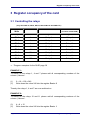
1
General information about the card ........................................5
1.1
Introduction .................................................................................................. 5
1.1.1 Our experience is your profit.................................................................................................. 5
1.1.2 Changes in this manual and Software updates ..................................................................... 5
1.1
Scope of supply ........................................................................................... 6
1.1
Card information .......................................................................................... 7
1.1.1 General information ............................................................................................................... 7
1.1.2 Operational area .................................................................................................................... 7
1.1.3 Functionality........................................................................................................................... 8
1.1
2
Technical Data ............................................................................................. 9
Installation procedures ..........................................................10
2.1
System requirements ................................................................................. 10
2.1
Safety precautions ..................................................................................... 10
2.1
Installing the board..................................................................................... 11
2.1
Card survey................................................................................................ 12
2.1.1 View for maximum component part assembly..................................................................... 12
2.1.2 Occupancy of the 37 pol. D-Sub connectors ....................................................................... 13
2.1.3 Occupancy of the Optocoupler connectors.......................................................................... 13
2.1.4 Occupancy of the TTL I/O.................................................................................................... 14
2.1
Technical data of relays ............................................................................. 15
2.1
Technical data of the Optocoupler ............................................................. 16
2.1.1 Input switching of the Optocouplers..................................................................................... 16
3
4
Register occupancy of the card.............................................18
3.1
Controlling the relays ................................................................................. 18
3.1
Reading of the Optocoupler input .............................................................. 20
Software Installation...............................................................22
4.1
What is the QLIB........................................................................................ 22
4.1
General information about the QLIB .......................................................... 22
4.1
Construction of the QLIB............................................................................ 23
4.1
Software- / QLIB- installation ..................................................................... 24
4.1.1 Installing the QLIB, sources and application programs ....................................................... 24
4.1
Supported compiler and operating systems ............................................... 25
4.1.1 QLIB supported operating systems ..................................................................................... 25
4.5
Program examples for the QLIB unter C.................................................... 26
4.5.1 Controlling the Optocouplers ............................................................................................... 26
4.5.2 Controlling the relays ........................................................................................................... 27
4.5.3 Controlling the TTL-I/O ........................................................................................................ 28
4.6
Controlling the card under Dos .................................................................. 29
4.6.1 Controlling the Optocouplers ............................................................................................... 29
4.6.2 Controlling the relays ........................................................................................................... 30
4.6.3 Controlling the TTL-I/O ........................................................................................................ 31
5
Annex ......................................................................................32
5.1
Frequently asked questions ....................................................................... 32
5.1.1 General information ............................................................................................................. 32
5.1.2 Running the card under Dos ............................................................................................... 32
5.1.3 Running the card under Windows 98/95.............................................................................. 35
5.1.4 Running the card under Windows 2000/NT......................................................................... 36
5.1
Page 4
Consultation and Help................................................................................ 38
General information about the card
1 General information about the card
1.1 Introduction
Congratulations! You’ve bought a QUANCOM measuring technique card. You are
now the proud owner of a modern measuring- and steering card which shows the
newest update of technology and whose attributes and functions are able to compete
with every other instrument and even outdoes them. The following special attributes
are included:
Resistance of the card
•
Only those components, which are available in Germany, are used
•
Diverse example programs in different programming languages
•
Driver support by Windows 2000, NT and 98/95 with the QLIB
1.1.1 Our experience is your profit
We from QUANCOM are specialists for the development of hard- and software. Our
experience ranges from impulse recording of web-machines by means of
temperature-measurement in nuclear power stations, to product data banks or the
time recording under LOTUS Notes.
1.1.2 Changes in this manual and Software updates
QUANCOM - products are distinguished by their constant further development. You
can see all the actual information of the changes in the README-file on the
installation disk or CD. You can always get more information and free software
updates on our internet website.
(WWW.QUANCOM.DE)
OPTOREL16,OPTORELTTL
Page 19
General information about the card
1.1 Scope of supply
•
•
•
Measuring technical card
User’s manual
QUANCOM measuring technical –CD
If a component is missing please contact your dealer. QUANCOM reserves the right
to change the extent of delivery without a preliminary announcement.
Page 6
General information about the card
General information about the card
1.1 Card information
1.1.1
General information
With our TTL-, Optoccoupler- and Relay cards you can switch extern circuits from
your PC or make a recording of switching proceedings in your PC.
The in- and outputs are controlled by software. Every relay has two connections, so
that voltages with different potentials as well as with alternating voltages can be
switched.
The Optocouplers function as Opto-inputs, consequently they can only record direct
current activity. In return, they are distinguished by a high switching speed and a
relative high voltage field (chapter 1.3 “Technical data”)
TTL- wires work as in- and outputs, but they can also work bi-directional and thus
they can record data and control extern devices respectively.
1.1.2
Operational area
QUANCOM TTL-cards are suited for triggering or for seizing the switching operation
of digital circuit.
QUANCOM Optocoupler- cards are utilised where a galvanic separation of two
circuits is clever or necessary (for example, Control- and Efficiency-component or for
the data transfer over long distances to avoid defects). Without special drivers you
can exclusively set them in for low voltage charge. Optocoupler-cards seize outer
switching events fast and precise.
QUANCOM relay-cards are best utilised for power-switching. They are very flexible
in their choice of the used voltages and they can also be charged with currents of 1A
or more.
OPTOREL16,OPTORELTTL
Page 19
General information about the card
1.1.3
Functionality
Our TTL-, Optocoupler- and Relay-cards are universal digital I/O-cards. With a
maximum of 16 DIL – Reed relays, 24 TTL-I/O channels and 16 Optocouplerinputs, it is suitable for many industrial jobs. All relays and Optocouplers are, among
each other and to the PC, galvanically isolated.
The Optocoupler have separated ground wires and are available on the card via a 16
pole tub connector. The 24 TTL-I/O are accessible on a 26-pole tub connector. The
relay contacts are accessible via a 37-pole D-Sub socket. Additionally to the
switching contacts at the D-Sub socket, there are GND, +5V, +12V, -12V, with
100mA available.
The relays are addressed by a simple Port-Out command. For the function control
the status of the relays is shown by LED’s. With the Port-In commands you can read
the signals into the Optocoupler. Accessing (read and write) the three ports of the
8255 takes place the same way.
Page 8
General information about the card
General information about the card
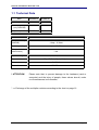
1.1 Technical Data
Karte
OPTOREL16
OPTORELTTL
Quantity TTLI/O
-
24
Switching-relays
(only Rel8/UM)
16
16
OptocouplerIN
16
8
Technical data
Relays (all except
Rel8/UM)
1 Amp / 15 Watt
Switching voltage
Up to 30V DC
Relay switch time
(with bounce)
1 ms
Opto-In-voltage
5, 12, 18, 30V *
Connectors
37.pol D-Sub, 26pol., 2*16pol.
Temperature range
5...50° C
Dimension
! ATTENTION !
158*97mm
Please note that, to prevent damage to the hardware (card or
computer) and the injury of people, these values should, under
no circumstances, be exceeded,.
* => Exchange of the multiplier resistors according to the chart on page 16
OPTOREL16,OPTORELTTL
Page 19
Installation procedures
2 Installation procedures
2.1 System requirements
•
Personal computer: The QUANCOM boards are
assigned to operate in IBM-AT compatible computers
with 80X86 or compatible. (i.e. 80386 / 80486 /
Pentium )
•
Bus: Your computer must have the corresponding bus. (PCI / ISA)
2.1 Safety precautions
For the sake of your security and of a safe function of your new QUANCOM board
mind the following advice:
•
Before opening the computer please unplug it.
•
Computer motherboards and components contain very delicate integrated circuit
(IC) chips. To protect them against damage from static electricity, you must follow
some precautions whenever you work on your computer. Use a grounded wrist
strap before handling computer components. If you don’t have one, touch both of
your hands to a safely grounded object or to a metal object, such as the power
supply case.
•
Hold components by the edges and try not to touch the integrated circuit chips,
leads or circuitry.
•
Place components on a grounded anti-static pad or on the bag that came with the
component whenever the components are separated from the system.
! ATTENTION !
Page 10
Modifications, made at the device without express permission of
QUANCOM, lead to the loss
Installation procedures
Installation procedures
2.1 Installing the board
CAUTION:
1. Always turn the system power off and remove the power cord from the wall before installing or removing any device.
2. Always observe static electricity precautions.
See „Safety precautions“ in chapter Safety
precautions
1. Switch off the computer and the connected devices and unplug them.
Warning: Static electricity can destroy your computer and the board!
Discharge yourself as described in chapter 3.2 “Safety precautions“.
2. To open your PC you have to detach the four
safety screws on the back of the case with a
screw driver. Then you can pull the cover
forwards. If necessary you must remove
impeding cables.
3. The slots are positioned at the back side of
your computer. The back wall of unused slots is
covered by a small metal plates. Search for a
free slot, detach its holding screw and remove
the small metal plate belonging to it.
4. Position the extension card into a free slot. Pay attention that the card is set firmly
in the slot.
5. Fasten the board with the screw of the small metal plate on the back wall.
6. Close the cover of your computer. Cables, that you detached during the installation, should now be reconnected.
7. Connect the cable of the board into the slot belonging to it.
OPTOREL16,OPTORELTTL
Page 19
Installation procedures
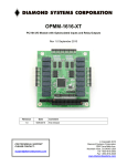
2.1 Card survey
2.1.1
View for maximum component part assembly
Advice: first block relays 0-7 / second block relays 8-15
lighting when the relays are switched on!
1
8
9
16
relays 0..7
37 pol. D-Sub slot
ispLSI 1016
Treiber
Oszillator
R-Network 2
ON
Opto 8..15
1
2
3
4
SW1
JP3
TTl-I/O 0..23
Treiber
Opto 8..15
R-Network 1
Opto 0..7
Opto 0..7
Relays 8..15
8255
JP2
JP1
GAL20V8B
JP 1
On
On
Timeout time 800ms
On
Off
Timeout time 200ms
Off
On
Timeout time 50ms
SW3
Function
on
Timeout-Watchdog
1D0*
2B0
300
310
330
3B0
3E0
Activated
on
IRQ at Timeout
off
IRQ at 0->1 on Opto0
Page 12
IRQ 5
Function
IRQ 4
SW4
JP 2
IRQ 3
Timeout-Watchdog
Deactivated
IRQ 2
off
IRQ 15
Timeout time 1,5s
IRQ 14
Off
IRQ 12
Off
IRQ 11
Function
IRQ 7
SW2
IRQ 10
SW1
Installation procedures
Installation procedures
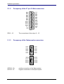
2.1.2
Occupancy of the 37 pol. D-Sub connectors
REL0
REL1
REL2
REL3
REL4
REL5
REL6
REL7
REL8
REL9
REL10
REL11
REL12
REL13
REL14
REL15
N.C.
VCC
+12V
REL0 - 15:
2.1.3
1
2
3
4
5
6
7
8
9
10
11
12
13
14
15
16
17
18
19
20
21
22
23
24
25
26
27
28
29
30
31
32
33
34
35
36
37
REL0
REL1
REL2
REL3
REL4
REL5
REL6
REL7
REL8
REL9
REL10
REL11
REL12
REL13
REL14
REL15
GND
-12V
The connections of the relays 0 – 15
Occupancy of the Optocoupler connectors
1
2
OPTO0+
OPTO1+
OPTO2+
OPTO3+
OPTO4+
OPTO5+
OPTO6+
OPTO7+
OPT O8+
OPT O9+
OPT O10+
OPT O11+
OPT O12+
OPT O13+
OPT O14+
OPT O15+
OPTO0..15+:
OPTO0..15-:
OPTO0OPTO1OPTO2OPTO3OPTO4OPTO5OPTO6OPTO715
16
1
2
15
16
OPT O8OPT O9OPT O10OPT O11OPT O12OPT O13OPT O14OPT O15-
positive connection of the Optocouplers
negative connection of the Optocouplers
OPTOREL16,OPTORELTTL
Page 19
Installation procedures
2.1.4
Occupancy of the TTL I/O
PA0
PA2
PA4
PA6
PB0
PB2
PB4
PB6
PC0
PC2
PC4
PC6
GND
Page 14
1
2
25
26
PA1
PA3
PA5
PA7
PB1
PB3
PB5
PB7
PC1
PC3
PC5
PC7
+5V
Installation procedures
Installation procedures
2.1 Technical data of relays
Maximum currency
Switchable voltage
Relays switching time (with bounce)
: 1Ampere / 15Watt
: 30V DC
: 1ms
Output switching of relays
Verbraucher
Karte
Rel
X
Einschaltrelais
Rel
OPTOREL16,OPTORELTTL
Quelle
X
Page 19
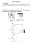
Installation procedures
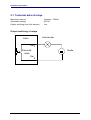
2.1 Technical data of the Optocoupler
Maximum Input voltage
Minimum Input currency
2.1.1
: 5, 12, 18, 30V (depending on resistance placement)
: 10mA
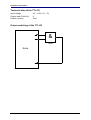
Input switching of the Optocouplers
connector
Input signal
at the driver on
the card
card
input
+
2,2k
Opto coupler
Power source
Input voltage
Page 16
Resistance network
5V
220Ω
12V
1kΩ
18V
1,5kΩ
24V
2,2kΩ
Installation procedures
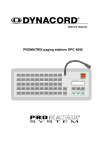
Installation procedures
Technical data of the TTL-I/O
Input voltage
Output load (FAN-Out)
Output currency
: 0V – 0.8V / 2V – 5V
:5
: 5mA
Output switching of the TTL-I/O
&
7400
Karte
OPTOREL16,OPTORELTTL
Page 19
Register occupancy of the card
3 Register occupancy of the card
3.1 Controlling the relays
( only OPTOREL16, REL8, REL16, REL8/UM and OPTORELTTL)
Valence
Access: Port +0
Write
Access: Port +1
(not REL8 and REL8/UM)
Output
Relays 0-7
Relays 8-15
Bit 0
1
Relay 0
Relay 8
Bit 1
2
Relay 1
Relay 9
Bit 2
4
Relay 2
Relay 10
Bit 3
8
Relay 3
Relay 11
Bit 4
16
Relay 4
Relay 12
Bit 5
32
Relay 5
Relay 13
Bit 6
64
Relay 6
Relay 14
Bit 7
128
Relay 7
Relay 15
Port is the I/O-basis address of the card
⇒ “Program examples for the QLIB” page 26
EXAMPLE 1.:
To switch on the relays 1, 4 and 7 please add all corresponding numbers of the
column „Valence“.
(1)
(2)
2 + 16 + 128 = 246
Write down the value 246 into the register Port + 0
Thereby the relays 1, 4 and 7 are now switched on.
EXAMPLE 2.:
To switch on the relays 10 and 11 please add all corresponding numbers of the
column „Valence“.
(3)
(6)
4 + 8 = 12
Write down the value 246 into the register Port + 1
Page 18
Register occupancy of the card
Register occupancy of the card
Thereby the relays 10 and 11 are now switched on.
TIP.:
During every writing cycle 8 relays are always switched on or off. To switch a single
relay on or off, and thereby not changing the switching condition of the remaining
relays, you can note the switching condition in a variable. Over a logic „OR“ or a
„AND“-knotting the switching is easy realisable.
EXAMPLE 3.:
Assumption: In example 1, we described that the relays 1, 4 and 7 were switched on.
Now the relay 0 should additionally be switched on. The relay 0 has the valence 1.
Therefore the value 246 is „OR“-knotted with 1. In C or C++ the operator “&” is
equivalent to the disjunction „OR“.
(4)
(5)
(6)
The value 246 is stored into a variable.
246 OR 1 = 247
Write down the value 247 into the register Port + 0
Thereby the relays 0, 1, 4 and 7 are switched on.
EXAMPLE 4.:
Assumption: In example 3, we described that the relays 0, 1, 4 and 7 were switched
on. Now the relay 7 should additionally be switched off. The relay 7 has the valence
128. Therefore, the value 247 is „AND“-knotted with the complement of 128. In C or
C++ the operator “&” is equivalent to the conjunction „AND“ and the operator “~” to
the negation „NOT“.
(7)
(8)
(9)
The value 247 is stored into a variable.
247 AND (NOT 128) = 119
Write down the value 119 into the register Port + 0
There by the relays 0, 1 and 4 are switched on.
Register occupancy of the card
3.1 Reading of the Optocoupler input
Reading
Valence
Input
Access: Port +4
Access: Port +5
OPTOI 0-7
OPTOI 8-15
Bit 0
1
OPTO0
OPTO8
Bit 1
2
OPTO1
OPTO9
Bit 2
4
OPTO2
OPTO10
Bit 3
8
OPTO3
OPTO11
Bit 4
16
OPTO4
OPTO12
Bit 5
32
OPTO5
OPTO13
Bit 6
64
OPTO6
OPTO14
Bit 7
128
OPTO7
OPTO15
Port is the I/O-basis address of the card
Please notice:
If one bit is set on high (‚1‘), then the respective Optocoupler-input is not active, if
one bit is set on low (‚0‘), then you have a voltage at the respective Optocouplerinput.
⇒ “Program examples for the QLIB” page 26
In every reading cycle, 8 inputs are read at the same time. To keep the condition of
an input this must be dimensioned from the read value.
EXAMPLE 1.:
To read the condition of an optocoupler input OPTO5, proceed as follows:
(10)
(2)
Read the register Port + 0 into a variable
Variable AND 32 = OPTO5
If the value in OPTO5 is unequal 0, the Optocoupler in/out is not activated. That
means that it has no power. In C or C++ the operator “&” is equivalent to the
conjunction „AND“.
Page 20
Register occupancy of the card
Register occupancy of the card
EXAMPLE 2.:
To read the condition of the Optocoupler input OPTO9, proceed as follows:
(11)
(2)
Read of the register Port + 1 into a variable
variable AND 2 = OPTO9
If the value in OPTO9 is unequal 0 the Optocoupler in/out is not activated. That
means that it has no power. In C or C++ the operator “&” is equivalent to the
conjunction „AND“.
Software Installation
4 Software Installation
4.1 What is the QLIB
The QLIB, a short form for QUANCOM Library, offers the possibility, to address all
QUANCOM-cards with the operating systems Windows 2000/NT and 98/95 and the
programming languages C/C++/Delphi/Visual Basic. It is delivered together with all
QUANCOM-cards and allows the user, with the help of simple commands, to
integrate the QLIB into their applications.
4.1 General information about the QLIB
Independent operating system programming
All QUANCOM-cards are programmed independent of operating systems. The QLIB
(QUANCOM Library) offers you the possibility, to respond to all QUANCOM-cards
with the operating systems Windows 2000/NT and 98/95 and the programming
languages C/C++/Delphi/Visual Basic with just a few commands.
Programming, independent of program language
It doesn’t matter, if a application is programmed under C, C++, Delphi, Visual Basic,
HP VEE, or LabView. The QLIB supports up to 16 QUANCOM-at once in a computer
and it is not of importance, if all cards are of the same type or not.
SDK-Kit for programmers
This component is included in delivery. The Software Development Kit (SDK) offers
further tools, source code and examples, which are necessary for the installation of
the QLIB, to equip self programmed applications with the QLIB.
Page 22
Software Installation
Software Installation
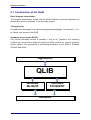
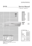
4.1 Construction of the QLIB
Block diagram interpretation
The diagram stated below shows how the QLIB builds the connection between the
applications and the Hardware or the operating system.
The application
An application developed in an optional programming language, for example C, C++
or Pascal, has access to the QLIB.
Hardware access under Win32s
Only limited Hardware access is possible, if any at all. Therefore, the operating
systems are not accessed directly through the QLIB, instead, by special operating
system drivers. This guarantees a conforming integration of the QLIB in Windows
2000/NT and 98/95.
Applikation
QLIB
Windows
Me/98/95
Windows
XP/2000/NT
Hardware
Software Installation
4.1 Software- / QLIB- installation
4.1.1
Installing the QLIB, sources and application programs
1. Please insert the QUANCOM-measuring technics-CD.
If Windows starts the CD-Rom automatically continue with point 5.
2. Please click the Start button. (on the left/bottom in the Task-menu)
3. Please choose Perform.
4. Please perform the following command:
D:\Autorun
(If D is not the drive-letter of your CD-Rom drive, replace D with the right letter.)
5. Please choose the product name of the card and follow the installation
instructions.
Page 24
Software Installation
Software Installation
4.1 Supported compiler and operating systems
4.1.1
QLIB supported operating systems
The QLIB, which stands for QUANCOM Driver LIBrary, was developed with the
target to allow the simple programming of all our data acquisition products under
various operating systems. So it is easy to write an application that runs under the
operating systems Windows Me/98/95 and Windows XP/2000/NT 4.0. This driver
interface is not limited to PC boards or other I/O adapters but is also targeted
towards supporting the next product generations currently being developed. The
used functions and parameters are the same for all operating systems.
Supported operating systems:
• Microsoft Windows XP/2000/NT 4.0
• Microsoft Windows Me / 98 / 95
Supported compilers:
C / C++
• Borland C++ 3.1, 4.x, 5.x
• Microsoft® Visual C++ 1.x, 2.x, 4.x, 5.x
Pascal
• Borland Turbo Pascal
Delphi
• Borland Delphi
Basic
• Microsoft® Visual Basic 3.x, 4.x, 5.x; 6.x
Graphical Programming Language
• HP VEE from Hewlett-Packard
• LabView® of National Instruments
Software Installation
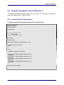
4.5 Program examples for the QLIB unter C
The following program examples show you, how easy it is to develop a program to
control the cards under C with the QLIB.
4.5.1 Controlling the Optocouplers
Program example for the Optocoupler with the QLIB under C
#include <windows.h>
#include <stdio.h>
#include <conio.h>
#include "qlib.h"
/*=====================
main program
======================*/
void main ()
{
ULONG handle;
if ((handle=QAPIExtOpenCard(handle,0L)) == 0L)
{
printf("card could’n be open\n");
return;
}
for (;;)
{
if (kbhit()!=0 && getch()==27) break;
printf("%04lx\n",QAPIExtReadDI16(handle,0L,0L));
Sleep(500);
printf("%04lx\n",QAPIExtReadDI16(handle,0L,0L));
Sleep(500);
printf("%04lx\n",QAPIExtReadDI16(handle,0L,0L));
Sleep(500);
printf("%04lx\n",QAPIExtReadDI16(handle,0L,0L));
Sleep(500);
}
QAPIExtCloseCard(handle);
}
Page 26
Software Installation
Software Installation
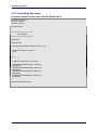
4.5.2 Controlling the relays
Program example for the relays with the QLIB under C
#include <windows.h>
#include <stdio.h>
#include <conio.h>
#include "qlib.h"
/*=====================
main program
======================*/
void main ()
{
ULONG rel16;
if ((rel16=QAPIExtOpenCard(REL16,0L)) == 0L)
{
printf("card could’n be open\n");
return;
}
for (;;)
{
if (kbhit()!=0 && getch()==27) break;
QAPIExtWriteDO8(handle,0L,0x00L,0L);
Sleep(500);
QAPIExtWriteDO8(handle,0L,0xFFL,0L);
Sleep(500);
QAPIExtWriteDO8(handle,0L,0x55L,0L);
Sleep(500);
QAPIExtWriteDO8(handle,0L,0xAAL,0L);
Sleep(500);
}
QAPIExtCloseCard(handle);
}
Software Installation
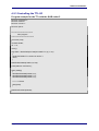
4.5.3 Controlling the TTL-I/O
Program example for the TTL with the QLIB under C
#include <windows.h>
#include <stdio.h>
#include <conio.h>
#include "qlib.h"
/*=====================
main program
======================*/
void main (void)
{
ULONG handle;
int i = 0;
clrscr();
if ((handle = QAPIExtOpenCard(OPTORELTTL,0)) == 0L)
{
printf("OPTORELTTL could’n be open\n");
return;
}
QAPIExtWrite8255(handle,0,3,128);
printf("Abbruch mit ESC\n");
while (!kbhit())
{
QAPIExtWrite8255(handle,0,0,i);
QAPIExtWrite8255(handle,0,1,i);
QAPIExtWrite8255(handle,0,2,i);
i = (i + 1) & 255;
Sleep(500);
}
QAPIExtCloseCard(handle);
}
Page 28
Software Installation
Software Installation
4.6 Controlling the card under Dos
The following program examples show you, how easy it is to develop a program for
the QUANCOM-cards.
4.6.1 Controlling the Optocouplers
Program example for the Optocoupler under C
#include <stdio.h>
void main()
{
unsigned int port;
int i;
long int j;
unsigned int wert;
port=0x1d0;
if(port==0) exit(0);
while(!kbhit()) {
for(i=0;i<16;++i) {
wert=1<<i;
for(j=0;j!=200000;++j);
printf("%x %x \n",inp(port+4),inp(port+5));
}
}
}
Software Installation
4.6.2 Controlling the relays
Program example for the relays under C
#include <stdio.h>
void main()
{
unsigned long ret;
unsigned int port;
int i;
long int j;
unsigned int value;
port=0x1d0;
if(port==0) exit(0);
while(!kbhit()) {
for(i=0;i<16;++i) {
wert=1<<i;
for(j=0;j!=200000;++j);
outp(port,value&0xff);
outp(port+1,(value>>8)&0xff);
}
}
getch();
}
Page 30
Software Installation
4.6.3 Controlling the TTL-I/O
Program example for the TTL under C
#define p8255A port+0xc
#define p8255B port+0xd
#define p8255C port+0xe
#define p8255CMD port+0xf
#include <stdio.h>
void main()
{
unsigned int port;
int i;
long int j;
unsigned int wert;
port=0x1d0;
if(port==0) exit(0);
/*TTL-I/O*/
outp(p8255CMD,128);
/*8255 auf Ausgabe*/
while(!kbhit()) {
for(i=0;i<8;++i) {
wert=1<<i;
outp(p8255A,wert&0xff);
for(j=0;j!=200000;++j);
printf("Port A=%2x Port B=%2x Port C=%2x\n",inp(p8255A),inp(p8255B),inp(p8255C));
}
outp(p8255A,0);
for(i=0;i<8;++i) {
wert=1<<i;
outp(p8255B,wert&0xff);
for(j=0;j!=200000;++j);
printf("Port A=%2x Port B=%2x Port C=%2x\n",inp(p8255A),inp(p8255B),inp(p8255C));
}
outp(p8255B,0);
for(i=0;i<8;++i) {
wert=1<<i;
outp(p8255C,wert&0xff);
for(j=0;j!=200000;++j);
printf("Port A=%2x Port B=%2x Port C=%2x\n",inp(p8255A),inp(p8255B),inp(p8255C));
}
outp(p8255C,0);
}
}
Annex
5 Annex
5.1 Frequently asked questions
5.1.1
General information
Do you have problems with the Net work cards?
Yes, according to how you have addressed the port of your QUANCOM or networkcard you could become resource-conflicts. Either you change the Port-address of the
QUANCOM-card or of that of the Network-card.
I have a Network card inside my computer which is not addressable after the
installation of the QUANCOM-card! What can I do?
Change the Port-address of the QUANCOM-card or the Port-address of the Network
card to remove the problem.
You have problems with the soundcard?
Yes, according to how you have addressed the port of your QUANCOM or
soundcard, you could become resource-conflicts. Either you change the Port-address
of the QUANCOM-card or that of the Network card.
5.1.2
Running the card under Dos
Can I use the card in connection with a Store-Manager?
(QEMM 386,EMM386)
Yes, but the use of a Store-Manager can make your computer or the software slower.
Page 32
Annex
Frequently asked questions
The card is not responding under DOS with the direct-IO commands, what is
the reason or what can I do?
1) Problems with the Optocoupler-input
- Port conflict: 2 cards are using the same IO-Basis-address, change the Basisaddress of your QUANCOM-card.
- Wrong IO-Basis-address in the program. Check if the Basis-address stated in your
program is corresponding to the jumped Basis-address on the card.
- The voltage, at the Optocoupler-input, is too low to control the Optocouplers.
Choose a higher voltage or change the multiplier under consideration of the technical
specification of this card.
- Examine, if the Optocouplers are switched correctly.
- The multipliers were damaged by a too high Input-voltage.
- The Optocouplers were damaged by a to high Input-voltage.
2) Problems with the Relays-output
- Port conflict: 2 cards are using the same IO-Basis-address. Change the Basisaddress of your QUANCOM-card.
- Wrong IO-Basis-address in the program. Check if the Basis-address stated in your
program coincides with the jumped Basis-address on the card.
- Check if the relays are switched correctly.
3) Problems with the TTL- In/Output
- Port conflict, 2 cards are using the same IO-Basis-address, change the Basisaddress of your QUANCOM-card.
- Wrong IO-Basis-address in the program. Check if the Basis-address stated in your
program is coincides with the jumped Basis-address on the card.
- Check if the TTL-In/Output are switched correctly.
- Check if the load is too high. They should not exceed XX .
Annex
- Check the voltage at the input. If this is set too high, then the inputs could be
damaged.
- It is possible that the inputs were damaged by static electricity.
- Check the input-switching for possible faults, switched polarity or the like.
Page 34
Annex
Frequently asked questions
5.1.3
Running the card under Windows 98/95
Why is the card-dialogue under the QLIB empty?
- There is no QUANCOM-PCI-card in the system.
- There are no drivers for a QUANCOM-card installed.
After installation I get the message “QLIBNDRV.SYS not found“. What can I
do?
- If you use a QUANCOM-ISA-card, check if the drivers for the QUANCOM-card are
installed.
- Check if the driver was installed correctly, and if it was configured correctly. (System
control => Devices)
After Software-Installation I get the message „Direct-IO interface can not be
initialised qmulti32.dll could not be initialised“. What can I do?
- If you use a QUANCOM-ISA-card, check if the drivers for the QUANCOM-card are
installed.
- Check if the driver was installed correctly, and if it was configured correctly. (System
control => Devices)
Why does QAPIExtOpenCard give the return value 0 back, although the card is
installed?
- Check if the driver is installed.
- The card is not configured. (System control => QLIB / watch QLIB-documentation)
Why do I get the message "Driver QLIBNdrv.SYS could not be loaded” ?
-There was no driver for a ISA-card installed.
- Installation failed, because QLIB was installed without Administrator rights
-The driver for the QUANCOM-card was not loaded. (System control => Devices)
- QLIB was installed on a Network device.
Annex
5.1.4
Running the card under Windows 2000/NT
Why is the card-dialogue under the QLIB empty?
- There is no QUANCOM-PCI-card in the system.
- There are no drivers for a QUANCOM-card installed.
Must the QLIB be installed with Administrator rights?
Yes, the QLIB must be installed with Administrator rights.
Why do I get the message “Driver could not be installed” during the
installation?
- Installation was made without Administrator rights.
Why do I get the message "driver QLIBNdrv.SYS could not be loaded“?
- The driver, “QLIBNDRV”, is not listed in the list under „System control => Devices“,
or is not booked as “started” there.
- Driver installation failed because the QLIB was not installed with Administrator
rights.
- QLIB-Software was installed on a network drive.
How can I install the driver QLIBNDRV.SYS manually?
Sometimes it happens, that the file QLIBNDRV.SYS is not installed correctly on the
system. To install the driver manually please follow these instructions:
1) In the QLIB- register Tools exists the tool “instdrv.exe”. With this tool you can
install/uninstall the driver manually.
2) Please call this tool up with the following command: instdrv qlibndrv
d:\verzeichnisname\qlibndrv.sys, whereby you replace d:\verzeichnisname\ with
the drive and the file, where the driver file “qlibndrv.sys” lies on your system.
3) Go under “ System control => Devices ” and change the Start type on “automatic”,
then click on the Start button. After that, you may have to restart your computer, so
that the changes become effective.
Page 36
Annex
Frequently asked questions
Why must I restart the driver after every restart of the computer?
The starting type of the driver is set on manual. You can change the settings to
„automatic“.
Newest Software versions
Where can I get the newest drivers/software for the QUANCOM-cards?
You can find the newest drivers on our Internet WWW-sides.
http://www.quancom.de/download
Annex
5.1 Consultation and Help
You need help?
If you don’t know how to
go
on
during
the
installation or operation of your QUANCOM
board please first consult this user’s guide.
! Tip !
In the chapter A.1 „Frequently asked
questions“ a lot of questions are answered.
They may help to solve the problems. On the
QUANCOM installation CD you can find a
ASCII – Text – file README.TXT, which
include changes made after printing of this
user’s manual.
! IMPORTANT !
If you have further questions please contact
our support team and have the following
information handy:
• Exact type of the board.
• Version of the driver
• Version of the QLIB
• Operating system, Hardware equipment
and Bus - System
• Name and Version of the program, where
the error is reported.
1.
• A detailed failure description. To
make sure, please try to reproduce the
failure, describe it as exact as possible, and
which steps led to this failure.
Who can you contact?
The QUANCOM Internet side
WWW.QUANCOM.DE
Per Fax
0 22 36 / 89 92 - 49
Per e-mail:
Page 38
Annex
Consultation and Help
[email protected]
In written form:
QUANCOM INFORMATIONSSYSTEME
GmbH
In der Flecht 14
50389 Wesseling
If you need urgent help call:
QUANCOM Hotline Germany
0 22 36 / 89 92 - 20
Monday-Thursday
from 9:00 to 18:00
Friday
from 9:00 to 17:00
Newest drivers
You can find the newest Version of
QUANCOM software on our internet website
http://www.quancom.de. You can also find a
lot of information and „Frequently asked
questions (FAQ’s)”. Before you contact the
QUANCOM support, please check if you are
using the newest software version of the
QUANCOM software.
Annex
Repairing?
If you are not sure whether your QUANCOM
board is defective please call the QUANCOM
Hotline:
Tel.: 0 22 36 / 89 92 – 20
Call before you send us the QUANCOM
board to be repaired.
If you send us your QUANCOM board,
please use original package or any other
suitable package, to protect the contents
against transport damage. You also need to
send us a copy of the original bill and the
RMA number.
You can shorten the repair time by sending
us an exact failure description, so that a
faster failure search is possible. Send your
QUANCOM board directly to the service
department of QUANCOM Informationssysteme GmbH.
Page 40
Annex
registered trade-mark:
Windows/386 is trademark of Microsoft
XT and PS/2 are trademarks of IBM, OS/2 and AT are registered to the International Business
Machines Corporation.
National Instruments, LabVIEW are registered trademark of National Instruments Corporation
MS, MS-DOS, Microsoft, Visual Basic, Windows, Windows NT are registered trademark
of Microsoft Corporation
By other product- and company names, that are mentioned in this manual, it may deal with trademarks
of the respective owners.