1
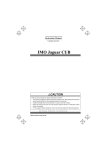
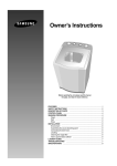
FILE No.
Service Manual
CO2 Incubator
MCO-5AC
SM9910037
Contents
Page
㩷㩷㩷㩷㩷㩷㩷㩷㩷㩷㩷㩷㩷㩷㩷㩷㩷㩷㩷㩷㩷㩷㩷㩷㩷㩷㩷㩷㩷㩷㩷㩷㩷㩷㩷㩷㩷㩷㩷㩷㩷㩷㩷㩷㩷㩷㩷㩷㩷㩷㩷㩷㩷
Features
1
Structural specification
2
Performance specification
3
Control specification
4
Dimensions
5
Electrical parts
7
Temperature calibration
CO2 Calibration
8
CO2 zero adjustment
9
Control specification
10
Wiring diagram
21
Circuit diagram
Components on P.C.B.
22
23
Connection on PCB
24
CO2 gas circuit
Instructions on replacing CO2 sensor and main P.C.B.
25
Prevention of contamination
27
Specification of sensor
28
Parts layout
Test data
29
31
UV lamp (MCO-18UVS2) installation procedure
35
How to replace water level sensor
Automatic gas switcher (MCO-5GC) mounting procedure
39
Stacked module
43
Instruction Manual
44
9
26
40
Effective models
This service manual is effective following models.
Model name
MCO-5AC
㩷
Model code
823 282 51
823 282 52
823 282 53
823 282 54
Voltage and Frequency
110-120V
60Hz
220V
50Hz
220V
60Hz
220-240V
50Hz
Features
1. Easy operation & smaller installation space
zThis small sized cabinet can be stacked. (548mm of its depth)
zUsable height (only 1704mm height) even if stacked 3 units.
zSelectable right or left-hand door.
(Please consult with your service representative.)
zAir-jacket type is suitable for the maintenance.
zControl panel is fitted on the outer door surface and it has a wide digital display
and a large keypad.
zInside chamber wall made by stainless steel and its corner made rounded type,
cleaning easier.
2. Internal temperature & internal humidity recovery characteristics
zOriginal Direct Heat & Air (DHA) jacket system
3. Anti-bacteria SUS
zInside chamber (except for humidifying pan) material is made by anti-bacteria
SUS.
4. A new ROM installed
zA new ROM version installed to set Communication system optionally.
5. Validation
zDisplay Zero Adjustment and Span Adjustment can be operated on the control
panel.
Note ; Model name
M
CO
–
5
A
C
C: Copper alloy anti-bacteria stainless steel
A: Air jacket
5: Chamber capacity (50L)
CO: CO 2 Incubator
M: Medical equipment
1
Dimensions
5
6
14.
Ring back
When the apparatus falls into alarming, BZ key should not be pressed by someone to be
buzzer/remote alarm action inoperative.
Function:
1. Buzzer comes back after Ring Back setting time was passed even if buzzer is
stopped sounding by pressing BZ key.
2. Remote alarm action is not cancelled by pressing BZ key.
3. Alarm indication on the control panel is keep displaying.
<Alarm operation specification>
Auto-recovery 30min.
Auto-recovery inoperative
(F25=030)
(F25=000)
Alarming
zPress BZ key to solely stop buzzer sounding.
zRemote alarm and alarm on the control panel keeps activating.
When recovery to normal
zAlarm stand-by
zWhen alarm comes back again, buzzer and remote alarm are
operative, alarm can be displayed on the control panel.
When
alarm
keeps Buzzer recovers after 30minutes Buzzer does not sound unless
activating after the setting passed since BZ key was alarm keeps activating even
time has passed
pressed.
though BZ key is pressed.
Remote alarm and alarm on
control
panel
are
keep
activating.
Status
<SV and buzzer recovery time>
SV
Buzzer recovery time after buzzer is stopped
sounding by pressing BZ key.
000
Buzzer does not sound
010
Approx. 10min.
020
Approx. 20min.
030
Approx. 30min.
040
Approx. 40min.
050
Approx. 50min.
060
Approx. 60min.
<Special mode>
Remote alarm action is interlocked with buzzer by function code setting.
The function code must not be opened to prevent remote alarm action changed easily.
Auto recovery
(F25=030)
Buzzer setting
Not auto recovered
(F25=000)
SV
000 (initial setting)
001
Remote alarm action setting
Buzzer independent
Buzzer interlocked
(initial setting)
(F24=001)
(F24=000)
Buzzer auto recovered Buzzer auto recovered
Remote alarm keeps Remote alarm auto
activating
recovered
Buzzer is not auto Buzzer is not auto
recovered
recovered
Remote alarm keeps Remote alarm is not
activating
auto recovered
Remote alarm action
Not interlocked with buzzer
Interlocked with buzzer
19
Wiring Diagram
21
Circuit Diagram
22
Components on P.C.B.
23
CO2 gas circuit
CO2 valve
Filter
CO2 supplied
Sample port
Rear view
25
Parts Layout
Handle (removable)
Sample air outlet cap
Connecting port for CO2 gas pipe
29
Access port
CO2 valve
Filter
Connecting port for CO2 gas pipe
Access port
Fan motor
Remote alarm terminal
Main PCB
30
34
35
6. Replace the duct. Place the humidifying tray,
then cover the tray with the humidifying tray
cover as shown in Fig. 5
8. Remove a cap shown in Fig. 7.
By using 4 screws enclosed with this kit,
fix the ballast/glow assy as shown in Fig. 7.
Humidifying tray cover
⑤Ballast
Fig.5
③Screw
7. Replace the insulation into the UV lamp lead wire
hole with the wire passed through the cut on the
insulation. See Fig.6
Fig.6
36
Cap
④Glow assy
Fig.7
9. Connect each lead wire connector of ballast/glow assy, as shown in Fig. 8.
BLUE
Cover
GREEN
Connect after removing
the cover.
Fig.8
10. Attach the labels.
* For nameplate, use MCO-5AC(UV) label on MCO-5AC.
Fig.9
37
11. Set the UV lamp ON period through control panel
When using UV lamp option, it is needed to set the UV lamp ON period. Refer to the following
procedure.
Description of operation
Key
Indication after operation
operated
1
Turn the power switch ON.
The current chamber temperature is
displayed.
2
Press CAL key for 5 seconds.
3
By pressing
key and
key, set the figure to F01.
4
Press ENT key.
5
By pressing
key and
key, set the figure to 005 (5
minutes of ON period).
Press ENT key.
6
CAL
The left digit in the temperature indicator is
flashed.
F01
ENT
ENT
In CO2 density indicator,
"000" is displayed and the
right digit is flashed.
F01
000
F01
005
The setting of UV lamp ON time is
memorized and the current chamber
temperature is displayed.
<<NOTE>>
• The UV lamp ON time is settable between 0 to 30 minutes. However, it is recommended to set 5
minutes in general.
• The UV lamp ON time is settable between 0 to 30 minutes (000 to 030). The UV lamp is not
turned ON if the setting is 000.
• The UV lamp is turned off when the outer door is opened while the lamp is on. The lamp is
turned on for pre-set duration after the outer door is closed.
• The condensation in the chamber can be caused and/or the chamber temperature distribution can
be affected due to the heat from UV lamp when the setting of UV lamp ON time is longer than 5
minutes or the only the outer door is opened/closed repeatedly. In such case, the life of UV lamp
is shortened.
• In the procedure 2 above, pressing CAL key for 5 seconds causes the calibration mode. In this
mode, it is possible to calibrate the temperature and CO2 density, and miss operation of the key
may affect the basic performance of the unit. Take care of the key operation. Even if the key is
operated wrongly, the unit returns to the current value display mode automatically when no key is
operated for 90 seconds. In this case, the setting not entered by pressing ENT key is not
effective.
12. Check that the UV lamp is turned on.
Check the UV lamp is turned on by the following procedure:
Procedure
1
Open the outer door and push the door switch with the inner door is closed.
2
Check that the UV indicator on the control panel is on after a few seconds.
3
Check the visible blue light from the front side of the humidifying pan cover.
(Check the light with the inner door closed. Never look at the UV light directly.)
7FB6P104048000
38
HOW TO REPLACE WATER LEVEL SENSOR
1.Unplug the unit and check that power is not supplied
to the unit, then take the rear cover off.
2.Unfasten the connectors for lead wire and take out
the insulation for the lead wire hole.
3.Take out the duct from inside.
Fig.1
4.Unfasten the 2 screws to remove unit of water level
sensor and installation grommets for water level sensor.
5.replace water level sensor.
Note Be sure to set the water level sensor to the right
direction. (See Fig.3)
screw
6.Place back the water level sensor, Water sensor
installation grommet as before.
7.Place back the insulation material to the hole for the lead
Water level sensor
Installation grommet
wire.
Note Be careful for the length of lead wire for water level
Water level sensor
sensor inside the unit Length is connect 2nd binder
is located where it touches the water level sensor
Fig.2
grommet.
(See Fig.4)
3.Put the rear cover in place.
Fig.3 (front)
Sensing area
39
Fig.4
Setting procedure of Control panel.
When use MCO-5GC(the automatic switcher of CO 2 gas supply line),it is necessary to set the
MCO-5AC automatic gas switching mode according to the following procedures.
Description of operation
Key
operated
1
Turn the power switch ON.
2
Press CAL key for 5 seconds.
3
By pressing
key and
set the figure to F03.
4
Press ENT key.
5
By pressing
key and
set the figure to 384
6
Press ENT key.
7
Press CAL key for 5 seconds.
8
By pressing
key and
set the figure to F08
9
Press ENT key.
10
By pressing
key and
key,
set only the left digit figure to 1.
11
-
The current chamber temperature is
displayed.
CAL
The left digit in the temperature indicator
is flashed.
key,
F03
ENT
key,
In CO2 density indicator,
"000" is displayed and the F 0 3
right digit is flashed.
000
F03
384
ENT
The current chamber temperature is
displayed.
CAL
The left digit in the temperature indicator
is flashed.
key,
F08
ENT
NOTE:Don't change center
digit figure and right
digit figure.
Press ENT key.
Indication after operation
In CO2 density indicator,
"0**" is displayed and the F 0 8
right digit is flashed.
0**
F08
1**
"*" means "0" or "1".
ENT
41
Setting of MCO-5GC is finished.
The current chamber temperature is
displayed.
CO2 gas supply line indicator A is lighted.
Procedure for automatic gas switching operation check.
When the installation of MCO-5GC is completed, check the automatic gas switching operation
according to the following to the following procedures.
procedure
1
Stop the gas supply of cylinder A and use cylinder B only for CO2 gas supply.
2
Turn on the power switch of MCO-5AC and set 37decC and 0%.
Turn on CO2 gas supply line indicator with CO2 gas supply line switching key.
3
Wait for approx.1 minute until CO2 control is available.
(It takes about 1 minute until CO2 control is effective after power ON.)
4
Set the CO2 density to 5% and check CO2 inject lamp lights.
NOTE: CO2 inject lamp may not light depending on the temperature, humidity or
CO2 density in the chamber. In this case, set the CO2 density 1% or more
higher than the displayed value.
5
Check the E01(CO2 gas cylinder empty alarm) and buzzer turn on about
2-7minutes later from the CO2 inject lamp's turning on.
6
Check the CO2 gas density indicator reaches to the set value 5% and keep it
stably.
NOTE: CO2 density control is interrupted when automatic calibration of CO2 sensor
is activated and the decimal point of CO2 density indicator blinks.
7
This is the end of check procedure.
Press the buzzer key to disappear “E01” and select the cylinder A with CO2 gas
supply select key.
Set the CO2 density to 0% and open the door to release the CO2 gas completely.
After the chamber temperature and humidity are stable, set the CO2 density to
desired value.
Refer to the MCO-5AC instruction manual for usage of MCO-5GC
42
7FB6P104047000
Stacked module
This unit can be stacked by using the stacking kit. Following shows the procedure for stacking the unit.
Consult with a Sanyo representative or agent prior to stacking procedure as such work involves dangers.
WARNING
Select a level and sturdy floor having enough strength for installation of stacked module.
Never stack 4 or more units.
Take care not to drop or tip over the unit when stacking as this can cause injury or damage of the
unit.
1. Turn off the power switch and disconnect a plug of each unit.
2. The stacking plate A and B are contained in accessories bag.
Note: When stacking the unit, 2 stacking plates A and 2 stacking plates B are necessary.
3. Check that the lower unit is level.
4. Remove two caps at 2 locations on the top front of under unit, and apply the protective sticker enclosed
with the unit at each corner on the top of the lower unit to avoid scratches or damage(Fig.A).
5. Fix the stacking plate A at 2 locations on the top front of the lower unit by using 2 screws contained in
accessories bag.
6. Remove the front panel on the upper unit by unscrewing the 4 fixing screws and then disconnect the
wires and gas tube.
7. Stack the unit so that both units can be aligned straight. Also check the upper unit is level. If it is not
level, keep the unit even by adjusting the leveling legs.
8. Secure the upper unit with the stacking plate A and 2 screws contained in accessories bag.
9. Remove 2 screws on the above right and left on the rear side of the lower unit.
10. Remove 1 screw on the bottom right and left on the rear side of the upper unit.
11. Fix the stacking plate B at the right and left on the rear of the lower and upper unit with 3 screws
removed in step 9 and 10.
12. Replace the front panel on the upper unit after connecting the wires and gas tube.
13. Repeat procedures from step 3. when stake more.
14. Fix the stacked unit to the wall with 2 stacking plate B on the rear of the top unit and rope or chain.
Front panel
Stacking plate B
Stacking plate A
Protective sticker
Fig.A
43
<View from quarter rear side>