1
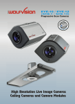
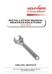
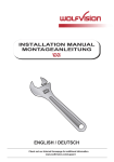
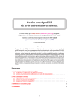
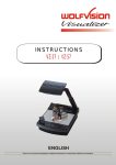
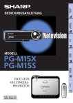
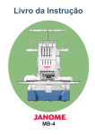
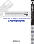
R
INSTALLATION MANUAL
MONTAGEANLEITUNG
VZ-C10
ENGLISH / DEUTSCH
English
Symbol Legend
This symbol is noted by safety instruction procedures where a High Risk of Personal Injury is present. Be sure
to read all directions very carefully and exersise extreme caution! Also be sure to follow proper health and saftey
rules in accordance with applicable local and federal laws.
Attention
G
Symbol is noted by instructions that require special attention in order to avoid possible Equipment Damage.
Attention
Warning
Saftey Procedures
The Ceiling Visualizer VZ-C10 is built with state-of-the-art technology and is safety engineered. Regardless of this, operational
risks may be present if proper safety procedures are not obeyed. It is essential that all safety and instruction procedures
are read and followed closely !
- Store all operation manuals in an easily accessible area !
- The unit should be installed or repaired by authorized and certified personnel only !
- Always follow safety and operational procedures when working with the unit !
- Respect all warning and operation signs !
- Security features must not be disabled or removed !
Preparation
1.) Inspect the unit for any transport damage. In the event that damage is found, call your WolfVision dealer immediately
and do not attempt installation of the VZ-C10 !
2.) Confirm that all parts and accessories are present.
G
Read through the entire Installation Manual before beginning installation !
Ceiling Preparation
Due to the diverse installation possibilities of our ceiling mounting bracket, WolfVision can only provide general installation
instructions.
Please study the following installation steps carefully. Should you encounter any problems (not covered in the installation
instructions), please contact your WolfVision representative for assistance.
Take special notice regarding the weight of the VZ-C10 Ceiling Visualizer and the potential for personal injury, as well as the
possibility for damage to the VZ-C10 Ceiling Visualizer or other objects that may occur if proper mounting precautions are not
followed !
Failure to follow instructions can lead to severe injury!
To avoid possible injury, ensure that the ceiling construction is able to support
five times the required visualizer weight !
2
INSTALLATION POSITION
A difference between the VZ-C10 and "desktop" Visualizer models is that the size of the smallest and largest image the unit
can pick up is not fixed. This depends on how high above the working surface the Visualizer is mounted. The relationship
between the mounting height and image sizes can be seen on a table on page 7 of the user manual.
It is very important to know which image sizes you would like to pick up with the VZ-C10 before installing the unit,
in order to decide in which distance to the working surface the Ceiling Visualizer will be mounted on the ceiling.
Distance to image center
The following table shows the distance which is called
"x" in the illustration on the right side:
In extremely high rooms the smallest image the unit
can pick-up may not be small enough. In such
cases a standard ceiling mount or projector-lift can
be used to suspend the Ceiling Visualizer further
from the ceiling.
In mm
In inch
Distance
Distance
Distance
Distance
Visualizer to Visualizer Visualizer to Visualizer
working
front to
working
front to
surface
image center
surface
image center
40
-1.33
1.200
19
50
1.54
1.400
76
60
4.41
1.600
134
70
7.28
1.800
191
80
10.14
2.000
2.200
248
306
90
100
13.01
15.88
2.400
363
110
18.75
2.600
421
120
21.61
2.800
478
130
24.48
3.000
535
140
27.35
3.200
593
150
30.22
3.400
650
160
33.08
3.600
707
170
35.95
3.800
765
180
38.82
4.000
822
190
41.69
553mm/ 21.8 inch
Distance (refer to tables opposite)
-38.7
130mm
5.1 inch
suspended ceiling
(if required)
x
x mm = distance * 0.2867 - 325mm
x"
= distance * 0.2867 - 12.795
16o
Speaker
1.000
ceiling
IMPORTANT:
Calculation program on
WolfVision Homepage
The center of the
image is offset
92.25 mm (3.64")
to the right, from
the middle of the
VZ-C10 housing !
A very comfortable method to calculate the exact
positioning and the possible image sizes is a dedicated
calculation program on WolfVision's homepage:
y
www.wolfvision.com/support
3
92.25mm (3.64")
DIMENSIONS OF THE CEILING MOUNTING ASSEMBLY
80mm
(3.15")
310mm (12.2")
DIMENSIONS OF THE VZ-C10
548mm (21.6")
333mm (13.1")
Cover for
Bulb Change
Camera/Light Opening
+ Infrared Receiverr
42mm
(1.7")
89mm (3.5")
270mm (10.6")
240mm (9.4")
Installation in Suspended Ceilings:
.
For normal operation, only a hole in the ceiling panel for
camera and light is required. Everything else may be
covered. The unit only needs to be accessed in the event
it may require service.
500mm (19.7")
118mm (4.7")
The height of the WolfVision ceiling-hanger is 40mm (1.57")
80mm
(3.2")
75mm
(3")
85mm
(3.3")
245mm (9.7")
(Anschlüsse)
18mm
(0.7")
A second infrared receiver for the remote control is found
on the front of the Ceiling Visualizer. If needed, it may be
covered.
If you wish to cover both infrared receivers, the external
IR-receiver that is supplied with the VZ-C10, must be
connected to the “IR-SENSOR” port, or run directly over
the RS-232 port.
The ventilation slots are on both side of the unit.
(Same position on other side)
Technical Specifications are Subject to Change!
4
INSTALLATION OF WOLFVISION'S
CEILING MOUNT
A ceiling mount is supplied with the VZ-C10 so the Celing Visualizer can be
mounted only 40mm to the ceiling.
Connect the carrier plate to the mounting plate (the assembly should be
centered and level). Tighten the four self-locking nuts and washers securely
with the supplied wrench.
IMPORTANT: Only use the self-locking nuts, supplied with the assembly!
Fixing the assembly to the room ceiling is dependent on the particular
construction and circumstances of the desired mounting location. In any event, it
is recommended that the fastening system used should support 80Kg minimum
in order to eliminate the possibility of accidents from bumping the unit or other
unforeseen problems.
Also give special attention to the country specific regulations for schools
and conference rooms !
Carefully slide the tracks of the Ceiling Visualizer onto the adapter plate until the
plate-track assembly is properly in place.
The tracks must not be removed!
When the Ceiling Visualizer is completely slid onto the tracks, tighten the holding
screws (4x M6x25 Hex-screws - see arrow) to secure the unit to the track.
Do not overtighten screws!
The supplied adapter plate can be quickly mounted to most
ceiling mounts. The ceiling mount should be centered and
leveled to avoid tipping of the VZ-C10.
Minimum distance between holes: 25x25mm (1"x1")
Maximum distance between holes: 240x200mm (9.5"x7.9")
G
IMPORTANT: Ensure solid mounting and connection of all parts to avoid the possibility of the
unit falling and causing severe injury or damage !
For security reasons we are unable to provide fastening equipment for the ceiling mount with the
VZ-C10. We request that you acquire the appropriate fastening material for your particular ceiling
construction at your local hardware store.
WolfVision assumes no responsibility for errors or problems resulting from the use of inferior
materials, or by improper installation or mounting methods !
5
INSTALLATION OF AN EXTERNAL
CEILING MOUNT
If the Visualizer needs to be hung further from the ceiling than with the supplied ceiling mount, (in order to allow
greater magnification), a standard ceiling mount for projectors can be used. The VZ-C10 is equipped with a flexible
mounting fixture that is compatible with almost every projector ceiling mount model.
Fixing the assembly to the room ceiling is dependent on the particular construction
and circumstances of the desired mounting location. In any event, it is
recommended that the fastening system used should support 80Kg minimum in
order to eliminate the possibility of accidents from bumping the unit, or other
unforeseen problems !
Also give special attention to the country specific regulations for schools and
conference rooms !
Center the supplied pre-mounted adapter plate and loosen the four middle safety
nuts.
Insert all four bolts of the adapter plate into to corresponding holes of the ceiling
holder, and on each place the provided washers and self locking nuts (see
Arrows). The adapter plate should be centered to the ceiling holder and screwed in
place. All eight safety nuts must be firmly tightened (Do not overtighten!).
Carefully slide the tracks of the Ceiling Visualizer onto the adapter plate until the
plate-track assembly is properly in place.
The tracks must not be removed!
When the Ceiling Visualizer is completely slid onto the tracks, tighten the holding
screws (4x M6x25 Hex-screws - see arrowl) to secure the unit to the track.
Do not overtighten screws !
G
IMPORTANT: Ensure solid mounting and connection of all parts to avoid the possibility of the
Unit falling and causing severe injury or damage !
6
OPERATION OF THE VISUALIZER
1. Connect the cable to the unit (#28) and the other end to the network.
2. If you wish to connect a control monitor, please use the following connections:
MEMORY
22
Computer Monitor: Preview RGBHV Output (#32)
Video Monitor:
Y/C (S-Video) or Composite Video Output (#36, 37).
HELP
21
3. Connect the primary monitor or video projector to the output of the Visualizer.
To select the proper output, please read the operation manual !
MENU
19
4. Switch the main power (#26) on the unit to "I".
POWER
23
5. Turn on the unit using the POWER button (#23) on the remote control.
The first time the unit is switched on, the "Height Adjustment" program is started automatically. The VZ-C10 is preprogrammed for a default distance of 2 m. Because the actual mounting height is usually different form the preset value,
the following setting adjustments should be made:
1. Setting the Camerafocus and Lightfocus
2. Adjustment of the Lightfield-Centering to the Camerafield
It is only necessary to conduct the setting procedure once, unless the distance between the Visualizer and working
surface is changed:
Height Adjustment (using On-Screen Menü)
17
17
On the display screen, the On-Screen Menu of the Visualizer appears (First time the unit is turned on):
“Step 1: Center the Lightfield”
Center the lightfield until it is roughly in the center of the camera picture.
Use the arrow buttons (MEMORY 2/4/6/8) to center the lightfield.
Confirm the setting by pressing the MEMORY 5 key (#21).
“Step 2: Adjust Camera Focus”
Use the FOCUS button (#17) until a sharp image is visible.
Confirm the setting by pressing the MEMORY 5 key (#21).
“Step 3: Adjust Light Focus”
With the FOCUS key (#17), you can focus the edge of the lightfield that is visible on the working surface until it is sharp.
Again confirm the setting by pressing the MEMORY 5 key (#21).
“Step 4: Center light field”
With the arrow buttons (Memory 2/4/6/8) you can center the lightfield with the picture.
When the lightfield is centered, press the MEMORY 5 key (#21) to complete the setting procedure and exit the Height
Adjustment mode.
The Height Adjustment procedure can be repeated at any time. Just press the MENU button (#19) for one second. Select
Height Adjustment with the arrow keys (MEMORY 2/8), enter the Height Adjustment (MEMORY 4/6) and use the arrow
keys (MEMORY 4/6) again to change the “Height Adjustment Protect” to “OFF”. Then select “Start Height Adjustment” and
repeat steps 1-4.
7
Deutsch
Symbol- und Hinweiserklärung
Dieses Symbol finden Sie bei allen Sicherheitshinweisen, bei denen große Gefahr für Personen besteht.
Beachten Sie diese Hinweise und verhalten Sie sich sehr vorsichtig! Außerdem müssen die geltenden Gesetze
und allgemeingültigen Sicherheits- und Unfallverhütungsvorschriftten beachtet werden.
Vorsicht
G
Steht bei Hinweisen, Vorschriften und Arbeitsabläufen, die besonders zu beachten sind, damit Sachbeschädigungen verhindert werden.
Achtung
Warnung
Sicherheitshinweise
Der Decken Visualizer VZ-C10 ist nach dem aktuellen Stand der Technik gebaut und betriebssicher. Trotzdem können von
diesen Geräten Gefahren ausgehen, wenn sie unsachgemäß oder nicht bestimmungsgemäß eingesetzt werden. Daher sollten
Sie unbedingt die Betriebsanleitung des Gerätes, sowie die darin enthaltenen Sicherheitshinweise lesen und genau
beachten!
- Die Betriebsanleitung zugänglich aufbewahren!
- Das Gerät darf nur von autorisierten und geschulten Fachkräften montiert oder repariert werden!
- Für den Betrieb des Gerätes gelten in jedem Fall die örtlichen Sicherheits- und Unfallverhütungsvorschriften,
diese sind zu beachten und einzuhalten!
- Angebrachte Hinweis- und Warnschilder beachten!
- Sicherheitseinrichtungen dürfen nicht ausser Betrieb gesetzt oder entfernt werden!
Vorbereitung
1.) Achten Sie bitte auf Transportschäden. Sollte es zu einer Beschädigung gekommen sein, rufen
Sie Ihren Händler für weitere Schritte an. Stoppen Sie in diesem Fall die Installation des VZ-C10!
2.) Überprüfen Sie alle Teile auf Ihre Vollständigkeit.
G
Lesen Sie die Installationshinweise durch, bevor Sie mit der Installation beginnen!
Vorbereitung der Decke
Aufgrund der breiten Palette von Installationsmöglichkeiten unseres Deckenhängers kann Ihnen die Firma WolfVision nur
generelle Installationsrichtlinien geben.
Studieren Sie bitte die folgenden Installationsschritte gründlich. Sollten Sie eine spezielle (nicht in der Installationsanleitung
angeführte) Lösung benötigen, bitten wir Sie um Abklärung mit unseren Händlern.
Berücksichtigen Sie das Gewicht der VZ-C10 Decken Visualizers und das Potential für Personenschäden, aber auch die
Möglichkeit von einer Beschädigung des VZ-C10 Decken Visualizers und Einrichtungsgegenständen bei unsachgemäßer
Montage!
Unsachgemäße Installation kann zu schweren Verletzungen führen!
Um solche Verletzungen zu verhindern, stellen Sie sicher, dass die Deckenkonstruktion mindestens das Fünffache des Gewichtes tragen kann, das sie nach
der Installation halten muss!
2
INSTALLATIONS POSITION
Ein Unterschied zu herkömmlichen Visualizer Modellen ist, dass die Abmessungen des kleinsten und größten Bildes, die das
Gerät abtasten kann, nicht fix sind. Es hängt davon ab, wie hoch über der Arbeitsfläche der Decken Visualizer montiert wird.
Eine Tabelle bei welcher Distanz, welche Bildgrößen möglich sind, finden Sie auf Seite 7 der Bedienungsanleitung.
Es muss daher unbedingt vor der Montage abgeklärt werden, welche Bildgrößen abgetastet werden sollen, um zu
entscheiden, in welcher Distanz zur Arbeitsfläche und auf welche Weise der Decken Visualizer montiert werden soll.
Distanz Gerätefront zur Bildmitte:
In der unten stehenden Tabelle wird der Abstand
angegeben, der auf der Graphik rechts als "x"
bezeichnet ist:
In inch
1.000
-38.7
40
-1.33
1.200
19
50
1.54
1.400
76
60
4.41
1.600
134
70
7.28
1.800
191
80
10.14
2.000
2.200
248
306
90
100
13.01
15.88
2.400
363
110
18.75
2.600
421
120
21.61
2.800
478
130
24.48
3.000
535
140
27.35
3.200
593
150
30.22
3.400
650
160
33.08
3.600
707
170
35.95
3.800
765
180
38.82
4.000
822
190
41.69
Decke
Abstand
Abstand
VisualizerVisualizer zu
Front zu
Arbeitsfläche Bildmitte
130mm
5.1 inch
553mm/ 21.8 inch
Abgehängte Decke
(sofern erwünscht)
x
x mm = Abstand * 0.2867 - 325mm
x"
= Abstand * 0.2867 - 12.795"
16o
Vortragender
Abstand
Visualizer zu
Arbeitsfläche
Abstand
VisualizerFront zu
Bildmitte
Abstand (siehe Tabelle nebenan)
In mm
In extrem hohen Räumen ist möglicherweise das kleinste
Bild, welches das Gerät abtasten kann, nicht klein genug.
In solchen Fällen kann der Visualizer mit einem Standard
Deckenhänger oder Projektorlift weiter von der Decke
abgehängt werden.
WICHTIG:
Rechenprogramm auf
WolfVision Homepage
Die Bildmitte ist um
92,25 mm gegenüber
dem Zentrum des
VZ-C10 nach
rechts verschoben!
Eine sehr komfortable Möglichkeit die exakte Position und
abtastbaren Bildgrößen des Decken Visualizers zu
berechnen, bietet das ein spezielles Programm auf der
WolfVison Homepage:
y
www.wolfvision.com/support
3
92,25mm
ABMESSUNGEN DES DECKENHÄNGERS
80mm
(3.15")
310mm (12.2")
ABMESSUNGEN DES VZ-C10
548mm (21.6")
333mm (13.1")
Kamera/Licht-Auslass
+ Infrarot Empfänger
42mm
(1.7")
Abdeckung
für Lampenwechsel
89mm (3.5")
270mm (10.6")
240mm (9.4")
Einbau in abgehängte Decken:
.
Für den normalen Betrieb ist nur eine Ausnehmung für
den Licht/Bildauslass in der Decke erforderlich. Alles
andere kann abgedeckt werden. Nur für Servicezwecke
sollte das gesamte Gerät zugänglich sein.
500mm (19.7")
118mm (4.7")
Die Höhe der WolfVision Deckenaufhängung ist 40mm(1.57")
80mm
(3.2")
75mm
(3")
85mm
(3.3")
245mm (9.7")
(Anschlüsse)
18mm
(0.7")
Die Lüftungsschlitze sind auf beiden Seiten des
Gerätes (selbe Position auf der anderen Seite)
Ein zweiter Infrarot-Empfänger für die Fernsteuerung
befindet sich auf der Vorderseite des Decken Visualizers.
Er kann bei Bedarf abgedeckt werden.
Falls Sie beide IR-Empfänger abdecken möchten,
müssen Sie den mitgelieferten externen InfrarotEmpfänger an die Buchse IR-SENSOR anschließen oder
das Gerät komplett über den RS232-Port steuern.
Technische Änderungen vorbehalten!
4
DECKENMONTAGE MIT DEM
WOLFVISION-DECKENHÄNGER
Mit dem VZ-C10 wird auch eine Deckenaufhängung mitgeliefert, mit welcher
der Decken Visualizer in einem Abstand von nur 40mm zur Decke montiert
werden kann.
Befestigen Sie den Träger auf der Montageplatte. (Der Träger sollte zentriert
montiert werden.) Ziehen Sie die 4 Unterlegscheiben und selbstsichernde
Muttern mit dem beiliegenden Ringgabelschlüssel fest an.
WICHTIG: Verwenden Sie ausschließlich die bereitgestellten
selbstsichernden Muttern!
Die Fixierung an der Decke des Raumes erfolgt durch die Anbringung des
Deckenhalters und ist von den jeweiligen örtlichen Gegebenheiten abhängig.
Sie muss in jedem Fall für eine Tragfähigkeit von 80kg ausgelegt sein und
muss Unfälle durch Kollision ausschließen.
Außerdem sind die länderspezifischen Bestimmungen für Schulungs- und
Konferenzräume zu beachten!
Den Decken Visualizer mit den am Gerät befestigten Führungsschienen auf die
Adapterplatte schieben bis die Rastung einrastet.
Die Rastung darf nicht entfernt werden!
Wenn der Decken Visualizer ganz eingeschoben wurde, die
Sicherungsschrauben (4 Stk. M6x25 Sechskantschrauben - siehe Pfeil)
fest anziehen. Schrauben nicht überdrehen!
Die beigestellte Adapterplatte lässt sich sehr schnell auf
die meisten Deckenhänger anpassen. Der
Deckenhänger sollte dennoch zentriert montiert
werden, da der VZ-C10 ansonsten zur Seite kippen
könnte.
Minimaler Lochabstand 25x25mm
Maximaler Lochabstand 240x200mm
G
WICHTIG: Auf sichere Befestigung und Verschraubung achten, um das Herunterstürzen des
Gerätes zu verhindern!
Aus sicherheitstechnischen Gründen können wir Ihnen keine Befestigungsmaterialien für den
Deckenhänger mitliefern. Wir bitten Sie, sich in einem Fachgeschäft solche Materialien speziell
für Ihre Deckenkonstruktion zu besorgen.
WolfVision kann keinerlei Haftung übernehmen, wenn hier minderwertiges Material verwendet
wird, oder bei der Montage der Deckenbefestigung Fehler gemacht werden!
5
DECKENMONTAGE MIT
EXTERNEM DECKENHÄNGER
Wenn der Visualizer weiter von der Decke abgehängt werden soll (um größere Vergrößerungen zu erhalten), kann
auch ein Standard-Deckenhänger für Projektoren verwendet werden. Der VZ-C10 besitzt eine flexible
Montageeinheit für nahezu jedes am Markt erhältliche Modell.
Die Fixierung an der Decke erfolgt durch die Anbringung des Deckenhängers und
ist von den jeweiligen örtlichen Gegebenheiten abhängig. Sie muss in jedem Fall für
eine Tragfähigkeit von 80 kg zuzüglich dem Gewicht des Deckenhängers
ausgelegt sein und muss Unfälle durch Kollision ausschließen!
Außerdem sind die länderspezifischen Bestimmungen für Schulungs- und
Konferenzräume zu beachten!
Die im Lieferumfang enthaltene und vormontierte Adapterplatte zentriert
ausrichten und mit dem beiliegenden Ringgabelschlüssel die vier mittleren
Sicherheitsmuttern öffnen.
Alle vier Schrauben der Adapterplatte durch die vorgesehenen Löcher des
Deckenhalters einführen, jeweils eine große Unterlegscheibe und eine
selbstsichernde Mutter anbringen (siehe Pfeil). Die Adapterplatte sollte mit dem
Deckenhalter zentriert verschraubt werden. Alle acht Sicherheitsmuttern müssen
fest und ordentlich angezogen werden (nicht überdrehen!).
Den Decken Visualizer mit den am Gerät befestigten Führungsschienen auf die
Adapterplatte schieben bis die Rastung einrastet.
Die Rastung darf nicht entfernt werden!
Wenn der Decken Visualizer ganz eingeschoben wurde, die
Sicherungsschrauben (4 Stk. M6x25 Sechskantschrauben - siehe Pfeil)
fest anziehen. Schrauben nicht überdrehen!
G
WICHTIG: Auf sichere Befestigung und Verschraubung achten, um das Herunterstürzen des
Gerätes zu verhindern!
6
INBETRIEBNAHME DES VISUALIZERS
1. Netzkabel am Gerät anstecken (#28) und am Netz anschließen.
2. Wenn Sie einen Kontroll-Monitor anschließen möchten, verwenden Sie bitte
folgende Anschlüsse:
MEMORY
22
Computer Monitor: Preview RGBHV Ausgang (#32)
Video Monitor:
Y/C (S-Video) oder Composite Video Ausgang (#36, 37).
HELP
21
3. Hauptmonitor oder Videoprojektor an einem der Ausgänge des Visualizers
anschließen.
MENU
Zur Wahl des richtigen Ausganges lesen Sie bitte die Bedienungsanleitung!
19
POWER
23
4. Hauptnetzschalter (#26) am Gerät auf "I" schalten.
5. Das Gerät mit der POWER Taste (#23) der Fernbedienung einschalten.
Beim ersten Einschalten des Gerätes startet das "Height Adjustment" (Höheneinstellungs-) Programm automatisch. Der
VZ-C10 wurde werkseitig auf eine Distanz von 2 m voreingestellt. Bei den meisten Installationen differiert die
Montagehöhe von der voreingestellten Höhe, deshalb müssen folgende Einstellungen vorgenommen werden:
1. Einstellung von Kamera- und Lichtfokus
2. Justage der Lichtfeld-Zentrierung auf das Kamerafeld
Diese Einstellung ist nur einmalig vorzunehmen - bei der Installation des Gerätes, außer der Abstand zwischen Visualizer
und Arbeitsfläche wird verändert:
Height Adjustment (im On-Screen Menü)
17
17
Auf dem Ausgabebild sehen Sie das On-Screen Menü des Visualizers (beim ersten Einschalten):
“Step 1: Center the Lightfield”
Zentrieren Sie hier das Lichtfeld bis es im Zentrum des Kamerabildes ist (Grobeinstellung).
Benützen Sie die Pfeil-Tasten (MEMORY 2/4/6/8) um das Lichtfeld zu zentrieren.
Anschließend mit MEMORY 5 Taste (#21) bestätigen.
“Step 2: Adjust Camera Focus”
Benützen Sie die FOCUS Tasten (#17) und stellen Sie das Bild scharf ein.
Anschließend mit MEMORY 5 Taste (#21) bestätigen.
“Step 3: Adjust Light Focus”
Mit den FOCUS Tasten (#17) können Sie den Rand des Lichtfeldes, das Sie auf der Arbeitsplatte sehen, scharfstellen.
Anschließend mit MEMORY 5 Taste (#21) bestätigen.
“Step 4: Center light field”
Mit den Pfeil Tasten (Memory 2/4/6/8) können Sie das Lichtfeld im Bild zentrieren.
Wenn das Lichtfeld zentriert ist, drücken Sie die MEMORY 5 Taste (#21) um die Einstellungen zu übernehmen und um die
Höhen-Einstellung zu beenden.
Die Höhen-Einstellung (Height Adjustment) kann jederzeit wiederholt werden. Drücken Sie dafür für eine Sekunde die
MENU Taste (#19). Mit den Pfeil Tasten (MEMORY 2/8) den Menü Punkt “Height Adjustment” auswählen und
anschließend mit den Pfeil Tasten (MEMORY 4/6) zum “Height Adjustment”-Menü wechseln. Den Punkt “Height
Adjustment Protect” auf “OFF” stellen und “Start Height Adjustment” auswählen. Schritte 1-4 wiederholen.
7
R
CONTACTS / KONTAKTE:
Manufacturer / Hersteller:
Wolf Vision GmbH, Vlbg. Wirtschaftspark, A-6840 Götzis / AUSTRIA,
Tel. ++43-5523-52250, Fax. ++43-5523-52249, E-Mail: [email protected]
Internet Homepage: www.wolfvision.com
E-Mail to technical support / Technische Unterstützung per E-Mail: [email protected]
American distribution / Amerika Vertrieb:
Wolf Vision Inc., 3575 Koger Blvd., Suite 330, Duluth (near Atlanta), GA 30096 / USA
Tel. (770) 931-6802 and 1-877-873WOLF, Fax: (770)931-6906, E-Mail: [email protected]
Wolf Vision Inc., 655 Sky Way, Suite 119, San Carlos, CA 94070 / USA
Tel. (650)802-0786 and 1-800-356WOLF, Fax: (650)802-0788, E-Mail: [email protected]
Asian distribution / Asien Vertrieb:
WolfVision Asia, 27 Woodlands Ind. Park E1, #01-04 Hiang Kie Ind. Bldg. IV, Singapore 757718
Tel. ++65 - 366 9288, Fax: ++65 - 366 9280, E-mail: [email protected]
Canadian distribution / Kanada Vertrieb:
WolfVision Canada Inc., 5460 Canotek Road, Unit 94, Ottawa, ON, K1J 9G9 Canada
Tel. (613) 741-8989, Tollfree 1-877-513-2002, Fax:(613) 741-3747, E-Mail: [email protected]
China distribution / China Vertrieb:
WolfVision China, Rm 909, Jin Zhong Building, 680 Zhao Jia Bang Rd, Shanghai, China 200031
Tel. (86) 21-6472-2426, Fax:(86) 21-6472-2426-018, E-Mail: [email protected]
Japan distribution / Japan Vertrieb:
WolfVision Co Ltd., Nissho Higashi Nakano Bldg. 2F, 2-1-6 Higashi Nakano, Nakano-ku, Tokyo 164-0003, Japan
Tel. (81) 3 3360 3231, Fax: (81) 3 3360 3236, E-mail: [email protected]
Design and specifications subject to change!
Technische Änderungen vorbehalten!
Printed in Austria
Gedruckt in Österreich
November 2003