1
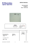
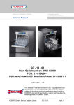
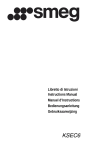
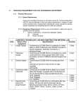
SERVICE MANUAL DISHWASHER COMPACT Dishwasher COMPACT © AEG Hausgeräte GmbH Muggenhofer Straße 135 D-90429 Nürnberg Germany Publ.-Nr.: 599 516 219 EN 911 328 ..... Fax +49 (0)911 323 1022 Spares Operation Edition: 01.03 Spares Operation - R.Kurzke 02/03 -1- 599 516 219 EN Index 1. Technical specifications ......................................................................................... 3 2. 3. Installation water drainage ..................................................................................... 3 Components .......................................................................................................... 4 Capacitor ............................................................................................................... 4 Pressure switch ..................................................................................................... 4 Heater element ...................................................................................................... 4 Circulation pump .................................................................................................... 5 Drain pump ............................................................................................................ 5 NTC temperature sensor ....................................................................................... 5 Programmer ........................................................................................................... 5 Detergent dispenser .............................................................................................. 6 Rinse aid dispenser ............................................................................................... 6 Inlet valve ............................................................................................................... 6 Anti flood switch ..................................................................................................... 6 Water softening system ......................................................................................... 7 4. 5. Position of components ................................................................................. 8 - 11 Water course scheme .......................................................................................... 12 6. 7. Water inlet ...........................................................................................................13 Rinsing system .................................................................................................... 14 8. 9. Strainer system .................................................................................................... 15 Level control system ............................................................................................ 16 10. Inlet system / Overfilling/leakage protection (old version) ...................................17 Drain system ........................................................................................................ 18 11. 12. Regeneration ....................................................................................................... 19 Thermostats ......................................................................................................... 20 13. 14. Temperatur and safety systems .......................................................................... 21 Wirings and diagrams .................................................................................. 22 - 25 15. Service informations ............................................................................................ 26 Spülraum ............................................................................................................. 26 Housing ................................................................................................................ 27 Panel / base plate ................................................................................................ 28 Components (lower region) ................................................................................. 29 Door components ................................................................................................ 30 Door switch .......................................................................................................... 31 Rinse aid dispenser / detergent dispenser coil .................................................... 32 Pressure switch / Anti-siphon valve / level control container ............................... 33 Thermostats / Heater element ............................................................................. 34 Programmer / switch unit / float switch / inlet valve ............................................. 35 Circulation pump / drain pump ............................................................................. 36 Softener / regeneration valve............................................................................... 37 Leakage points ............................................................................................ 38 - 39 16. Fault tracing ................................................................................................. 40 - 42 Spares Operation - R.Kurzke 02/03 -2- 599 516 219 EN 1. 2. 3. 1. On/Off-button Temperature selector Extra drying effect 4. 5. 6. Technical specifications Power supply: Heater element: Power rating: Fuse required: 230 V - 50 Hz 1200 W 1280 W 13 A Height: Width: Depth: 460 mm 450 mm 480 mm Water pressures: min. 50 KPa (0,5 bar) max. 1000 kPa (10 bar) Capacity: 5 settings 2. Programme selector Indicator lamp Salt indicator lamp Installation water drainage Place the discharge hose over the sink as illustrated. It may not at any point be higher then 75 cm over the surface which the dishwasher is standing on. If runs higher, operation of the dishwasher might be impaired. It is also important to ensure that the inside diameter of the hose is not less than 13 mm at any point. If the discharge hose is too long it can easily be cut to the right length. Cut the hose to a suitable length, using a sharp knife. Fit the elbow supplied onto the end of the hose. Spares Operation - R.Kurzke 02/03 -3- 599 516 219 EN 3. Components Capacitor The circulation pump is connected to a capacitor. 2,0 µF for UK 2,5 µF for Europe Pressure Switch The pressure switch controls the water level. Without water, contact is closed. Adjusting: Turning the marked screw clockwise Turning the marked screw anti clockwise + level - level Heating element Power output Resistance approx 1200 W 42 W Spares Operation - R.Kurzke 02/03 -4- 599 516 219 EN Circulation Pump The circulation pump is driven by an asynchronous motor with an starting winding. The starting winding ist in circuit with a 2,5 µF (Euro) capacitor. (2 µF UK) Rating: Main winding resistance Starting winding resistance 60/80 W 158 Ohm 158 Ohm Drain Pump The drain pump is driven by a synchronous motor. Power output Pump rate Main winding resistance 21/19 W. 10-12 l/min. 200 Ohm Thermostats (normally open) 45°C closes at 41°C opens at 33°C 55°C closes at 50°C opens at 42°C 65°C closes at 61°C opens at 53°C Overheating protection (normally closed) opens at 83°C closes at 0°C Programmer ELBI Spares Operation - R.Kurzke 02/03 -5- 599 516 219 EN Detergent dispenser Coil resistance 3000 Ohm Rinse aid dispenser Rinse agency capacity Solenoid coil resistance 140 ccm 1900 Ohm Inlet valve Capacity, max, Resistance 4 l/min 4800 Ohm Anti flood switch If the anti flood swich in the base tray is activated, all components are switched off except the drain pump Spares Operation - R.Kurzke 02/03 -6- 599 516 219 EN Water softening system Operation of the water softening system When water is admitted, the inlet valve (1) opens and the hard water flows down into the ion exchanger (5), through which it flows and is softened before flowing through the water inlet (6) and then being sprayed into the Washing chamber. !n the meantime, the container for the regeneration water (2) is also filled with water. lf the rubber plug (3) at the rear of the machine is in place as shown in the ilustration, the machine can handle water with a hardness of up to 20'dH. !f the rubber plug is removed. The regeneration water volume will be increased, and the machine can then handle water with a hardness of up to 35°dH. During the dishwashing programme, the ion exchanger will gradually be filled with lime and, to be able to soften the water during the next dishwashing cycle, the ion exchanger must be restored to its original condition. This is done by a process known as regeneration, which takes place according to the actual programmer diagram. The solenoid valve (7) between the salt container and the ion exchanger will then open, and regeneration water will flow into the salt container (4). A corresponding amount of water saturated with salt is thus forced into the ion exchanger. The salt solution is present in the ion exchanger during the last rinse, and the small plastic balls will be recharged with sodium ions. According to the actual programmer diagram, the inlet valve will open and will allow about 2 litres of water to flow through the ion exchanger to flush away the now dissolved lime residues. The lime-rich water is then flushed immediately out to drain, and the machine is reset and ready for the next water fill. The whole of this process is integrated into the programme of a machine with water softening, and thus takes place fully automatically. It should also be noted that it is important to use only coarse salt, since fine-grained salt would. form lumps. Water which is rich in lime is said to be "hard". Water hardness is measured in German degrees of hardness (dH). Water up to 10dH is normally regarded as soft, and above this value, it is regarded as hard. The phosphates in the detergent can handle the hardness in soft water. But if the water is hard, precipitations will occur, i.e. lime will be deposited on the dishes and in the dishwasher. Spares Operation - R.Kurzke 02/03 -7- 599 516 219 EN 4. Position of components Door opener Inner door Outer door Door seal Programmer / Timer Signal lamps Switches (temperature) Spares Operation - R.Kurzke 02/03 -8- 599 516 219 EN Housing Coil for detergent dispenser Rinse-aid dispenser Door switch Basek rails Coarse sieve Interference filter Fine strainer Heating element Thermostats Base plate Spares Operation - R.Kurzke 02/03 -9- 599 516 219 EN Softener Inlet hose Drain hose anti-siphon valve Regeneration valve Reed switch salt indicator Inlet valve Float switch Pressure switch Drain pump Water collector Base plate Air chamber Spares Operation - R.Kurzke 02/03 - 10 - Circulation pump 599 516 219 EN Spray arm Sealing ring Pump housing Cup support Cuttlery basket Dish rack Basket roller Spares Operation - R.Kurzke 02/03 - 11 - 599 516 219 EN 5. Water Course Scheme Spares Operation - R.Kurzke 02/03 - 12 - 599 516 219 EN 6. Water Inlet The water flows into the regeneration dosage chamber via inlet valve, over air break, into regeneration dosage chambers and into softener The level control container operates the pressure switch. Spares Operation - R.Kurzke 02/03 - 13 - 599 516 219 EN 7. Rinsing system The function of the rinsing system is to wet the dishes loaded into the machine. The electric motor of the circulation pump is delivered with the impeller fitted to it. Half the pump casing forms part of the plastic chassis, and the other half is bolted in position inside the washing chamber. This arrangement ensures, that the joint between the two halves of the pump casing is inside the washing chamber. An O-ring provides the seal between the motor assembly and the chassis. The rating of the electric motor is 60 watts(50 Hz) or 80 watts(60 Hz) and the pump circulates around 30 litres per minute. The electric motor needs assistance at the instant of starting, which is provided by a starting capacitor. The motor mounting is very important to the sound level. Since the movements of the motor are a minimum at the centre, the motor is secured to a rubber mounting in the centre, at the rear end of the motor. To ensure that no vibrations will be transmitted from the motor to the base plate, a plastic foam spacer strip is fitted to the bottom of the chassis. The pump casing half which is inside the washing chamber also contains the spray tube bearing with a stainless steel shaft. The underside of the spray tube is fitted with a seal ring to minimize leakage. The shape and orientation of the holes in the spray tube are such that the dishes furthest away in the corners of the machine will also be effectively washed. The spray tube rotates anti-clockwise at a speed of 10 - 20 1/min. If the speed is too high, the dishwashing results will be poor, and if the speed is too low, the spray tube may stop al-together. The pressure in the spray tube is just over 0.2 kg/ cm². The spray tube is retained by a ceramic nut with a left-hand thread, to en-sure that the rotation of the spray tube will not cause the nut to unscrew itself. This means that the nut must be un-screwed in the wrong direction. Spares Operation - R.Kurzke 02/03 - 14 - CERAMIC NUT SPRAY TUBE SEAL RING PUMP CASING HALF MOTOR MOUNTING O-RING PLASTIC TRAY CIRCULATION PUMP 599 516 219 EN 8. Strainer system The strainer system is one of the systems which are most important to the performance of the dishwasher. The design of this system is largely decisive to whether the dishwasher will be able to perform its most fundamental task: to wash the dishes clean. The strainer system must trap particles of food, etc. and ensure that these particles will not be recircu-lated and deposited back on the dishes. Another consumer requirement is that the strainer system must be self-cleaning, so that it will not be necessary to wash the strainers by hand every time or every other time the dish-washer is used. The strainer system consists of two parts which jointly contain three different strainers, each of which with its own particular task. Coarse strainer The fine strainer consists of a shaped stainless steel plate which is perforated with 0.5 mm diameter holes and is retained in a plastic frame. The dishwashing water passes through this strainer about 420 times during a normal dishwashing programme. The bottom of the chassis is designed in such a manner that particles will continually be flushed away to the coarse strainer. All particles larger than 0.5 mm will be trapped, and the water flowing through the strainer will thus be virtually clean. The performance of the strainer is highly dependent on the suction of the circulation pump Fine strainer being equally distributed over the entire strainer area. If the suction is higher at any one point, particles will be drawn through the fine strainer at that point, and they would then disintegrate and would be very dif-ficult to trap. It is also very important for the plastic frame of the fine strainer to seal well against the chassis, so that particles will not by-pass the strainer and be deposited back on the dishes. The fine strainer also includes a small plastic boss. This is designed to prevent the build-up of pressure and air cushions under the strainer. An air cushion under the fine strainer would otherwise prevent the water from flowing through the fine strainer, and insufficient water would then be supplied to the circulation pump. Particles are thus flushed continuously down into the coarse strainer, where they are retained until the water is pumped out to drain. The coarse strainer is also designed to trap larger particles, such as pieces of meat, toothpicks, etc. To retain the good dishwashing properties of the machine, the consumer must empty and rinse the strainers as soon as they show signs of clogging. Spares Operation - R.Kurzke 02/03 - 15 - 599 516 219 EN 9. Level control system There are two basic ways of metering the right amount of water into a dish-washer. The first is to open the inlet valve for a certain predetermined period of time, while the other is to use some means for measuring the water level in the machine. The major disadvantage of the first method is that if the mains water pressure is low (which is very common in Europe), the time allowed will be too short to fill the machine with a sufficient amount of water. A time-controlled machine needs a water pressure of at least 1.0 - 1.5 kg/cm2. The Compact dishwasher is level-controlled and will perform satisfactorily at mains water pressures down to 0,5 kg/ cm². Operation of the level control system of the Compact dishwasher As the machine is being filled with water, the water level in a level control container located on the side, outside the chassis will also rise. The container is connected to a pressure switch by means of a hose. As the water level in the contairier rises, the air pressure in the hose will also increase and will act on the pressure switch. When the pressure has risen to a preset value, the pressure switch will open, which will cause the inlet valve to close. The programmer motor can now advance to the next step. When the drain valve then empties the machine, it will also empty the level control container, and the pressure switch will revert to its original position, in preparation for the next water fill. The inlet hole of the level control container is below the strainer, and the water in the level control system is therefore always clean and filtered. If the water level should drop for any reason while dishwashing is in progress, the pressure switch will close, which will interrupt the water circulation, and the water heating possibly restart the programmer and allow the programmer to advance in the programme. It is important for the machine to be perfectly level when it is in operation, since a 5 mm difference in level corresponds to about 1 litre of water. between 20 - 24 mm PRESSURE SWITCH LEVEL CONTROL CONTAINER Air pressure, p Water level Water pressure, p Washing chamber Level control container Spares Operation - R.Kurzke 02/03 - 16 - 599 516 219 EN Old version Inlet system - old version A The inlet hose is a rubber hose with plastic cover. The coupling nuts are made of plastic (which reduces the risk of crossedhreads) . The inlet hose is inside the washing chamber when the machine is delivered, and the consumer must fit the hose when installing the machine. He must then also decide whether the hose is to run to the right or to the left. B On the machine, the inlet hose is connected to the inlet valve (also known as solenoid valve). When the inlet valve is energized (via the programmer) the valve will open and water will flow into the machine. When the level controller has sensed that the water has reached the correct level, it will open the power supply circuit to the inlet valvet and the valve will close. The valve is designed to open and close slowly. It is important to ensure that no harmful pressure surges will be caused in the water supply mains. D Flooding. If a component or seal should start to leak, the water will collect on the base plate and will activate the floating body. To some extent, the wall along which the water flows serves as a brake,so that spillage of a few drops will not cause the moisture sensor to trip. C Overfilling protection. If the level sensor should fail to operate and the inlet valve should remain open after the water has reached the correct level, the water will run across an overflow baffle down into the base plate, where the floating body of the flooding protection system will close the inlet valve and will prevent water damage. Overfilling/leakage protection - old version E The inlet valve also incorporates a mechanical tripping actuator. The tripping actuator is operated by a floating body . If water should leak into the base plate for reason, the floating body will close the inlet valve mechanically. The leakage protection will operate even if the power supply cable is disconnected. Reverse flow protection. F This prevents contaminated water from the dishwasher from being drawn back into the water mains, even if a vacuum should occur in the water mains. Spares Operation - R.Kurzke 02/03 - 17 - 599 516 219 EN 10. Drain system The system consists of inner and outer drain hoses and a drain pump, and its function is to transport the contaminated water as efficiently as pos-sible from the machine to the waste water system of the buildin The drain pump is connected to the chassis at the coarse strainer and is sealed with an O-ring. The motor is a perOUTER DRAIN HOSE manent-magnet motor, with the rotor.mounted inside a plastic housing and the stator fitted to the outside of the plastic housing. The design is such that the pump has no traditional shaft seat which always invol-ves the risk of leakage. DRAIN CASING INNER DRAIN HOSE DRAIN PUMP The pump performs equally well in both directions of rotation, and the direction in which it rotates is a matter of pure chance. This also means that the pump is vir-tually proof against jamming. If some object should enter the pump casing and jam the impellar, the motor will immediately make a new starting attempt in the op-posite direction. Even if the impellar is seriously jammed (e.g. by a toothpick), the motor will most probably release the impellar within about a second. The power consumption of the motor is 23 watt, and the pump capacity is about 10 I/min. The internal drain hose is connected to the drain pump. To prevent the risk of the machine being emptied by siphon action, the hose routes the drain water through a loop running up to the top of the chassis and then through the outlet at the bot-tom of the machine, to the outer (visible) drain hose. A hole is provided at the highest point of the inner drain hose for venting the system. If the drain hose is permanently connected to a water trap, it is very important that the inside diameter of the drain system should not be less than 13 mm at any point. New antisiphonic device If the end of the take-off hose is below the level of the water in the wash space, a siphon effect is possible, that is, the machine runs empty. This is avoided by the ventilation through the anti-siphon valve. Spares Operation - R.Kurzke 02/03 - 18 - 599 516 219 EN 11. Regeneration The water chamber for regeneration contains 350 ml water. During regeneration, the regeneration valve is energized. The 350 ml water runs into the salt container and mixes with the salt to form a brine solution. In the top of the salt container there is an opening with a small filter, from here the brine solution enters the softener where the resins are regenerated. The softener has 5 settings and can be adjusted to suit the degree of water hardness. Spares Operation - R.Kurzke 02/03 - 19 - 599 516 219 EN 12. Thermostats The thermostats are pressed into the tubular mountings in the plastic chassis. They measure the temperature on the outside of the plastic wall, which leads to a certain difference between the water temperature and the thermostat temperature. However, the specifications of the thermostats take this into account. (In one particular case, the same thermostat is used for two different temperatures. This is possible because the thickness of the chassis is different at the two thermostat mountings. The thicker the wall, the greater the temperature difference and the higher the water temperature.) Depending on the Programme selected, the thermostats will be switched in, and will interrupt the power supply to the heater element via the programmer when the water has been heated to the required temperature. As in the case of al! other components, there is a certain amount of tolerance on the nominal temperature of the thermostats. For the breaking temperatures, the tolerance is ±3°. There is also a "differential", i.e. a difference between the temperature at which the thermostat opens the circuit and the temperature at which it returns to the original position. This differential is 8°C. The breaking values are adjusted to give the following water temperatures: 45, 55, 65 and 72'C. Colours coding of the thermostats A = brown B = black C = grey D = white Spares Operation - R.Kurzke 02/03 83°C 65°C 55°C 40°C (anti boiling protection) (two) - 20 - 599 516 219 EN 13. Temperature control and safety Systems The dishwashing detergents available on the market today require a certain water temperature before they can dissolve the food residues in a satisfactory way. A temperature control system consisting of a heater element and thermostats ensures that the water will be heated to the correct temperature. Heater elements is 1200 watt. In addition, the machine includes a safety system, the function of which is to protect the temperature control System against accidental overheating. The overheating safety system is very important. Several components and systems are involved in different ways. The following conditions must be satisfied before the element can be switched in: The rnain switch must be closed, the door must be closed so that the door switch is closed, and a Programme must have started. The machine must contain the correct amount of water (as determined by the level control pressure switch). The safety system will trip if The quantity of water is insufficient. The water temperature has risen to about 85°C without the thermostat tripping. In addition, two overheating protections are incorporated into the element, i.e. one at each connection end. These are designed so that they will burn off if the element is switched on but has no cooling water around it. Spares Operation - R.Kurzke 02/03 - 21 - 599 516 219 EN 14. Wirings (Example DSC 14) Spares Operation - R.Kurzke 02/03 - 22 - 599 516 219 EN Diagram (Example DSC 14) Spares Operation - R.Kurzke 02/03 - 23 - 599 516 219 EN Wirings (Example DSC 382) Spares Operation - R.Kurzke 02/03 - 24 - 599 516 219 EN Diagram (Example DSC 382) Spares Operation - R.Kurzke 02/03 - 25 - 599 516 219 EN 15. Service Informations Coarse filter The purpose of the coarse filter is to catch large objects. Make sure that the filter is always clean. Fine filter It is just important to keep this filter clean. The fine filter can easily be lifted out for cleaning when the coarse filter is removed at first. Spray arm The spray arm is to be removed by unscrewing the nut clockwise (it has a left-handed thread) and lift of the spray arm. Spares Operation - R.Kurzke 02/03 Sealing ring To clip out he sealing ring a screwdriver gives support. - 26 - 599 516 219 EN You need screwdriver Torx TX20 Housing After removing the housing screws (lay the machine on its side) from the bottom of the machine, the housing is unclipped front and back from the catches and can be removed. All components from the left and right side are now accessible. Coil for detergent dispenser Softener anti-siphon valve Rinse-aid dispenser Pressure switch Air chamber Programmer / Timer Drain pump Spares Operation - R.Kurzke 02/03 Interference filter - 27 - Thermostats 599 516 219 EN Replacement of the panel Remove the screws from the panel frame. Remove the turning knob. Carefully unclip the front . Before finally opening, unclip the lamps. Remove the base plate The base plate of the machine is held with screws on the lower panel and at the bottom. Lay the machine on its back and lift off the base plate. It contains the bosses for the overflow water and the flooding switch. After removal you come to the most important functional components. Spares Operation - R.Kurzke 02/03 - 28 - 599 516 219 EN Switches (temperature) Programmer / Timer Thermostats Drain pump Air chamber Interference filter Circulation pump Float switch Regeneration valve Softener Inlet valve Heating element Spares Operation - R.Kurzke 02/03 - 29 - 599 516 219 EN Outer and inner door They snap together and are held by plastic latches, on the under side. They can easily be unsnapped Replacement of the components within the door. After removing these screws, the door handle and detergend dispenser flap can be removed from the inner door. After removing the spring, the door-opener can be removed from its hinges. The seal is easily be clipped in the inner door frame. Re-assembly is carried out in the reverse order. Spares Operation - R.Kurzke 02/03 - 30 - 599 516 219 EN To remove the inner door Remove the lower panel and the outer door. Open the door and remove the four screws (two on each side) securing the rack rails. Open the door to an angle of about 130° and carefuly relese the hinge pin on the right hand side. On the left hand side, the hinge pin is inserted in a hole without slot. Door switch Remove the the screws on the under side of the upper panel. Lift off the upper panel. The door switch is easily be screwed. Spares Operation - R.Kurzke 02/03 - 31 - 599 516 219 EN Remove this screw to dismount the rinse aid dispenser unit The coil with tappet as support for the detergent dispenser is held by two screws. Spares Operation - R.Kurzke 02/03 - 32 - 599 516 219 EN The pressure monitor is simply screwed. The motor capacitor is screwed by a nut. Anti-siphon valve The air should be able to enter the hose from the holder - not the other way around! The take-off hose ventilation can be unscrewed for cleaning when necessary, in case these rubber parts in the interior of this valve become dirty or stuck because of residues. Spares Operation - R.Kurzke 02/03 - 33 - Level control container (Air chamber) Remove the srew to lift off the level control container for cleaning. 599 516 219 EN Thermostats The mounting for the thermostats is screwed at the right side of the air chamber. After its release, the thermostats can be removed. Heater element After the removal of the nut and the heater clip in the sump under the fine strainer, the heater element can be drawn forward through the chassis opening to remove.. Spares Operation - R.Kurzke 02/03 - 34 - 599 516 219 EN Programmer The programmer is secured to the front of the chassis by means of two screws. Remove the programmer from the right side of the chassis. Switch unit The switch unit is secured by means of screws and easily to remove. Float switch The float switch is snapped out with a small screwdriver and can be taken out of its mounting. After removing the protective cap, the microswitch can be snapped out. Inlet valve The inlet valve is mounted in the same place as the float switch. After the removal of the hose, the valve can be drawn out of the chassis with suitable pliers. Circulation pump After loosening the screws of the holder, the circulation pump can be taken out of the pump chamber. Drain pump To dismount the drain pump, the hose clamps are released and the screws removed. Here you can see how the hose clamps can be re-tensioned with wire cutting pliers. Spares Operation - R.Kurzke 02/03 After removing the drain pump the tubing-bow with seals, fitted in the pump chamber, is accessible. - 36 - 599 516 219 EN Softener 1 To dismount the water softener, these attachment screws are removed. 1 4 2 The connections on the reed switch are removed. 3 The hose connections are detached. 4 The large nut of the salt hol der must be released . 5 2 5 A spanner is useful in removing the recycling inlet nut. 6 Now the complete unit can be removed. 6 3 Regeneration valve After undoing the screws of the recycling valve, this can be removed. Spares Operation - R.Kurzke 02/03 - 37 - 599 516 219 EN Leakages. Service solutions: Take of the cover to be able to see the Container on the left hand side. Let the dishwasher take in water and check the level. If the level is too high (leakage through the top of the Container) - adjust the pressure level switch - check assembling ofthe Container to tub, misaligned oring or screw not tightened. - Check the Container it self (leakages between the welded base between 20 - 24 mm and the Container walls) Water level Low water level. Check ifthe Container is clogged. Clean it with hot water (after disassembly it from the pressure level switch hose and the tub) under a tap. If the water level is to low, adjust the pressure level switch. The drain pump is always running if the water prot device is activated. If there is a leaking point and the water prot device is activated the d-pump is running continuously. There are no possibilities for the drain system to evacuate water from the bottom tray, so when the d-pump has emptied the tub it will still drain but without draining any water out: Customer complaint, not draining?! Even in this case the Service tech have to locate the leaking point Leakages: If the leakage point is located to the d-pump check: - the two screws holding the d-pump on to the tub. - the oring between the d-pump / tub (misaligned, distorted) ?? - the housing three screws on the d-pump. If the leakage point is located to the d-pump check: - the two screws holding the bracket / circulation pump in place. - disassemble the circulation pump from the tup and check for plastic burr in the tub / oring connection. Spares Operation - R.Kurzke 02/03 - 38 - 599 516 219 EN Check the locknut under the salt cap to ensure it is fully tightened. It should not be possible to unsrew by hand. In the case of leakage, here more checkpoints Spares Operation - R.Kurzke 02/03 - 39 - 599 516 219 EN 16. Spares Operation - R.Kurzke 02/03 - 40 - 599 516 219 EN Spares Operation - R.Kurzke 02/03 - 41 - 599 516 219 EN Spares Operation - R.Kurzke 02/03 - 42 - 599 516 219 EN