1
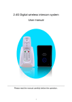
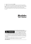
thermamed smartcare
Patient Warming System
Service Manual
Rescue System
Date: 28.01.2003
Service Manual Rescue System
Page 1
Contents:
Introduction.......................................................................................................................3
Visual check......................................................................................................................3
Calibration and software updates..................................................................................5
Checking the resistance values of carbon fibres (optional) ......................................6
Assembling the control unit ............................................................................................6
Repairs ..............................................................................................................................7
Annex.................................................................................................................................8
Date: 28.01.2003
Service Manual Rescue System
Page 2
Introduction
Maintenance must be carried out in accordance with EN 60601-1 and is prescribed
every 2 years for medical appliances. Calibration work may only be done with the
calibration kit supplied by thermamed smartcare GmbH. Use only original
replacement parts. Maintenance may only be carried out by trained and authorised
persons.
Attention: The prescribed test of electrical safety according to EN 750 / EN 751
has to be carried out irrespective of this Service Manual. Therefore observe
your country’s laws.
Visual check
Segments
Check all segments, including all cables and connectors, for mechanical damage.
In particular:
•
Check the segments for holes and tears.
•
Check the cables for breaks in the sheaths and cable strain relief devices.
•
Check the connectors for corrosion and mechanical stability.
If a segment has at least one of the defects described above, send it to thermamed
smartcare GmbH for repairs.
Control units:
Check the housing of the control unit for mechanical damage (cracks and holes) and
check the mechanical function of the pushbuttons.
Replace faulty housings, front overlay, display discs and holders; see section
Repairs
If one of the pushbuttons is mechanically defective, send the control unit to
thermamed smartcare GmbH for repairs.
Switch the appliance on and check that the control unit starts correctly.
Sequence after the ON switch of the control unit is pressed:
•
Brief acoustic signal
•
All LEDs flash up for 2 sec
•
The green LEDs of the temperature display run through
•
Double click of the safety-relay can be heard
•
LED Column (4) shows battery voltage / vehicle network voltage
•
LED Column (3) shows the actual blanket temperature
Date: 28.01.2003
Service Manual Rescue System
Page 3
The sequence is finished when the LED at the 37°C button is shinning. The blanket
temperature is preset to 37°C.
If the control unit does not carry out the start procedure correctly, send it to
thermamed smartcare GmbH with a description of the fault for further checks.
The calibration kit contains:
- Software package
- Connection cable [PC –control unit]
- Adapter for Calibration box [temperature defaults]
- Tweezers for replacing the ICs
8
6
7
9
42°C
42°C
37°C
!
37°C
32°C
smartcare
3 5
2
1.) On/Off switch:
(I = On, 0 = Off)
2.) Temperature setting:
(37°C + 42°C)
3.) Actual temperature display
/ Fault code display
(32°C to 42°C)
4
1
4.) Battery status display
5.) Fault display (LED)
6.) Socket for rescue blanket (yellow)
7.) Socket for supply voltage (blue)
8.) Connector for the rescue blanket (yellow)
9.) Connector the supply voltage (blue)
Date: 28.01.2003
Service Manual Rescue System
Page 4
Calibration and software updates
Note: see the chapter in the annex for the installation of the HDS_MESS calibration
software!
Unscrew and remove the four screws on the rear to open the control unit. You can
now remove the rear.
Fuse
Pin
X5_1
Haupt
Steckerleiste
PIC
Controller
Place the plug for connecting the PC to the CPU on terminal X5_1 so that the cable
marked black is placed on the second pin from the bottom (see sketch).
Note: Wrong placed connection cables can cause the destruction of the
controller.
You can now start the HDS_MESS software. Furthermore the controller must be
connected with the supply voltage.
Note: Do not switch on the controller!
The control unit may report one or more faults after being switched on. Cancel these
faults by clicking the button RESET ERROR.
Use the command READ EPROM to display the EPROM's basic settings on the PC.
The control unit is then recalibrated. Carry out the following steps in the order shown:
•
Set the rotary switch on the calibrating box to 30°C and connect to the control
unit's yellow output socket. Always use the delivered Adapter Cable.
•
Set the GAIN fields to zero.
•
Adjust OFFSET so that both channels show 30°C.
•
Set the rotary switch on the calibrating box to 45°C and adjust GAIN so that
the PC displays the temperature 45°C.
•
Check the other temperatures by means of appropriate settings at the
calibration box.
Date: 28.01.2003
Service Manual Rescue System
Page 5
If a temperature does not fit, set the box to 45°C again and alter the GAIN setting by
one step. Now repeat the temperature check.
Once you have calibrated all channels, end the procedure by clicking the SAVE
EPROM button. Then click the SOFT RESET button and the control unit starts
again.
Checking the resistance values of carbon fibres (optional)
The HDS_MESS software is used here as well. Remove the control unit from the
housing and connect it to the PC as described above.
Instead of the calibration box, connect a warming segment to the control unit's yellow
output. Switch on the controller and take care that it is in normal mode. You can now
read off the output voltage and the output current on the PC; calculate the resistance
using Ohm's law:
U/I = R
Assembling the control unit
Remove the Adapter Cable. Use the four fastening screws to fix the rear. (Do not
forget the seal!)
Date: 28.01.2003
Service Manual Rescue System
Page 6
Repairs
Only the repairs described here may be carried out. All other repairs to the control
unit and the warming segments must be carried out by thermamed smartcare
GmbH.
Changing the appliance's fuse
Remove the rear cover and change the fuse. Only use fuses with the same values as
the original.
Replacing the appliance's seals
Remove the rear cover and exchange the seal
List of Replacement parts:
On request
Date: 28.01.2003
Service Manual Rescue System
Page 7
Annex
Installing the program HDS_Mess
Insert the CD, start Set-up and follow the prompts on the screen.
Configuration of the program HDS_Mess
After the installation, the program must be configured for the PC: to do this, start the program
and double-click on the button CONFIG RS 232 to open the configuration routine; make the
following settings:
Button
Setting
Default setting
COM port
Select the COM port for the
interface
Baud pate
Select transmission speed
9600
Parity
Parity bit setting
none
Data bits
No. of data bits
8
Stop bits
No. of stop bits
1
Input Quere Size
512
Output Quere Size
512
Set CTS mode
Off
Set XON/XOFF
Off
Timeout
Waiting time
5
Fault messages
!
Important: this list can only be used as a starting point. Because many of
the faults listed here affect each other there is no guarantee that the cause
of the fault can be determined exactly.
Date: 28.01.2003
Service Manual Rescue System
Page 8
Display
Problem
Possible fault
Remedy
Control unit cannot be
switched on
Vehicle network connector not
plugged in
Fuse triggered
Plug vehicle network connector in
Blanket/bag does not warm up
Blanket/bag wrong way round
Blanket/bag too warm
Setpoint temperature set too high
Objects on the blanket/bag causing
heat build-up
Blanket/bag still switched on
When
the
blanket/bag
is
disconnected
from the control
unit
a
fault
message
is
displayed and the
safety cut-off is
activated.
LED 2
Fault no. 2
Blanket/bag defective
LED 1
and 2
LED 2
and 3
Fault no. 3
Blanket/bag defective
Fault no. 6
Input voltage too high
LED 1,
2
and 3
Fault no. 7
Input voltage too low
LED 4
Fault no. 11
Connected blanket/bag is too cold
Defective thermo sensor
Fault no. 12
Excess temperature
LED 1,
3
and 4
Fault no. 13
Excess temperature
LED 2,
3
and 4
Fault no. 14
Excess temperature
LED 1,
2, 3
and 4
Fault no. 15
Control unit defective
Control unit no longer working
and shows a fault message
Safety cut-off activated by a fault
and 1
and 2
LED 3
and 4
Date: 28.01.2003
Replace fuse.
(If this occurs again, have a technician
check the unit). The fuses are in the
control unit and, with standard vehicle
network connectors, in the connector as
well.
Turn the blanket/bag the right way
round.
Reduce setpoint temperature
Remove the objects from the
blanket/bag.
Switch the blanket/bag off before pulling
the connector out.
Replace the blanket/bag, inform service
quoting the fault code.
Replace the blanket/bag, inform service
quoting the fault code.
Use only power supply units that
correspond to the stated operating
voltage.
Use only power supply units that
correspond to the stated operating
voltage. If using with a battery, the
battery is probably completely
discharged; replace with a charged
battery.
See information at the end of the table.
Replace the blanket/bag, inform service
quoting the fault code.
Let the blanket/bag cool down, smooth
the blanket out; if this problem occurs
again, shut the complete system down
and inform service quoting the fault
code.
Let the blanket/bag cool down, smooth
the blanket out; if this problem occurs
again, shut the complete system down
and inform service quoting the fault
code.
Let the blanket/bag cool down, smooth
the blanket out; if this problem occurs
again, shut the complete system down
and inform service quoting the fault
code.
Replace the control unit, inform service
quoting the fault code.
The control unit cannot be restarted until
after you have switched it off.
Service Manual Rescue System
Page 9
Reservation of the RS 232 interface:
GND
5
1
Date: 28.01.2003
Service Manual Rescue System
Page 10