1
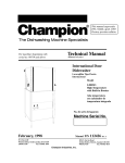
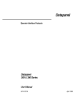
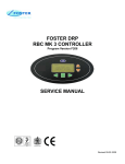
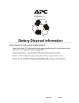
Dough Retarder Prover
Service Manual
Dough Retarder Prover
Revision 3
Dough Retarder Prover - Service Manual – RBC MKII Controller
Revision 6
June 2000
Page
2
Dough Retarder Prover
CONTENTS
Page(s)
1.
INTRODUCTION
3
2.
RBC MK 2 CONTROLLER OPERATION
5-9
Process Cycle Overview
Operating Program Parameters
Machine / Service Parameters
Operating Program Selection
User Operation
5
6
7
10
10
RBC MK 2 CONTROLLER SERVICE INFORMATION
11 - 15
Electrical Terminations
Output Regulation
System Reset
Fault Indication
Data Logger
Remote Access
Parameter Access
Engineers Test
Controller Software
Controller Software Revisions
11
11
13
13
14
14
15
15
15
16
MACHINE FAULT DIAGNOSIS
17 -19
Temperature
Humidity
Water
Product
17
17
18
19
3.
4.
GLOSSARY
Dough Retarder Prover - Service Manual – RBC MKII Controller
20
Revision 6
Page
3
Dough Retarder Prover
1.
INTRODUCTION
The cabinet is designed to retard, recover and prove dough products. When
utilised correctly the unit will enable a more consistent product quality to be
achieved.
It is therefore important that prior to working on this equipment that this manual
is read and understood.
During this manual various terminology is used. Correct interpretation can be found in the Glossary
on page 30.
If any point of operation is unclear the engineer should contact Foster Refrigerator (UK) Ltd on
(01553) 691122.
The controller contains both 'User Parameters' and also 'Machine Operating Parameters'. Neither of
these parameter sets are assessable to the store operators and as such should not be disclosed to any
member of store personnel (including management).
Similarly the parameters are pre-set on commissioning to ensure consistent product quality and as
such should not be adjusted under any circumstance without prior consent in writing from Head
Office bakery personnel.
Dough Retarder Prover - Service Manual – RBC MKII Controller
Revision 6
Page
4
Dough Retarder Prover
2.
CONTROLLER OPERATION
2.1
PROCESS CYCLE OVERVIEW
2.1.1
The full automatic cycle consists of 4 stages. These are fast chill, storage, recovery and
prove. The amount of time available between the bake time and current time will depend
how much of each cycle is carried out.
For the purpose of this general overview it has been assumed that the controller has
sufficient time with which to carry out a complete cycle.
Throughout paragraph 2.1.2 reference should be made to the process graph below.
Prove Extension / H old
Prove Set Point
H old
Duration
R ecovery Set Point
Fast C hill Duration
Prove H old
Tem perature
Storage
Set Point
Recovery D uration
Prove D uration
Fast C hill Set Point
2.1.2
Upon initiation of a complete cycle the controller will chill the chamber to a pre-set
temperature (fast chill). When this temperature has been reached the machine will hold
the chamber at a temperature (storage) for a time calculated by the controller. The
controller calculates how long this temperature is maintained using the bake time and the
remaining process times.
An illustration of this is;
Assuming that the current time is 09:00 and the bake time is 18:00 the total time for
the cycle is 9 hours.
A program is selected where the recovery time added to prove time is 6 hours.
The controller would hold the chamber at the storage temperature for 3 hours.
When the time calculated for the next stage is reached the controller will change from the
storage mode to the recovery mode. During the recovery mode the controller increases
the temperature of the chamber linearly from the storage temperature to the recovery
temperature over ¾ of the given period of time. If other parameters allow it steam may
be introduced during the later parts of this stage.
Dough Retarder Prover - Service Manual – RBC MKII Controller
Revision 6
Page
5
Dough Retarder Prover
Upon completion of the recovery cycle the prove cycle commences. The chamber is then
increased to a higher temperature over ¾ of given set time period. During this stage
steam is introduced into the chamber as required to maintain the required humidity.
When the prove part of the cycle is complete the operator is advised both audibly and
visually that the current program is complete and is given an option to either extend the
prove time or hold the product. Assuming that these options are not selected the cycle is
complete and as such is halted.
If the product is not ready at the bake time then a prove extension can be selected.
Similarly, if the product is ready but there is no oven capacity the product can be held.
The duration of both prove extension and prove hold are governed by a number of
machine parameters (see paragraph 2.4).
2.2.
PARAMETERS
2.2.1
Within the controller there are 10 process operating programs numbered 0 to 9. These
programs are selected automatically by the controller based on bake time and current
time. More information on program selection is found in paragraph 3.5.
2.2.2
Programs 1 to 9 contain full automatic cycle parameter information with program 0 being
a prove only program.
2.3
OPERATING PROGRAM PARAMETERS
2.3.1
PROGRAMS 1 - 9
Programs 1 - 9 each contain the parameters detailed below;
Fast Chill Duration
The time period at the start of the automatic cycle which the controller refrigerates
continuously unless terminated by the 'Fast Chill Set Point'.
Fast Chill Set Point
Termination temperature during the fast chill operation if fast chill duration has not first
been exceeded.
Storage Set Point
The temperature at the end of the fast chill stage at which the controller holds the
chamber until the recovery stage begins.
Recovery Duration
The time taken for the temperature in the chamber too linearly rise from the storage
temperature to the recovery temperature.
Recovery Set Point
Temperature to which the chamber will linearly increase too following the storage stage.
Dough Retarder Prover - Service Manual – RBC MKII Controller
Revision 6
Page
6
Dough Retarder Prover
Prove Set Point
Temperature to which the chamber will linearly increase too
following the recovery stage.
Prove Humidity
The relative humidity which the chamber is maintained at during the
prove cycle subject to the 'Humidity Temperature Limit' parameter.
Prove Duration
The time taken for the chamber temperature too increase linearly
from the recovery temperature to the prove temperature.
Final Product Loaded
The time prior to the bake time after which the no further product can be loaded. The
display indicates when this time has passed.
Oven Contact
Time prior to the bake time that the oven contact operates.
2.3.2
PROGRAM 0
Program '0' is designed for proving only and as such only has the parameters listed below.
Prove Set Point
Temperature which the chamber achieves when program '0' is selected.
Prove Humidity
The relative humidity which the chamber is maintained at during the prove cycle subject
to the 'Humidity Temperature Limit' parameter.
Final Product Loaded
The time prior to the bake time after which the no further product can be loaded prior to
the bake time. This time is also used as the default end time when starting the cycle. The
display indicates when this time has passed.
2.4
MACHINE / SERVICE PARAMETERS
Defrost Termination Temperature
The temperature which the coil probe must sense prior to the termination of a defrost.
Drip Time
The time at the end of a defrost prior to the refrigeration output switching on.
Humidity Hysteresis
The value about which the humidity cycles during the prove mode.
Dough Retarder Prover - Service Manual – RBC MKII Controller
Revision 6
Page
7
Dough Retarder Prover
Humidity Temperature Limit
The temperature which the chamber must reach before the humidity
system is permitted to operate during the prove and recovery stages.
Prove Hold Temperature
The temperature which the chamber will be maintained at if the
prove hold option is selected at the end of the automatic cycle.
Prove Hold Humidity
The humidity which the chamber will be maintained at if the prove
hold option is selected at the end of the automatic cycle.
Prove Hold Duration
The duration of each prove hold cycle. This will be governed by the 'Maximum Prove
Hold' parameter such that if 'Maximum Prove Hold' is 20 minutes and 'Prove Hold
Duration is 15 minutes then one cycle of 15 minutes followed by one cycle of 5 minutes
will be offered.
Maximum Prove Hold
The maximum total time that the product can be held.
Fan Speed Refrigeration Off
The fan speed during the storage stage when the refrigeration is off, listed as a percentage
of full speed.
Fan Speed Refrigeration On
The fan speed during the storage stage when the refrigeration is on, listed as a percentage
of full speed.
Fan Speed Recovery
The fan speed during the recovery stage, listed as a percentage of full speed.
Fan Speed Prove
The fan speed during the recovery stage, listed as a percentage of full speed.
Temperature Fault Difference
The temperature difference from correct temperature which must occur for the time set in
the 'Temperature Fault Time Delay' prior to a fault being generated.
Temperature Fault Time Delay
The time which the temperature difference set in 'Temperature Fault Difference' must
occur for prior to a fault being generated.
Maximum Prove Extension
The total number of times the controller asks if a prove extension is required before
offering a prove hold.
Additional Prove Temperature
Dough Retarder Prover - Service Manual – RBC MKII Controller
Revision 6
Page
8
Dough Retarder Prover
The temperature at which the chamber is held at during a prove
extension.
Additional Prove Time
The time duration of each prove extension.
Hours Operation Refrigeration
The amount of time in hours that the refrigeration has been
operating.
Hours Operation Heating
The amount of time in hours that the heating has been operating.
Hours Operation Humidity
The amount of time in hours that the humidity has been operating.
Humidity Control
The type of humidity generation system that is in operation.
Humidity On Time
When Humidity Control is set to pulse, the duration which the water solenoid valve is
open for.
Humidity Off Time
When Humidity Control is set to pulse, the duration which the water solenoid valve is
open for.
Plateau Prove
The percentage of the prove duration at which the prove temperature will be reached.
Plateau Retard
The percentage of the retard duration at which the retard temperature will be reached.
2.5
OPERATING PROGRAM SELECTION
The controller automatically selects the program it requires by calculating the total time
between the start time and the bake time. The program selected is governed by the
'Automatic Program Selection' parameters.
In the event of a program being selected which does not have sufficient time to run
completely the controller will operate as much of the program as possible. For example if
program 3 had a total run time (Recovery Duration + Prove Duration) of 5 hours the time
available was only 4 hours then the controller would operate the final 4 hours of the
cycle.
2.6
USER OPERATION
Dough Retarder Prover - Service Manual – RBC MKII Controller
Revision 6
Page
9
Dough Retarder Prover
The operator has no requirement to know the detailed working of the machine and simply
has to follow the instructions on the following page. As previously stated no information
regarding access to, or operation of, any parameters must be given to any store personnel
(including management).
Dough Retarder Prover - Service Manual – RBC MKII Controller
Revision 6
Page
10
Dough Retarder Prover
3.
ENGINEERS CONTROLLER INFORMATION
3.1
CONTROLLER TERMINATIONS
The controller terminations are as detailed below;
Power Supply
External Alarm
Light
Humidity
Heating
Refrigeration
Oven Contact
Defrost
Evaporator Fans
Humidity Sensor
Evaporator Sensor
Air Sensor
Door Switch
1&2
Com. 4
N/O 3
N/C 5
Com. 7
N/O 6
Com. 9
N/O 8
N/C 10
Com. 12
N/O 11
N/C 13
Com. 15
N/O 14
Com. 18
N/O 17
Com. 20
N/O 19
21 & 22
31 & 32
33 & 34
35 & 36
26 & 30
3.2
CONTROLLER OUTPUT REGULATION
3.2.1
HEATING
The heating output will not be switched on in the Fast Chill or Storage.
Heating will not be switched on for 2 minutes after refrigeration has been switched off.
The heating output is switched on and off at intervals which relate how many degrees the
chamber is below the set point. As the chamber reaches the set point the required the off
interval increases and the on interval decreases.
When the chamber temperature is 5°C or more below the set point the heating is
continuously switched on
Dough Retarder Prover - Service Manual – RBC MKII Controller
Revision 6
Page
11
Dough Retarder Prover
3.2.2
REFRIGERATION
Refrigeration will not be switched on for 2 minutes after heating is
switched off.
In prove or recovery mode and the chamber temperature has
exceeded the set point the refrigeration is regulated 60 seconds on 60
seconds off.
3.2.3
HUMIDITY
Humidity can only operate in the Prove and Recovery modes.
The humidity will only operate in the Prove and Recovery modes if the chamber
temperature is greater than that set in the service parameter 'Humidity Temperature
Limit'.
Humidity will not be switched on while the refrigeration is operating.
3.2.4
EVAPORATOR FANS
The fan speed is controlled for Prove, Recovery and Storage modes using the service
parameters 'Fan Speed Cooling On', 'Fan Speed Cooling Off', 'Fan Speed Recovery' and
'Fan Speed Prove'.
During the Fast Chill mode the fan speed will be maximum.
When the chamber is being cooled at the 'start' of a cycle, the evaporator fans will not be
switched off until the evaporator coil temperature is 5°C below the air temperature.
During defrost mode the evaporator fans will be switched off. They will not 'start' until
the defrost is finished and the evaporator coil temperature falls to 5°C below the air
temperature after the drip time is complete.
At the 'start' of a cycle if the chamber is being increased in temperature the evaporator
fans start immediately.
3.2.5
DEFROST
Defrosts do not occur in Fast Chill, Prove or Recovery modes.
Defrosts occur every 6 hours from when the evaporator coil falls below +7°C.
While in the Storage mode a defrost will occur 55 minutes prior to change over to
recovery mode.
The defrost will end when the evaporator coil temperature reaches the value set in service
parameter 'Defrost Termination Temperature'.
Dough Retarder Prover - Service Manual – RBC MKII Controller
Revision 6
Page
12
Dough Retarder Prover
3.2.6
DOOR CONTACT
The door contact is closed when the door is closed and open when
the door is open.
When the contact is opened the Heating, Humidity and Refrigeration
is switched off immediately. After 30 seconds, if the contact is still
open the evaporator fans are switched off. When the door contact is
closed again all outputs operate as normal.
If the door is open for 30 minutes or more all outputs are switched
on and the fault 'Door Open Fault' is generated.
3.2.7
OVEN CONTACT
The oven contact switches on for one second at a the bake time minus the time set in the
operating program parameter 'Oven Contact'. After one second the contact switches off
again.
3.2.8
LIGHT
The light is on if the door switch is open.
If the light is switched on from the display facia the light will not operate from the door
switch.
If the light is switched on from the display facia the light will remain on for a maximum
period of 10 minutes or until the light switch is operated again.
3.2.9
EXTERNAL ALARM
The alarm contact is activated if a fault condition occurs.
The contact will be held in on position until the alarm condition is rectified, the power is
switched off or the 'Down Arrow' is pressed.
3.3
SYSTEM RESET
It is possible to carry out a total system reset. When this is carried out all service
parameters and operating programs will return to their default values.
To carry out a system reset turn on the power with all buttons pressed. The display will
then prompt Reset ? and this will be confirmed by pressing both the Up and Down
buttons.
3.4
CONTROLLER FAULT INDICATION
3.4.1
The controller is capable of fault diagnosis within its own system. That is to say if a
probe fails or a parameter is exceeded a fault will be generated.
When this happens the display will indicate to the operator that a fault is present. When
Dough Retarder Prover - Service Manual – RBC MKII Controller
Revision 6
Page
13
Dough Retarder Prover
the cycle is stopped the faults can be displayed.
3.4.2
FAULT INDICATORS
Air Sensor Fault
Caused when the controller detects a fault with the air probe. The
controller will now operate by using the evaporator probe.
Coil Sensor Fault
Caused when the controller detects a fault with the coil probe. The
controller will now not carry out defrost operations and will not control the starting of the
evaporator fans when cooling the chamber at the 'start' of a cycle.
Humidity Sensor Fault
Caused when the controller detects a fault with the humidity probe. The controller will
now not operate the humidity system.
Defrost Termination Fault
Caused when the defrost termination temperature is not reached within 45 minutes.
Door Open
Caused when the door is open for more than 30 minutes.
Temperature Fault
Caused when the actual temperature is greater or less than the calculated temperature as
specified in the service parameters 'Temperature Fault Difference' and 'Temperature
Fault Time Delay'.
Over Temperature
Caused when the safety thermostat (set point 60°C) is operated by an over temperature
condition.
3.5
DATA LOGGER
The controller records all temperature and humidity values for a 48 hour period. This
information can be retrieved and viewed using a PC software package.
3.6
REMOTE ACCESS
All parameters can be downloaded from and uploaded to the controller a PC software
package. This can be connected either directly using the serial port located on the front
of the controller or remotely via a modem.
Dough Retarder Prover - Service Manual – RBC MKII Controller
Revision 6
Page
14
Dough Retarder Prover
3.7
PARAMETER ACCESS
3.7.1
TIME & DATE
To access and set the time and date. Stop any cycle which is
currently operating by holding the 'STOP' button for 5 seconds.
Hold the 'STOP' button and press the 'Down Arrow' and follow the
prompt on the display.
There is no need to change the time for Summer and Winter time the controller will carry
this out automatically.
3.7.2
OPERATING PROGRAM / MACHINE PARAMETERS
Stop any cycle which is currently operating by holding the 'STOP' button for 5 seconds.
Switch off the power then whilst holding down the 'START' and 'Up Arrow' switch the
power on. Continue to hold the buttons until the display prompts 'Service Program'.
Press the 'Down Arrow' and follow the instructions on screen.
3.8
ENGINEERS TEST
Within the controller there is the facility to activate each output and view each input
independently without having to operate a cycle.
To access this facility;
Stop any cycle which is currently operating by holding the 'STOP' button for 5 seconds.
Switch off the power then whilst holding down the 'START', 'Up Arrow' and 'Down
Arrow' switch the power on. Continue to hold the buttons until the display prompts
'Engineers Test ?'.
Press the 'Up Arrow' and follow the instructions on screen.
Where there are several test options, for example in relay test use the 'Up Arrow and
'Down Arrow' to select each item for test.
3.9
CONTROLLER SOFTWARE
The current revision of controller software is identified from the label on the EPROM.
Subsequent revisions of the software will be notified and details of changes contained in
each revision can be found on the following page.
Dough Retarder Prover - Service Manual – RBC MKII Controller
Revision 6
Page
15
Dough Retarder Prover
3.9.1
CONTROLLER SOFTWARE REVISONS
SOFTWARE F147
Initial version operation as revision 0 of Service Manual
SOFTWARE F148
Increased system idle temperature from +18°C to +25°C
SOFTWARE F149
Removed Power Failure fault
SOFTWARE F150
Enabled 10 hour extension of prove to operate correctly.
SOFTWARE F151
Enable variable recovery and prove plateau times, German language addition and option for pulse
steam system added.
SOFTWARE F152
Modification of Pulse steam system steam heater operation.
SOFTWARE F153
Dutch language added.
SOFTWARE F154
Extra operator prompts added at Extra Time and Prove Hold. Dip switch 1 activated for
Summer/Winter time switching.
SOFTWARE F155
Pulse Humidity on/off time set in tenths of seconds.
SOFTWARE F156
Service parameter access changed to ‘Em Stop’ activated then ‘Stop’, ‘Up’ and ‘Start’.
SOFTWARE F157
When Emergency Stop input is low all outputs are off until Emergency Stop goes high and ‘Start’ is
pressed.
SOFTWARE F158
Automatic display reset in the event of fault.
SOFTWARE F159
Dip switch 3 activated for emergency stop simulation.
Dough Retarder Prover - Service Manual – RBC MKII Controller
Revision 6
Page
16
Dough Retarder Prover
4.
FAULT DIAGNOSIS
The following section details a number of faults which may occur
and their possible causes. This list is not exhaustive.
4.1
TEMPERATURE
Slow Proving
Possible causes are prove heater failure or fan failure. The most
likely would be heater related as a fan failure would also cause problems related to low
humidity uneven proving and/or an over temperature fault.
Temperature Fault Activated
There are a number of possible causes for this fault. The easiest method of diagnosis is to
ascertain the time that the error occurred. It should also be determined the exact
condition which causes the fault (see paragraph 3.4.2). From the time of occurrence it
can be determined via the operating program parameters which condition the machine
was in at the time. For example if the machine was in storage mode at the time the fault
occurred the likely (although not certain) cause would refrigeration related. Similarly if
the machine was in recovery, heaters would probably be a good place to start.
Over Temperature Fault Activated
In all probability it is almost certain that this fault would be caused by one or all of the
fans being rendered inoperative. The cause would most probably be controller output or
solid state relay failure.
Another cause may be a contactor 'sticking' on thus causing the heaters to operate
continuously.
Dough Retarder Prover - Service Manual – RBC MKII Controller
Revision 6
Page
17
Dough Retarder Prover
4.2
HUMIDITY
Low Or No Humidity
This can be caused by a number of faults. First check that the water
supply to the steam tank is operating. By energising the solenoid
valve and ensuring that water is entering the tank (the later can
usually be done audibly).
Confirm correct operation of the humidity sensor. As an initial
indication use the display on the controller. For example if the room
is obviously 'dry' but the display is showing 90% humidity the likely cause would be a
humidity sensor failure. If everything appears normal use a calibrated hand held
humidity device to compare the value indicated on the display with that on your meter.
Small differences ±15% can be expected although more should be viewed with suspicion.
Ensure that the tank contains water (it may not be filling although water is connected). If
this is the case check that the level controller is operating. Malfunction of the level
controller is not necessarily an indication if a level controller failure (see water overfilling
below) although failure to fill usually is.
Check the heater is operating correctly.
In all of the above prove negative ensure that the steam delivery pipes have not become
scaled or the inside of the tank itself is not full of scale therefore preventing sufficient
steam production.
4.3
WATER
Water Overfilling
The water system is controlled by the level controller situated in the control panel. The
first check to make however is to ensure that no debris from the water supply has passed
through the water strainer and become lodged in the solenoid valve, thus preventing the
valve from closing completely.
If the valve is permanently energised this can only be caused by the level controller.
However this does not necessarily indicate a level controller fault. The level controller
uses conductivity between the probes and the tank case to determine level. If the probes
have become scaled due to water softening being inoperative this will prevent
conductivity causing the controller to assume low level thus causing the solenoid valve to
remain open. It should also be ensured that the earth connection between the level
controller and tank has not been disrupted in any way as this will cause the same
scenario.
Water Overflowing Drain Pan
Most likely caused by a drain pipe blockage although this could be a symptom over water
overfilling.
Dough Retarder Prover - Service Manual – RBC MKII Controller
Revision 6
Page
18
Dough Retarder Prover
4.4
PRODUCT
DOUGH SKINNING
Rack Badly
Positioned
Slow Pull
Down
•Is rack positioned centrally between guide rails ?
•Check pull down performance - should be +20°C to -5°C in 40
minutes with an empty chamber
•Are evaporator fans running ?
•Is refrigeration system evaporating at -12°C to -15°C ?
Check
Humidity
In Chamber
•Check machine humidity parameters - should be 80% - 85%
•Is water supply to steam tank working ?
Check •Solenoid valve operation
•Water level
•Water control system
•Is the steam element heavily scaled ?
•Is the steam tank heater working correctly ?
•Is the humidity displayed by the controller correct with that inside
the chamber ?
Bakery
Operation
•Is there any delay between product production and loading into the
retarder prover ?
UNEVEN PRODUCT DEVLOPMENT
One Part Of The Rack
Is More Or Less
Proved Than Another
•Is rack positioned centrally between guide rails ?
•Are all the evaporator fans running ?
Product Is Not Ready
On Time
•Has the controller end time been set correctly ?
•Is the refrigeration solenoid ‘leaking’ when closed ?
•Are all the heaters operating correctly ?
•Are the fan speeds set correctly ?
•Are the controller parameters set correctly ?
•Is the temperature displayed on the controller correct with that
inside the chamber ?
Product Is Ready To
Early
•Has the controller end time been set correctly ?
•Is the refrigeration system operating correctly ?
•Are the heaters operating at the correct time or is one or more on
all the time ?
•Is there any delay between product production and loading into the
retarder prover ?
•Are the controller parameters set correctly ?
•Is the temperature displayed on the controller correct with that
inside the chamber ?
Dough Retarder Prover - Service Manual – RBC MKII Controller
Revision 6
Page
19
Dough Retarder Prover
WIRING DIAGRAMS
MODULAR PRODUCT
DRP RI 1 T
Dough Retarder Prover - Service Manual – RBC MKII Controller
Revision 6
Page
20
Dough Retarder Prover
MODULAR PRODUCT
DRP RI 1 T
Dough Retarder Prover - Service Manual – RBC MKII Controller
Revision 6
Page
21
Dough Retarder Prover
MODULAR PRODUCT
DRP RI 1 T
Dough Retarder Prover - Service Manual – RBC MKII Controller
Revision 6
Page
22
Dough Retarder Prover
MODULAR PRODUCT
DRP RI 2 T, DRP RI 3 T
Dough Retarder Prover - Service Manual – RBC MKII Controller
Revision 6
Page
23
Dough Retarder Prover
MODULAR PRODUCT
DRP RI 2 T, DRP RI 3 T
Dough Retarder Prover - Service Manual – RBC MKII Controller
Revision 6
Page
24
Dough Retarder Prover
MODULAR PRODUCT
DRP RI 2 T, DRP RI 3 T
Dough Retarder Prover - Service Manual – RBC MKII Controller
Revision 6
Page
25
Dough Retarder Prover
MODULAR PRODUCT
DRP RI 2 T, DRP RI 3 T
Dough Retarder Prover - Service Manual – RBC MKII Controller
Revision 6
Page
26
Dough Retarder Prover
MODULAR PRODUCT
DRP RI 2 T, DRP RI 3 T
Dough Retarder Prover - Service Manual – RBC MKII Controller
Revision 6
Page
27
Dough Retarder Prover
MODULAR PRODUCT
DRP RI 2 T, DRP RI 3 T
Dough Retarder Prover - Service Manual – RBC MKII Controller
Revision 6
Page
28
Dough Retarder Prover
MODULAR PRODUCT
DRP RI 2 T, DRP RI 3 T
Dough Retarder Prover - Service Manual – RBC MKII Controller
Revision 6
Page
29
Dough Retarder Prover
MODULAR PRODUCT
DRP RI 2 T, DRP RI 3 T
Dough Retarder Prover - Service Manual – RBC MKII Controller
Revision 6
Page
30
Dough Retarder Prover
MODULAR PRODUCT
DRP RI 2 T, DRP RI 3 T
Dough Retarder Prover - Service Manual – RBC MKII Controller
Revision 6
Page
31
Dough Retarder Prover
MODULAR PRODUCT
DRP RI 2 T, DRP RI 3 T
Dough Retarder Prover - Service Manual – RBC MKII Controller
Revision 6
Page
32
Dough Retarder Prover
MODULAR PRODUCT
DRP RI 2 T, DRP RI 3 T
Dough Retarder Prover - Service Manual – RBC MKII Controller
Revision 6
Page
33
Dough Retarder Prover
MODULAR PRODUCT
DRP RI 4 T
Dough Retarder Prover - Service Manual – RBC MKII Controller
Revision 6
Page
34
Dough Retarder Prover
MODULAR PRODUCT
DRP RI 4 T
Dough Retarder Prover - Service Manual – RBC MKII Controller
Revision 6
Page
35
Dough Retarder Prover
MODULAR PRODUCT
DRP RI 4 T
Dough Retarder Prover - Service Manual – RBC MKII Controller
Revision 6
Page
36
Dough Retarder Prover
MODULAR PRODUCT
DRP RI 4 T
Dough Retarder Prover - Service Manual – RBC MKII Controller
Revision 6
Page
37
Dough Retarder Prover
MODULAR PRODUCT
DRP RI 4 T
Dough Retarder Prover - Service Manual – RBC MKII Controller
Revision 6
Page
38
Dough Retarder Prover
MODULAR PRODUCT
DRP RI 4 T
Dough Retarder Prover - Service Manual – RBC MKII Controller
Revision 6
Page
39
Dough Retarder Prover
MODULAR PRODUCT
DRP RI 4 T
Dough Retarder Prover - Service Manual – RBC MKII Controller
Revision 6
Page
40
Dough Retarder Prover
MODULAR PRODUCT
DRP RI 4 T
Dough Retarder Prover - Service Manual – RBC MKII Controller
Revision 6
Page
41
Dough Retarder Prover
MODULAR PRODUCT
DRP RI 4 T
Dough Retarder Prover - Service Manual – RBC MKII Controller
Revision 6
Page
42
Dough Retarder Prover
MODULAR PRODUCT
DRP RI 4 T
Dough Retarder Prover - Service Manual – RBC MKII Controller
Revision 6
Page
43
Dough Retarder Prover
MODULAR PRODUCT
DRP RI 4 T
Dough Retarder Prover - Service Manual – RBC MKII Controller
Revision 6
Page
44
Dough Retarder Prover
MODULAR PRODUCT
DRP RI 4 T
Dough Retarder Prover - Service Manual – RBC MKII Controller
Revision 6
Page
45
Dough Retarder Prover
MODULAR PRODUCT
DRP RI 4 T
Dough Retarder Prover - Service Manual – RBC MKII Controller
Revision 6
Page
46
Dough Retarder Prover
MODULAR PRODUCT
DRP RI 4 T
Dough Retarder Prover - Service Manual – RBC MKII Controller
Revision 6
Page
47
Dough Retarder Prover
MODULAR PRODUCT
DRP RI 4 T
Dough Retarder Prover - Service Manual – RBC MKII Controller
Revision 6
Page
48
Dough Retarder Prover
MODULAR PRODUCT
DRP RI 4 T
Dough Retarder Prover - Service Manual – RBC MKII Controller
Revision 6
Page
49
Dough Retarder Prover
SPARES LIST
Dough Retarder Prover - Service Manual – RBC MKII Controller
Revision 6
Page
50
Dough Retarder Prover
GLOSSARY
BAKE DAY
The day on which the product is required baking.
BAKE TIME
The time on the bake day at which the product is required for
baking.
DOWN ARROW
The operator button on the controller facia used to adjust
parameters.
FAST CHILL
The time at the start of a cycle during which the temperature of
the chamber is lowered quickly to a lower temperature than that
of storage.
LIGHT SWITCH
Operator button used to switch on the interior light
(where fitted)
MACHINE PARAMETERS
Parameter set containing settings common to all programmes.
OPERATING PARAMETERS
The operating programme parameters sets. Used to run the
automatic cycles.
PROVE
The period following recovery where the temperature of the
chamber is increased linearly to the prove temperature.
RECOVERY
The period following storage during which the chamber
temperature is increased linearly from storage temperature to
recovery temperature.
START BUTTON
Operator button on the controller facia used to start and select
the automatic programme.
STOP BUTTON
Operator button used to halt the cycle currently operating.
STORAGE
The time prior to recovery commencing.
THE CHAMBER
The inside of the machine which is controlled in temperature.
UP ARROW
The operator button on the controller facia used to adjust
parameters.
Dough Retarder Prover - Service Manual – RBC MKII Controller
Revision 6
Page
51