1
OPTOMA
ES550/ES551
EX550/EX551
Service Manual
100% Recycled Paper
Date: 2011/06/20
Update History
Date of issue
2011/05/30
2011/06/20
Published by
Ciom
Ciom
Version
A
B
Desc.
New version released.
Updated the Chapter 2 Firmware Upgraded
Flow
I
■ Safety Instructions
SAFETY PRECAUTIONS
WARNING:
The chassis of this projector is isolated (COLD) from AC line by using the converter transformer. Primary side of
the converter and lamp power supply unit circuit is connected to the AC line and it is hot, which hot circuit is identified with the line (
) in the schematic diagram. For continued product safety and protection of personnel
injury, servicing should be made with qualified personnel.
The following precautions must be observed.
DO NOT OPERATE THIS PROJECTOR
1:An isolation transformer should be connected in the
power line between the projector and the AC line before
WITHOUT THE PROTECTIVE SHIELD
any service is performed on the projector.
IN POSITION AND PROPERLY SECURED
2:Comply with all caution and safety-related notes
4:Before replacing the cabinet cover, thoroughly
provided on the cabinet back, cabinet bottom, inside
inspect the inside of the cabinet to see that no
the cabinet or on the chassis.
stray parts or tools have been left inside
3:When replacing a chassis in the cabinet, always be
Before returning any projector to the customer,
certain that all the protective devices are installed
the service personnel must be sure it is
properly, such as, control knobs, adjustment covers
completely safe to operate without danger of
or shields, barriers, etc.
electric shock
PRODUCT SAFETY NOTICE
Product safety should be considered when a component replacement is made in any area of the projector.
Components indicated by mark
in the parts list and the schematic diagram designate components in which
safety can be of special significance. It is, therefore, particularly recommended that replacement of there parts
must be made by exactly the same parts.
SERVICE PERSONNEL WARNING
Eye damage may result from directly viewing the light produced by the lamp used in this equipment. Always
turn off lamp before opening cover .The Ultraviolet radiation eye protection required during this servicing.
Never turn the power on without the lamp to avoid electric-shock or damage of the devices since the stabilizer
generates high voltages (15kV-25kV) at its starts.
Since the lamp is very high temperature during units operation replacement of the lamp should be done at least
45 minutes after the power has been turned off, to allow the lamp cool-off.
DO NOT ATTEMPT TO SERVICING THE REMOTE CONTROL UNIT.
Laser Beam may be leaked out when in disassemble the Unit. As the Laser Beam
used in this Remote control unit is harmful to the eyes.
II
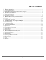
TABLE OF CONTENTS
1
1.1
1.2
2
2.1
2.2
3
3.1
3.2
4
4.1
4.2
5
5.1
5.2
5.3
5.4
6
6.1
6.2
6.3
6.4
6.5
6.6
System Introduction ............................................................................................................ 1
Technical Specification........................................................................................................... 1
ES550/ES551/EX550/EX551 System Block Diagram............................................................ 3
Firmware Upgraded Flow .................................................................................................... 4
Setup Tool/Equipment ............................................................................................................ 5
Upgrading Procedure............................................................................................................. 5
Machine Disassembly and Replacement ......................................................................... 16
Tools ................................................................................................................................... 16
Disassembly Procedure ....................................................................................................... 17
Troubleshooting and Verifying the Repair ....................................................................... 25
Troubleshooting ................................................................................................................... 25
Verifying the Repair ............................................................................................................ 31
Connector Information ...................................................................................................... 39
Main Board .......................................................................................................................... 39
The backside of mainboard.................................................................................................. 40
Ballast Board........................................................................................................................ 41
Power board......................................................................................................................... 41
FRU (Field Replaceable Unit) List..................................................................................... 42
Mechanical Drawing............................................................................................................. 43
Board/Module....................................................................................................................... 44
Case/Cover/Bracket Assembly............................................................................................. 44
Optical Device...................................................................................................................... 44
Fans..................................................................................................................................... 44
Speaker................................................................................................................................ 44
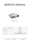
IV
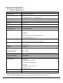
1 System Introduction
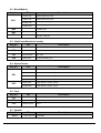
1.1 Technical Specification
Item
CONTENT
Display Type
Single 0.55” DLP panel
Resolution(Pixels)
ES550/ES551: SVGA (800x600pixels)
EX550/EX551: XGA (1024x768 pixels)
Lamp
180W
Zoom Ratio
1.1X
F/No.
1.97 - 2.17
Focal length
21.95 - 24.18mm
Screen size
30” - 300”
Projection Type
Front, Rear, Ceiling
Input Source
D-Sub 15-pin x 2,
S-Video x 1,
Video x 1,
Audio signal input (3.5mm stereo mini jack) x 1,
HDMI (ES551/EX551 only)
Output Source
D-Sub 15 pin x 1,
Audio signal output (3.5 mm stereo mini jack) x1
Control terminal
RS-232 x 1, Mini USB type x1 (supports firmware upgrade and remote
mouse control)
Speaker
2 watt x 1
Scanning frequency
Horizontal frequency
31 - 100 KHz
Vertical frequency
50 - 120 Hz
Power requirement
AC 100-240 V, 50 - 60 Hz, 2.6A
Power consumption
245 W (Max.)
Digital Keystone Correction
Vertical + / - 30。
Environment
Operating:
Temperature:0。C to 40。C
Humidity: 10-80% maximum
Storage:
Temperature: -20。C to 60。C
Humidity: 30-85%
Dimension (W x D x H)
282.9 x 231.1 x 94.7 mm
Weight
2.2 Kg
Note: Designs and specifications are subject to change without prior notice
1
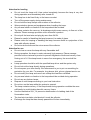
Attention for handing
Do not touch the lamp until it has cooled completely, because the lamp is very hot
during operation and immediately after turned off.
The lamp has to be fixed firmly to the base or socket.
Turn off the power supply during maintenance.
Do not hold the lamp except outer surface of the reflector.
Wear protective gloves and eyeglasses when handling the lamp.
Any unusual shock or vibration to the lamp should be avoided.
The lamp contains the mercury. Its breakage might cause mercury to flow out of the
reflector. Please manage provision at the customer’s product.
Do not pull the lead wire and plug by more than 24.5N.
Please be careful of handling the lamp because it is made of glass.
Please notice for keeping or handling the lamp, because there is a projection of this
lamp with reflector ahead.
Do not touch the bulb and the mirror area of the reflector.
Attention for use
Do not close or cover the lamp with any flammable stuff.
During operation, the lamp is under extremely high pressure. Please manage
provision at the customer’s product to prevent fragments of bulb and mercury from
flowing out of it. If the lamp bursts in case of an emergency, the sound will be
occurred.
Lamp operation should be with the specified lamp driver and the system only.
Do not look at the lamp directly during operations.
Do not expose your skin directly. We recommend to you to put on something for
protection for your skin. For example, long sleeve shirt, gloves, glassed and so on.
Do not modify the lamp and never use a lamp that has been modified.
Any unusual shock or vibration to the lamp should be avoided during operation.
Do not use any broken lamps.
Dispose of used lamps according to your local instruction.
Do not turn on the lamp while the system is opened.
The lamp contains mercury. If the lamp bursts during operation ventilate the area
sufficiently to avoid inhaling harmful mercury fumes.
Use the lead below 200℃ to prevent a deterioration of cladding clad of the
fluorocarbon resin.
The lead wire insulation clad shouldn’t touch the reflector.
Exchange the lamp that has already passed the life time immediately.
2
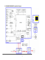
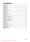
1.2 ES550/ES551/EX550/EX551 System Block Diagram
3
2 Firmware Upgraded Flow
This provides the information regarding relevant equipments and upgrading procedure for
firmware upgrade.
Purpose:
Flash Loader vX.X.exe flash loader is for upgrading image file to projector and is be designed to
execute on Windows 2000/Windows XP/Windows Vista/Win 7.
Note:
Please check the firmware version before any firmware upgrade procedures. During
firmware download period, please do not shut down PC or projector, this will cause flash
memory’s damage. And need to return the unit to manufacturer for flash memory recovery.
4
2.1 Setup Tool/Equipment
Computer
Power Cord
USB Cable
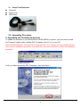
2.2 Upgrading Procedure
1) Upgrading the Firmware on the Unit
To update the firmware on your ES550/ES551/EX550/EX551 projector, you first need to install
the Firmware Update Utility software DPL Composer Lite v10.x.x on your PC.
Open Windows Explorer, locate the DLP Composer Lite v10.x.x Setup, and then double-click the
icon to launch installation procedure, and follow the on-screen instructions to finish the installation
procedure.
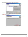
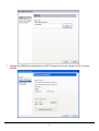
Verify you have opened the DPL Composer , then click Next >
5
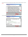
Once you have read the License Agreement and agree, select the I Agree radio button , then click
Next >.
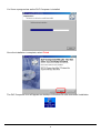
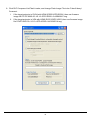
In the box of Readme Information, after read click Next>
6
Select which features you would like to install, and then click Next>
Click Next to begin installation
7
You’ll see a progress bar as the DLP Composer is installed
Once the installation is complete, select Finish
The DLP Composer Icon will appear on desktop of WindowsTM after successful installation.
8
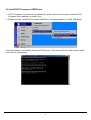
2) Install DLP Processor USB Driver
1. If DLP Composer Lite does not be installed yet, please follow the description of section DLP
Composer Lite Installation to install it first.
2. Please click the ”Install DLP Processor USB Driver” (as below graphic) to install USB Driver.
During installation, the installer will show a DOS screen. This screen will close itself and the install
will continue automatically.
9
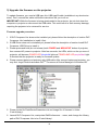
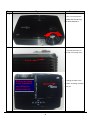
3) Upgrade the firmware on the projector
To update firmware, you need a USB type A to USB type B cable (available at any electronics
store). Don’t connect the cable until these instructions tell you to do so.
IMPORTANT! While the firmware is being downloaded to the projector, do not shut down the
computer or projector or disconnect the USB cable. This could result in flash memory damage,
requiring the projector to be returned for service.
Firmware upgrade procedure:
1. If DLP Composer Lite does not be installed yet, please follow the description of section DLP
Composer Lite Installation to install it first.
2. If USB Driver does not be installed yet, please follow the description of section Install DLP
Composer USB Driver to install it.
3. Please press and hold (do not release) both POWER and MENU/EXIT button of projector,
then connect AC power to projector. After few seconds, the LEDs, which on the up-cover of
projector, will become POWER LED blue/solid light and TEMP/LAMP LED purple/flash light.
It denotes that the projector is ready for firmware update.
4. Please connect laptop and projector with USB cable. After connect laptop and projector, you
may find Jungo\Texas Instruments DLPTM Processor at Device Manager of Windows OS.
5. Please locate file FlashDeviceParameters.txt and image file of firmware in folder
C:\dev\Library\.
6. Launch DLP Composer Lite, manipulate Edit\Preferences… menu, and change the Library
path of DLP Composer Lite to be C:\dev\Library\.
10
7. Change the USB Device Identification of DLP Composer Lite to be Vendor: 0x451, Product:
0x2000.
11
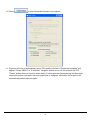
8. Click DLP Composer Lite\Flash Loader, and change Flash Image File to be C:\dev\Library\.
Comment:
I. If the target projector is SVGA with HDMI (ES551/OPD-S5001) then use firmware
image file PC337-9660-00--V0.10--OPD-S5000--0x10BA991C.img.
II. If the target projector is XGA with HDMI (EX551/OPD-X5001) then use firmware image
file PC437-9660-00--V0.10--OPD-X5000--0x10C86D1A.img.
12
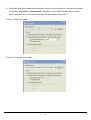
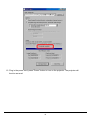
9. Select the Skip Boot Loader Area check box, when you do not want to overwrite boot loader
of projector, as picture 1 (recommend). Otherwise, do not select the Skip Boot Loader
Area check box, when you want to overwrite the boot loader, as picture 2.
Picture 1: Skip boot loader
Picture 2: Overwrite boot loader
13
10. Press
to start download firmware into projector.
11. Projector will turn on automatically when FW update is finished ("Download complete" will
appear). Press "MENU" or "4-direction" navigator button to turn off the projector (NOTE:
"Power" button does not function at this point). Cooling process (fans spinning) will then start.
Unplug the power cord when the cooling process is complete; otherwise, the projector will
automatically switch back on again.
14
12. Plug in the power cord, press "Power" button to turn on the projector. The projector will
function as usual
15
3 Machine Disassembly and Replacement
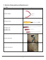
3.1 Tools
Item
Photo
Long Nose Nipper
Hex Sleeves 5mm
Screw Bit(+):107
Screw Bit(+):101
Screw Bit(+):102
Anti-static wrist strap
Anti-static wrist gloves
16
3.2 Disassembly Procedure
Warning
Put on the Static Electricity Ring when starting for repair.
Repair Environment suggest in Clean-room class 10000. Do not remove Optical
Engine or DMD panel outside the clean room. Please return the optical engine to
supplier if your repair condition can not meet the requirement.
While screwing or unscrewing screws, please keep the screwdriver straight. Keeping
screwdriver inclined will damage the screw holes.
Please turn off the power before replacing any parts.
Please wait for the projector lamp cooling down and turn off the power before changing
it. Never touch or hit the lamp module when replacing the lamp.
When you replace the projector lamp, never touch the new lamp with your bare hands.
The invisible residue left by the oil on your hands may shorten the lamp life. Use
lint-free gloves or finger cots are recommended.
17
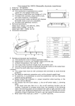
Step
Figure
Description
1
.
Shown you the projector.
Rotate the focus ring
left and remove it.
2
1. Unscrew the screw on
the side of the lamp cover.
Screw
2. Sliding the lamp cover
Sliding the lamp
cover rightward,
and lifting the
lamp cover off
forward, and lifting the lamp
cover off.
18
Step
Figure
Description
3
Disconnect the lamp
connecter as shown.
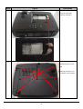
4
Flip the projector on the
table.
Removing screws x 8 on
the bottom cover as show.
Screws x 8
19
Step
Figure
Description
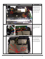
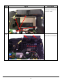
5
Lifting the top cover off
upward gently, disconnect
the front IR wire and the
safety switch wire then
remove the top cover.
6
Disconnect the two wires
and remove the ballast
module.
7
Remove the screws*5 on
the main board plate,
disconnect the two wires
and take the MB plate off
Screws*5
20
Step
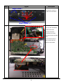
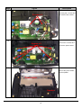
8
Figure
Description
Black Screw*1
Removing the screws on
the back cover as shown
Screws x 8
Black Screws x 3
9
Show you the main board
and the connectors.
Disconnect all wires
connected on the main
board and remove the main
board.
Please note there are 3
wires connect with the
behind of main board.
Behind of main board
21
Step
Figure
Description
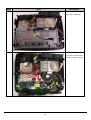
10
Remove the metal plate.
Metal plate
11
Unscrew the 3 screws and
remove the Optical Engine.
Screws x 3
22
Step
Figure
Description
12
Unscrew the 3 screws then
remove Fin outlet.
Screws x 3
Fan2
11
Remove the 2 Fan module.
2 Fan module
23
Step
Figure
Description
12
Removing the 2 screws and
Screws x 2
take off the Fan3 module.
13
Unscrew the 5 screws and
Screws x 5
remove the power board.
14
Remove the power holder
and the speaker.
Power holder
Speaker
24
4
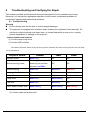
Troubleshooting and Verifying the Repair
This chapter provides technicians with electronic background how to maintain the product.
Moreover, you can get the appropriate operation to solve some complicated problems of
component repairing and professional problems.
4.1 Troubleshooting
Warning
Do not directly look into the lens to avoid eyesight damages.
The projector is equipped with ventilation holes (intake) and ventilation holes (exhaust). Do
not block or place anything near these slots, or internal heat build-up may occur, causing
picture degradation or damage to the projector.
Confirm Software and hardware
(1) Confirm lamp using hours
(2) Confirm LED indicator
The Status Indicator Panel on top of the projector indicates the state of the projector and can help
you troubleshoot.
Projector Status
POWER
TEMP
LAMP
Standby mode
Blue solid
Off
Off
Normal running mode
Flashing 30 seconds after
powering on and then
Off
become solid Blue
Off
Normal cooling
Blue solid
Blue solid
Red solid
Lamp ignition failed
Blue solid
Off
Red flashing
Lamp life end
Blue solid
Off
Red solid
Temp error
Blue solid
Blue flashing
Off
Fan error
Blue solid
Blue solid
Off
Color wheel or DMD error
Blue flashing
Blue flashing
Red flashing
(3) Confirm cable connection well.
25
Note: Swapping modules that may be defective with others known to be good is generally an ideal way to find the
module responsible for the problem. A failure symptom is rarely caused by more than one module, so you will not
usually need to replace more than one to correct a particular failure. Whatever main board, ballast, IR board,
power board, lamp module or optical engine are all suitable to check by swapping modules.
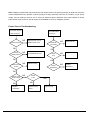
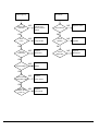
Power Source Troubleshooting:
No Power Source
Fan failure after
after turning on
turning on
NG
Check connector
Replug power cord or
Check fan
connection
replace power cord
OK
Check
Safety Switch
NG
Replace Safety Switch
or reinstall lamp cover
Check
Fan
OK
NG
Replace fan
NG
Replace
OK
NG
Replace button
Check
Mainboard
OK
Check 12 pin
Power output
Reconnect fan
OK
OK
Check LED and
button
NG
NG
Check
Fuse
NG
OK
Replace
Replace power
mainboard
board
Replace fuse
26
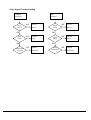
Mainboard
Fail to light up
Check LED
indication
No Volume
NG
Refer to LED
indicator and
follow indicative
actions
NG
Replace
Check
Speaker
Lamp Module
NG
Replace
Check
Mainboard
Mainboard
NG
Check Ballast
Replace
Ballast
OK
NG
Replace
Power board
OK
Check CW
Rotation while
power on
Replace
Speaker
OK
OK
Check Power
board 380V output
NG
OK
OK
Check
Mainboard
Replace button
Check button
OK
Check
Lamp
NG
NG
Replace
Color Wheel
27
NG
Replace
Mainboard
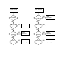
Video Signal Troubleshooting
Computer
Video
No Signal
No Signal
Check
Source
NG
Turn on
Check
Source
Source
OK
Check
Cable
Turn on
Source
OK
NG
Replace
Check
Cable
Cable
OK
Check monitor
out signal
NG
NG
Replace
Cable
OK
NG
Replace
Check
Mainboard
Mainboard
28
NG
Replace
Mainboard
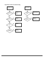
Image abnormal
Color abnormal
Power on again
and reset OSD
Check input cable
and signal setting
OK
Check input cable
and signal setting
NG
Adjust
Check Color
Wheel Index
Input signal
Input signal
NG
Adjust Color
Wheel Index
OK
NG
Replace
Check
Mainboard
Mainboard
OK
Check
Optical Engine
Adjust
OK
OK
Check
Mainboard
NG
NG
Replace
Mainboard
OK
NG
Replace
Check
Optical Engine
Optical Engine
29
NG
Replace
Optical Engine
Operation Function Troubleshooting
Button Failure
Remote Control
Failure
Check
Battery Level
NG
Replace
Check
button
Battery
OK
Check
Remote Control
NG
Replace
Check
Mainboard
Remote Control
NG
Replace
IR
OK
Check
Mainboard
Replace button
NG
Replace
OK
OK
Check
IR
NG
NG
Replace
Mainboard
30
Mainboard
4.2
Verifying the Repair
After repairing projector (Dissembling and assembling projector), Repair center should verify
the quality of repaired unit.
(1) Signal test (Each I/O can function normally)
Connect all connector to the jacks one after the other to check whether each channel can
project normally
I/O port
VGA In (SVGA/XGA)
Test Equipment
Standard Pattern generator (Ex. Quantum data)
Signal format
800*600
60Hz for ES550/ES551
1024*768 60Hz for EX550/EX551
I/O port
Audio input
Test Equipment
Connect audio input to audio output from video equipment
Signal format
480i
I/O port
Video input
Test Equipment
Video source device
Signal format
NTSC
I/O port
S-Video input
Test Equipment
S-Video source device
Signal format
NTSC
I/O port
HDMI(ES551/EX551 only)
Test Equipment
HDMI source device (DVD player)
31
(2) Operation test
Buttons operation
Button description
Test criteria
Power button
1. Touch “power” button and projector will switch on, and in standby
mode the LED should solid.
2. Touch the “power” button (Up & Down) should be sensitive
3. The LED indicator lighteness and uniformity normally
Menu/Enter
1. Touch Menu/Enter button can make projector function normally.
2. Touch the button (Up & Down) should be sensitive
3. The LED indicator lighteness and uniformity normally
4-way button
1. Mechanical motion (Up & Down) should be sensitive when touch the
4-way button.
2. Touch 4-way button button can make projector function normally.
3. The LED indicator lighteness and uniformity normally
Foot adjuster operation
Foot adjuster.
Foot adjuster button
Test criteria
Foot adjusters should stretch downward smoothly by rotate the foot
adjuster feet
Zoom ring and Focus ring
Ring
Test criteria
Zoom ring
Mechanical motion of rotating Zoom ring to the end of right and left by
hand should be free from getting stuck.
Focus ring
The feeling of rotating Focus ring to the end of right and left by hand
should free from seizing
32
(3) Image Quality
Projected image size: 60 inches (diagonal length)
Zoom ring: Adjust zoom ring to wide (Maximum projection size)
VGA
I/O port
Monitor In (SVGA/XGA/WXGA)
Test Equipment
Standard Pattern generator (Ex. Quantum data)
Signal format
800*600
60Hz for ES550/ES551
1024*768 60Hz for EX550/EX551
Projected image size
60” in diagonal length
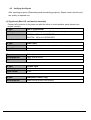
TOP SMPTE133
• Use to confirm overall image quality.
• Verify there is no noise, tint in the gray background, duplicated columns or other general
image abnormalities.
• No twinkling pixels allowed.
• Verify the 5% box is visible within the black square.
• Verify the 95% box is visible within the white square.
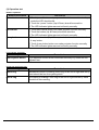
RGB Ramps
• Use to confirm correct colorwheel index delay setting and DMD data line integrity.
• Verify proper red, green, and blue chromaticity.
• Verify transition from dark to light in each ramp is smooth and consistent.
• Verify there are no missing parts (vertical black bars) of any ramp due to stuck bits.
• Verify there are no light or faded areas in ramps.
If there are colorwheel index delay is not correctly set.
33
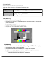
BLUE 120
• Use for dark blemish and ghost inspection.
• Confirm there are no more than four blemishes darker than Blue 120.
• No blemish greater than one inch or 25mm in length/diameter is allowed.
• Confirm there is no ghosting.
• No ghosting is allowed.
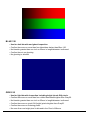
GRAY 50
• Use for light blemish inspection including bright (stuck ON) pixels.
• Confirm there are no more than four visible blemishes brighter than Gray50.
• No blemish greater than one inch or 25mm in length/diameter is allowed.
• Confirm there are no stuck ON (bright) pixels brighter than Gray50.
• Confirm there are no flickering pixels.
• No more than one bright pixel is allowed in the Pond of Mirrors.
34
WHITE
• Use for lumens and uniformity measurements, banding adjustment and inspection of
dark (stuck OFF) pixels, minor blemishes.
• Confirm there are no more than six total of light and dark blemishes
• Confirm no blemish is greater than five inches in length/diameter.
• Confirm there are no more than four stuck off pixels.
• Verify no banding.
If banding adjustment can’t completely eliminate banding use Banding Referee
image to make final determination.
BANDING REFEREE GRAY 245
• The goal is always to completely eliminate banding. If there still is a very small
amount of residual banding after the best banding adjustment has been made use
the Banding Referee to make final determination of acceptance.
35
Set UUT to Film gamma when using this image
• Distance from edge of image to Gray 245 band is 20 pixels.
• No banding appearing beyond the outer rectangle is allowed.
• No banding appearing darker than the Gray 245 band is allowed.
Both of the above two conditions must be satisfied for acceptance.
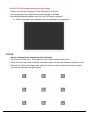
FOCUS
• Use to evaluate focus sharpness and uniformity.
• Focus on the center icon. Then adjust focus to achieve best overall focus.
• Verify all icons have clear resolution and white space can be seen between the green lines.
• Zoom to full Tele (small image) and verify all icons have clear resolution and white space
can be seen between the green lines.
36
Audio
I/O port
Audio
Test Equipment
Speaker &DVD player
Signal format
480i
Criteria
The audio out is normal
Video
I/O port
Video
Test Equipment
Standard Pattern generator (Ex. Quantum data)&DVD player
Signal format
NTSC
Criteria
No apparent color deviation on the projected image
S-Video
I/O port
S-Video
Test Equipment
Standard Pattern generator (Ex. Quantum data)&DVD player
Signal format
NTSC
Criteria
No apparent color deviation on the projected image
HDMI
I/O port
HDMI(ES551/EX551 only)
Test Equipment
HDMI source device, standard Pattern generator or DVD player
Criteria
No apparent color deviation on the projected image
(4) Resolution
I/O port
VGA
Test Equipment
PC
Test Method
1. Rotate Zoom ring to wide mode (Maximum projected image)
2. Fix projector to set diagonal length of projected image to 60”.
3. Adjust focus ring to make resolution of 4 corners and center
are balanced.
4. Check he characters should be recognized easily.
5. Rotate Zoom ring to tele mode (Minimum projected image)
6. Adjust focus ring to make resolution of 4 corners and center
are balanced.
7. Check the characters should be recognized easily.
37
(5) Front infrared sensor
Device
Front infrared
Test Equipment
Remote controller
Test method and Criteria
Operate remote controller to test front sensor is normal
(6) Brightness measurements
Test items
Brightness measurements
Test Equipment
Chroma automatic system (The alternative is CL-200)
Test method
Measure 9 points
Criteria
Marketing spec 20% off
(7) Safety test equipments
Test items
Safety test
Test Equipment
Safety analyzer
Test method
1. Clamp the metal shell of VGA connector
2. Plug the power cord to socket
Test criteria
GND 30A 3sec 100mΩ
DCW 2506V 1sec 10mA
Single Step OFF
38
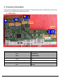
5 Connector Information
This section provides each connector location on boards and function of each board. They will be
useful for your detecting the defective boards.
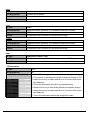
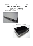
5.1 Main Board
No 05
No 07
No 04
No 06
No 02
No 03
Connector
Description
No 1
Safety switch
No 2
Thermal sensor
No 3
Fan3
No 4
Fan1
No 5
Color Wheel control
No 6
Front IR
No 7
Speaker
39
No 01
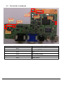
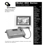
5.2
The backside of mainboard
No 03
No 02
No 01
No 05
No 04
No 06
Connector
Description
No 1
/
No 2
Connect to DMD Board
No 3
Fan2
No 4
Color Wheel Sensor
No 5
Connect to Power Board
No 6
Ballast control
40
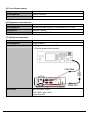
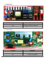
5.3 Ballast Board
No 3
No 1
No 2
Connector
Description
No 1
Lamp power supply
No 2
Ignite signal connected to Mainboard
No 3
Power supply
5.4 Power board
No 3
No 1
No 2
Connector
Description
No 1
AC Input
No 2
Ballast Power Supply
No 3
Connect to Main Board
41
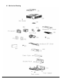
6 FRU (Field Replaceable Unit) List
Introduction
This section is a list of all the FRU removal. Following the FRU table of contents is an enlarged
view of the entire projector, which shows the primary FRUs in the projector.
When working on the projector, use appropriate anti-static precautions such as anti-static mats,
wrist straps and grounded work surfaces. Failure to do this can destroy static-sensitive
components and make the product inoperable.
42
6.1 Mechanical Drawing
43
6.2 Board/Module
Key No.
P/N
Description
PA784-7100
ES550_MAIN_DIP_PCB
PA884-7100
EX550_MAIN_DIP_PCB
PC384-7100
ES551_MAIN_DIP_PCB
PC484-7100
EX551_MAIN_DIP_PCB
B02
PA884-8100
POWER_ASY
B03
PA884-9000
BALLAST_ASY
B04
PA884-7500
FIR_DIP_PCB_ASY
B01
6.3 Case/Cover/Bracket Assembly
Key No.
P/N
Description
C01
PA884-4540
LAMP-COVER_ASY
C02
PA884-4500
TOP-COVER_ASY
C03
PA134-4540-99
C04
PA884-4510
KEY_ASY
BOTTOM-COVER_ASY
6.4 Optical Device
Key No.
O01
O02
P/N
Description
PA784-2200
OPTICAL ENGINE SIMPLE_ ES550
PA884-2200
OPTICAL ENGINE SIMPLE_ EX550
PC384-2200
OPTICAL ENGINE SIMPLE_ ES551
PC484-2200
OPTICAL ENGINE SIMPLE_ EX551
PA884-2400
LAMP MODULE_ES550_EX550
PC484-2400
LAMP MODULE_ES551_EX551
6.5 Fans
Key No.
P/N
Description
F01
02394-0151-00
FAN.1
F02
02394-0150-00
FAN 2
F03
02394-0152-00
FAN 3
6.6 Speaker
Key No.
SP01
P/N
02413-0117-00
Description
SPEAKER
44