1
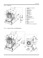
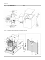
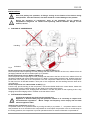
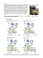
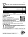
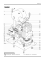
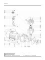
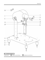
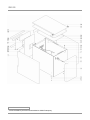
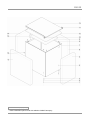
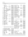
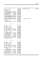
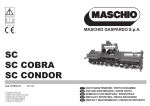
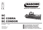
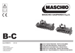
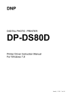
DK50 Kompakt 5/10 SERVICE MANUAL DK-50 CONTENTS DESCRIPTION OF PRODUCT ............................................................................................................................3 1. USAGE ACCORDING TO ASSIGNATION .............................................................................................3 2. TECHNICAL DATA ..................................................................................................................................3 3. CONDITIONS FOR USAGE ....................................................................................................................3 4. DESCRIPTION OF THE FUNCTION: .....................................................................................................4 INSTALLATION ...................................................................................................................................................7 5. PLACING OF COMPRESSOR ................................................................................................................7 6. PUTTING INTO OPERATION .................................................................................................................7 7. WIRING DIAGRAMS ...............................................................................................................................8 MAINTENANCE ...................................................................................................................................................9 8. MAINTENANCE INTERVAL ..................................................................................................................9 9. CONDENSATE DRAIN DOWN ...............................................................................................................9 10. CONTROL OF SAFETY VALVE..............................................................................................................9 11. REPLACEMENT OF INPUT FILTER.......................................................................................................9 12. REPLACEMENT OF FILTER IN AIR DRYER .......................................................................................10 13. REPLACEMENT OF FILTER IN CONDENSATION AND FILTRATION UNIT .....................................10 14. TROUBLESHOOTING...........................................................................................................................10 SPARE PARTS ..................................................................................................................................................11 Edition 3 SM-DK50-GB-3 -2- 10/2008 DK-50 DESCRIPTION OF PRODUCT 1. USAGE ACCORDING TO ASSIGNATION Dental compressors DK50 Z and DK50-10 Z - with base that allows autonomous setting of the compressor in a space. Dental compressors DK50 Z/K and DK 50-10 Z/K - with base and equipped by condensation and filtration unit (KJF1). Dental compressors DK50-10 Z / M - with base and equipped by adsorption air dryer. Dental compressors DK50 S and DK50-10 S - in compact boxes with efficient suppression of noise, suitable for placing in doctor’s office. Dental compressors DK50 S/K and DK50-10 S/K - in compact boxes and equipped by condensation and filtration unit (KJF1). Dental compressors DK50-10 S/M - in compact boxes and equipped by adsorption air dryer. 2. TECHNICAL DATA 10% Compressor efficiency at over-pressure 0,5 MPa.: 75 l min Air tank filling time from 0 to 0,6 MPa: DK50 Z (S) max. 25 s DK50-10 Z (S) max. 45 s DK50-10 Z/M (S) max. 55 s 230 V ( 50 Hz ) / 3,4 A Nominal voltage ( frequency ) / current: 230 V ±10 % ( 60 Hz ) / 4,3 A (at over-pressure 6bar) 110 V ( 60 Hz ) / 8,6 A (with dryer + 0,2A) Working pressure of compressor: 0,45 - 0,6 MPa 10% Safety valve - opening pressure: 0,8 MPa Operation mode: DK50 S, DK 50-10 S continual S1 continual S1 DK50 Z, DK 50-10 Z intermittent S3 - 50 % DK50-10 Z/M, DK50-10 S/M Capacity of air tank: DK50 5 lit. DK50-10 10 lit. Weight of compressor: DK50 Z 34 kg DK50-10 Z 36 kg DK50 S 46 kg DK50-10 S 49 kg DK50-10 Z/M 47 kg DK50-10 S/M 64 kg DK50 Z 290x430x490 DK50-10 Z 330x430x530 Dimensions: wxlxh (mm) DK50 S 380x525x575 DK50-10 S 420x525x620 DK50-10 Z/M 330x580x570 DK50-10 S/M 420x675x620 Compressor is made as the equipment of B type in I. category in accordance with standard STN EN 60 601-1. -1 3. CONDITIONS FOR USAGE Appliance can be installed and operated only in dry, well ventilated and dust-free areas, where ambient temperature is within the range of +5°C to +40°C and relative air humidity does not exceed 70% and absolute humidity below 15g/m3. Compressor must be installed so that it was well accessible for operating and maintenance and so that appliance label was accessible. Appliance must stand on flat, sufficiently stable base (take care after the weight of compressor, see paragraph 2. Technical data) Compressors cannot be exposed to outdoor environment. The appliance cannot be in operation in moist or wet environment. It is forbidden to use the equipment in the premises with presence of explosive gases, dust or combustible liquids. Before installing the compressor into the medical equipment, the supplier shall assess what medium – air, made available, would suit the requirements of the given purpose of usage. Respect technical data of the product for this purpose. At building-in, classification and evaluation of compliance must be performed by manufacturer – supplier of final product. Any other usage or usage over the given range is not considered to be the usage according to assignation. Manufacturer is not liable for damages implied from this. The risk is born only by operator / user. 10/2008 -3- SM-DK50-GB-3 DK-50 4. DESCRIPTION OF THE FUNCTION: Compressor (Fig.1) Aggregate of compressor (1) sucks in the free air through a line filter (8) and compresses it through a reverse valve (3) into an air tank (2). The apparatus draws the compressed air from the air nozzle, whereby the pressure drops to closing pressure set on the air-pressure switch (4), at which the compressor is switched on. The compressor again compresses the air into the air nozzle up to the value of cutoff pressure when the compressor is switched off. The safety valve (5) prevents the pressure excess in the air nozzle to above max. of 8 bars. The release valve (7) releases the condensate from the air nozzle. Such compressed and clean air free from oil traces is in air chamber ready for further usage. Compressor with dryer (Fig.2 , Fig.3) Aggregate of compressor (1) sucks in the free air through a line filter (8) and it is delivered into the air dryer in compressed form. The air proceeds through the cooler (15) through the dryer chamber (9) with adsorption apparatus (16), where the humidity is captured through a built-in filter (17) and reverse valve (3) as dried and clean air into the air tank (2). The adsorption apparatus is automatically regenerated in the regeneration cycle after each compressor switching off by the air-pressure switch. The adsorption chamber is depressurized through an open solenoid valve (14) at its simultaneous blowing-through with dried air. The adsorption apparatus is regenerated and the captured water from the chamber is displaced through the valve out. Compressed, dry and clean air free from oil traces is in air chamber ready for further usage. Additional dryer regeneration (without case) At a regular compressor operation with dryer, it is necessary to regenerate additionally the drying unit twice a month by opening the valve for additional regeneration (19) for a period of around 8 hours. During this time, the dryer filling shall regenerate constrainedly, whereby its high efficiency shall be provided for during the entire dryer lifetime. After the time of compulsory regeneration it is necessary to close the regeneration valve. Additional dryer regeneration in a case (Fig.3) For the compressor with a dryer MONZUN M1.10 in a case, the valve operation for regeneration (19) is led out through a flexible spindle to the front panel of the case. At regular compressor operation with dryer it is necessary to additionally regenerate the dryer unit twice a month by opening the valve for additional regeneration – by turning the button (21) from position "0" to the position "I" to the left (counter-clockwise) for a period of around 8 hours. After the time of compulsory regeneration it is necessary to close the regeneration valve by turning the button from position "I" to the position "0" (clockwise). Compressor with condensation and filtration unit (Fig.4) Aggregate of compressor (1) sucks in the free air through a line filter (8) and compresses it through a reverse valve (3) into an air tank (2). The compressed air from the air nozzle is led through cooler (10), which cools the compressed air; it captures the condensed humidity in the filter (11) and automatically separates as a condensate (12). Compressed, dried and clean air free from oil traces is ready for further usage. Compressor box Box ensures compact coverage of compressor and thus noise is effectively suppressed and at the same time a sufficient exchange of cooling air is ensured. Thanks to its design, it is suitable for placing in doctor’s office as a part of furniture. The fan blower under the compressor aggregate provides for compressor cooling. After a longer compressor activity the temperature in the case may increase above 40°C, when the cooling fan blower automatically turns on. After cooling the case area under around 32°C, the fan blower turns off automatically. The fan blower is also under operation together with the compressor engine. It is forbidden to create obstacles for entering of cooling air into the case (on the periphery of the case bottom part) and for the hot air outlet in the upper back part of the case. In the case of placing the compressor onto a soft floor, such as carpet, it is necessary to create a spacing between base and floor or box and floor, e.g. underlay the footings with hard pads., due to the provision of good compressor cooling. SM-DK50-GB-3 -4- 10/2008 DK-50 Fig.1 – Compressor 1. 2. 3. 4. 5. 6. 7. 8. 9. 10. 11. 12. 13. 14. 15. 16. 17. 18. 19. 20. 21. Aggregate of compressor Air tank Check valve Pressure switch Safety valve Manometer Release valve Input filter Dryer chamber Pipe cooler Filter Condensed outlet Solenoid valve Solenoid valve of dryer Cooler Adsorber Filter Sieve Valve for regeneration Stopper Button for valve of regeneration Fig. 2 - Compressor with air dryer MONZUN-M1.10 10/2008 -5- SM-DK50-GB-3 DK-50 Fig. 3 - Dryer MONZUN-M1.10 - Box Fig. 4 - Compressor with condensation and filtration unit KJF1 SM-DK50-GB-3 -6- 10/2008 DK-50 INSTALLATION Prior first putting into operation, all fixings serving for the fixation of the device during transportation must be removed, else there would be a risk of damage to the product. During the operation of compressor, parts of the aggregate can be heated to temperatures dangerous for contact with operating staff or material. Danger of fire! Caution, hot air! 5. PLACING OF COMPRESSOR Handling X Y Fig.5 Unfixation Dental compressor with a base DK50 Z, DK50-10 Z, DK50-10 Z/M (Fig.5) Place the product after unpacking from the package with the base to the floor of the room, release it from all packaging material and remove fixation parts (X,Y)- detail A. Dental compressor in a box DK50 S, DK50-10 S Place the product after unpacking from the package with the base to the floor of the room, release it from all packaging material and remove fixation parts (X,Y)- detail A. Direct output pressure hose, sludging hose and power cord in the back part of the compressor out of the compressor. Slide box from above to compressor so that front face is directed towards a front part of the compressor and box stuffing fixes the base at its circumference. Dental compressor in a cabinet DK50-10 S/M (Fig.3) From the top, put the housing on the compressor, connect the flexible shaft to the control button, fasten with the screw and cover the cabinet housing by the upper lid according to the picture. Check whether pressure hose, sludging hose and electric cord are duly lead via rear opening at box. Grip sludging hose with sludging valve in a holder at the rear side of a box. 6. PUTTING INTO OPERATION Connect the network rope fork into the network plug. Appliance is delivered with plug with protective contact. It is necessary to respect local electrotechnical regulations. Mains voltage and frequency must comply with the data stated at appliance label. Switching the compressor on (Fig.6) Compressor switch on at pressure switch by turning the shift (3) to position “I” , compressor starts to work and pressurize air to air chamber.At the compressed air consumption the pressure in the air nozzle drops to the closing pressure, the compressor in put into operation and the air nozzle is filled with compressed air. 10/2008 -7- SM-DK50-GB-3 DK-50 After reaching the cutoff pressure the compressor turns off automatically. After releasing – pressure decreasing in the air nozzle and reaching the closing pressure, the compressor is again put into operation. Check this value of pressure at manometer (5). Setting of switching or switching-off pressure can vary within the range of i 10%. Air pressure in air chamber must not exceed maximal permitted operation pressure. After a longer compressor activity the temperature in the case increase above 40°C, when the cooling fan blower automatically turns on. After cooling the case area (in the ambient of compressor) under around 32°C, the fan blower turns off automatically. The fan blower is also under operation together with the compressor engine. 3 2 1 5 4 Fig.6 It is not allowed to tamper and change pressure limits of pressure switch at compressor Pressure switch (2) was adjusted by manufacturer. 7. WIRING DIAGRAMS D K 50 Z, D K50-10Z, D K 50 S, D K50-10S D K50 Z, D K 50-10Z, D K50 S, D K50-10S 1/N /P E ~ 230 V 50..60 H z E LE C T R IC O B JE C T O F 1st C A T. B TY PE 1/N /P E ~ 115 V 60 H z E LE C T R IC O B JE C T O F 1st C A T. B TYP E ST ST SP SP M Z1 M p> 40 °C p> 4 0°C Z1 U1 U1 15 0°C 1 50 °C PE Z2 U2 2 1 PE 3 PE ST SP M EV1 U N U U2 2 1 X1 1 2 3 X2 4 N U N U X1 1 2 3 X2 4 C B1 EV 1 YV 1 Therm o sw itch P ressure sw itch M otor of com pressor Fan of com pressor PE Y V1 C b1 FU X 1, X 2 S olenoid valve C apacitor Fuses , T10A Term inal ST SP M EV1 C B1 EV1 Therm o sw itch P ressure sw itch M otor of com pressor F an of com pressor YV 1 C b1, C b2 FU X 1, X 2 D K 50-10Z/M , D K 50-10S/M D K 50-10Z/M , D K 50-10S/M 1/N /P E ~ 115 V 60 H z E LE C T R IC O B JE C T O F 1st C A T. B TY P E ST SP ST M p> U1 SP Z2 U2 2 1 M Z1 U1 Z2 U2 2 1 1 50 °C PE 15 0°C PE 3 FU PE ST SP M EV1 EV2 N U N U X1 3 FU 1 2 3 4 X2 N U N U X1 1 2 3 4 X2 C EV 1 Therm o sw itch P ressure sw itch M otor of com pressor F an of com pressor F an of dryer SM-DK50-GB-3 S olenoid valve C apacitor Fuses,T16A Term inal p> 40 °C Z1 C B2 Y V1 1/N /P E ~ 230 V 50..60 H z E LE C T R IC O B JE C T O F 1st C A T. B TYP E 4 0°C 3 FU FU N Z2 EV 2 Y V1 Y V1 C b1 FU X 1, X2 PE S olenoid valve C apacitor Fuses,T10A Term inal ST SP M EV1 EV2 -8- C B1 E V1 Therm o sw itch P ressure sw itch M otor of com pressor Fan of com pressor Fan of dryer E V2 C B2 YV 1 YV1 C b1, C b2 FU X1, X 2 Solenoid valve C apacitor Fuses,T16A Term inal 10/2008 DK-50 MAINTENANCE Prior every work at maintenance or repair, switch off the compressor and disconnect it from mains. 8. MAINTENANCE INTERVAL Maintenance that must be performed Chapter • Release condensate Compressor without air drier At high air humidity Compressors with air drier 9 Compressors with condensation unit : - from filter - from pressure vessel • Control safety valve 10 • Replacement of input filter 11 • Replacement of filter and checking of the filling in 12 drier • Replacement of filter in condensation unit 13 • Control of tightness of joints and Service control examination of device documentation Time interval Performed by 1 x week operating staff 1 x day operating staff 1 x week, control the function operating staff 1 x week, control the function 1 x week 1 x year 1 x of 2 years 1 x year operating staff operating staff qualified expert qualified expert qualified expert 1 x year 1 x year qualified expert qualified expert In order to find out correct work of compressor, it is necessary, in certain intervals (Chapter 8) to perform the following activities: 9. CONDENSATE DRAIN DOWN Compressors (Fig.7) In the case of operation, it is recommended to release condensate from pressure tank 1 x week (at high air humidity 1 x day). Switch off the compressor from mains and reduce air pressure in the device to pressure of max. 1 bar, for example by releasing air via connected device. Canalize hose with sludging valve to vessel prepared in advance. By opening the release valve (1) release condensate from tank. Wait till condensate is fully delivered from pressure tank.Again close release valve (1). 1 Fig.7 Compressors with condensation and filtration unit. (Fig.10) In the case of operation, condensate is automatically released via release valve of condensation unit filter. Perform the control of the function of automatic sludging as follows: Open valve (4) of sludging vessel (2) by unscrewing to left, release small amount of condensate from the vessel. Close valve (4) again by screwing to right, thus automatic mode of sludging is adjusted. Compressors with air dryer In the case of operation, condensate is automatically released via outlet solenoid valve of air dryer. 10. CONTROL OF SAFETY VALVE Safety valve must not be used for depressurizing of pressure tank. It could endanger the function of safety valve. It is adjusted to permitted maximal pressure by manufacturer, it is tested and marked. It must not be readjusted. Warning ! Compressed air may be dangerous. You may have to protect your sight when blowing air out. Its impediment may occur. (Fig.6) At the compressor is put into operation for the first time, it is necessary to control correct function of safety valve. Turn screw (4) of safety valve (1) several rotations to left till safety valve blows out. Let safety valve blow out only for a short time period. Turn screw (1) to right till backstop, valve must be closed now again. During this control, pressure tank must be under pressure of max. 6 bars. 1 2 11. REPLACEMENT OF INPUT FILTER (Fig.8) It is necessary to exchange the filter insert every two years (1), located in the lid of the compressor engine case. Take out rubber plug by hand (2). Take out dirty filter insert take out. Put inside a new filter insert and cover it with rubber plug 10/2008 -9- Fig.8 SM-DK50-GB-3 DK-50 12. REPLACEMENT OF FILTER IN AIR DRYER (Fig.9) Replace filtration pad in the upper part of drying box once a year. Remove the dryer plug (1) by unscrewing to the left on the body(4). Change the filter (2). Put a plug to the body (4) and tighten it to right. Fig.9 13. REPLACEMENT OF FILTER IN CONDENSATION AND FILTRATION UNIT ( Fig.10) In the case of a regular operation of condensation unit, it is necessary to replace filtration pad in filter with automatic sludge drain once a year. Loosen fuse (1) at filter by pulling it down and turn the cover of filter (2) to left and pull it out. Unscrew filtration pad (3) by turning it to left. Replace filtration pad and screw the new one by turning to right back to the body of filter. Put on the cover of filter and secure it by turning to right till safety pin locks. Fig.10 14. TROUBLESHOOTING Manufacturer reserves the right to make changes on the appliance that however will have no impact on substantial characteristics of the appliance. Prior the intervention to the appliance, it is necessary to reduce chamber to zero and disconnect the appliance from mains. air pressure in air Activities regarding troubleshooting can be performed only by qualified service expert. Fault Compressor does not start Compressor often switches on without air consumption Symptom and possible causes Repair a/ No power supply b/ Power supply is interrupted - flexible cord is cut off - loose clip - motor winding is cut off - thermal protection is damaged - check clips and pressure switch function - damaged solenoid. valve c/ High current consumption - check capacitors - difficult mechanical run, piston crash - damaged winding of a motor a/ Air section leakage b/ Compressor leakage a/ check fuses, replace damaged ones b/ - replace damaged part - tighten clips - replace el. motor - replace el. motor - tighten clips or replace pressure switch - Replace solenoid. valve c/ - replace damaged capacitor - replace damaged piston and/or cylinder - replace motor a/ check connections, seal leaking ones b/ check connections by e.g. soap water, seal leaking ones, replace damaged „O“ring, test, dismount and clean return valve a/ - replace damaged bearing - put loose spring back, replace damaged one a/ replace element b/ replace worn-out piston rings - replace gasket, tighten head Compressor is noisy a/ Knocking or other metal sounds - bearing is damaged - Loosen (cracked) crush element (spring) Efficiency is decreased, work cycle of compressor is extended SM-DK50-GB-3 a/ polluted suction filter element b/ low unit performance - gasket between head, cylinder and valve plate damaged - 10 - 10/2008 DK-50 SPARE PARTS - Compressor DK50 L - Bonded joints – adhesive LOCTITE 270 10/2008 18* - valid till ser.num. – E-4725-09-08 - 11 - SM-DK50-GB-3 DK-50 A Aggregate DK50 L - Bonded joints – adhesive LOCTITE 620 SM-DK50-GB-3 2* - valid till ser.num. - E-4725-09-08 - 12 - 10/2008 DK-50 B Air tank complete Bonded joints 10/2008 L – adhesive LOCTITE 270 L1 – adhesive LOCTITE 243 - 13 - SM-DK50-GB-3 DK-50 C Box DK50-10 / M - Noise insulatation pad to bond with adhesive SABA Foamspray SM-DK50-GB-3 - 14 - 10/2008 DK-50 D-E Box (5L) - (10L) - Noise insulatation pad to bond with adhesive SABA Foamspray 10/2008 - 15 - SM-DK50-GB-3 DK-50 - DK50Z(S) - (5l) DK50-10Z(S) - (10l) 1 Hose output 4BA-013 -Hose 5000 -Clamper -Tapered element 6 4KB-062 -Nut 4KB-063 2 Washer D4,1 3 Screw M4x8 4 Electric board compl. 4CA-059 5 Fuse T 10A (230/50-60Hz) Fuse T 16A (110/50-60Hz) 6 Electric board housing 4KA-127.1 7 Tightening strap 140x3,6 8 Washer M3x35 9 Screw D3,2 10 Drain valve G ¼“ 11 Drain hose 12 Screw M5x16 13 Washer flexible D5,1 14 Clip 4KA-192 - Isolation pipe 110 15 Damping element S 4CA-215 16 Screw M6x60 17 Washer warning 18 Fixation element 3KC-424 18* Fixation element 19 Nut M8 20 Washer D8,4 21 Damping element H 4CA-216 22 Fan 230V Fan 110V 23 Fan housing 3KB-914 24 Fan Screw M4x45 25 Safety valve 4BA-025 26 Gasket CU 4KA-078 27 Manometer 50 G ¼ 28 Silencer G 1/8 29 Solenoid valve 30 Input hose D8x300 31 Thermo switch 40°C 32 Washer A 604011013 062000117 049000010 024000122 024000118 043000003 041000006 604021059 038100005 038100007 062000003 069000024 043000015 041000004 025300001 072000012 041000087 043000005 023000112 034800131 604021215 041000503 062000366 062000447 023000607 042000006 043000009 604021216 035300006 035300005 062000347 041000502 604011025 025900003 025400003 025400018 036100022 072000039 033510004 043000017 Aggregate DK50 230/50 1BA-511 601011511 Aggregate DK50 230/60 1BA-567 601011567 Aggregate DK50 110/60 1BA-568 601011568 A1 Motor complete 230V/50-60Hz Motor complete 110V/60Hz A1a Condensator 30MF/450V(230V) Condensator 2x60 MF/450V(110V) A2 Holder central 3KC-417 A2* Holder central 3KB-996 A3 Nut M8 A4 Washer D8,2 A5 Washer D8,4 A6 Screw M8x25 A7 Side left 3KB-912 A8 Side right 3KB-911 SM-DK50-GB-3 035110008 035110015 031330003 031330010 023000776 023000579 042000006 043000017 043000009 041000511 062000346 062000345 A9 A10 A11 A12 A13 A14 A15 A16 A17 A18 A19 A20 A21 A22 A23 A24 A25 A26 A27 A28 A29 A30 A31 A32 A33 Crank case 3KB-834 Screw M8x16 Crank 50Hz 4CA-195 Bearing 6304 Screw M6x25 Piston with piston rod 4CA-194 Membrane screw 4KA-016.1 Membrane 4KA-031.1 Piston ring el. Washer flexible D5,1 Socket screw M5x30 Sealing liner 4KB-892 Crank case cap 4KB-835 Screw M4x10 Filter element 03 Suction plug 3KB-893 Cylinder 4KB-832 O-ring D50x2 Valve plate 4CA-023 Membrane seat 3KA-015 Pressure spring 4KA-019C Cylinder head complete 4CA-208 Washer flexible D6,1 Screw M6x110 Fitting G3/8MM 050000033 041000051 604021195 021000026 041000115 604021194 024000007 024000008 069000123 043000005 041000036 074000065 050000034 041000110 025200126 074000064 050000036 073000109 604021023 024000006 022000010 604021208 043000007 041000045 025400119 B Airtank complete - 5L 2BA-520 Airtank complete - 10L 2BA-518 602011520 602011518 B1 Air tank 5l 2CA-219 602021219 Air tank 10l 2CA-213 602021213 B2 Plug M30x1,5 4KA-953 024000247 B3 Base plate 5l 3KB-954 023000567 Base plate 10l 3KB-909 023000534 B4 Rubber legCM-2207 074000010 B5 Washer 5,3/15 043000101 B6 Screw M5x25 041000208 B7 Pressure switch 4DA-061 604031061 B8 Connecting Nut 4KA-103 024000027 B9 Gasket Cu 4KA-104 025900004 B10 Fitting block to press.switch4KA-642 024000101 B11 Pressure switch pipe 4KA-765 024000357 B12 Securing nut M12 4KA-180 024000162 B13 Non-return valve 025300007 B14 Fitting MF 3/8 025400034 B15 Fitting ¼ modif. 4KB-066 024000311 C Box C1 C2 C3 C4 C5 C6 C7 Screw M4x12 Washer 4.3 Rubber leg Nut 4 Valve control 3BA-558 Noise insulatation pad 4KC-254 Noise insulatation pad 64x58,4x5 - 16 - DK50-10 / M 3BA-557 603011557 041000007 043000019 074000004 042000002 603011558 062000410 061000260 10/2008 DK-50 C8 Lower case compl. 3CA-239 C9 Pin M4 C10 Pin spring M4 C11 Washer 4 C12 Noise insulatation pad 53x32x2 C13 Noise insulatation pad 4KC-259 C14 Capping strip left 4KC-125 C15 Capping strip right 4KB-983 C16 Upper plate 3KC-140 C17 Noise insulatation pad 31,8x5x2 C18 Noise insulatation pad 41,x11,5x3 C19 Noise insulatation pad 41,5x3x2 C20 Noise insulatation pad 30x3x3 C21 Noise insulatation pad 4KC-256 C22 Tunnel for ventilator 4KC-143 C23 Rivet - Washer 4.3 C24 Noise insulatation pad 4KC-257 603021239 049000154 049000155 043000003 061000255 062000413 062000399 062000400 023000649 061000256 061000259 061000254 061000258 062000411 023000652 044000012 043000019 062000412 D 603011014 Box (5L) 3BA-014 D1 D2 D3 D4 D5 D6 D7 D8 Screw M4x12 Washer 4,3 Rubber leg CM 4144 Nut M4 Noise insulatation pad Noise insulatation pad Lower case Rivet 4x9.5x12 Washer 4,3 D9 Noise insulatation pad C10 Capping strip left C11 Capping stri right D12 Noise insulatation pad D13 Upper plate D14 Noise insulatation pad D15 Noise insulatation pad D16 Fastclip 656-111 E Box E1 E2 E3 E4 E5 E6 E7 E8 4KA-137 4KC-125 4KB-983 4KA-529 3KA-203 4KA-135 4KA-198 (10L) 3BA-115 Screw M4x12 Washer 4,3 Rubber leg CM 4144 Nut M4 Noise insulatation pad Noise insulatation pad Lower case Rivet 4x9.5x12 - Washer 4,3 E9 Noise insulatation pad C10 Capping strip left C11 Capping strip right E12 Noise insulatation pad E13 Upper plate E14 Noise insulatation pad 10/2008 4KA-134 4KA-136 2KA-133 4KA-532 4KA-534 2KA-343 4KA-535 4KC-125 4KB-983 4KA-537 3KA-344 4KA-533 E15 Noise insulatation pad 4KA-536 E16 Fastclip 656-111 061000045 033400013 * ) – valid for older version 041000007 043000019 074000004 042000002 061000018 061000056 023000259 044000012 043000019 061000057 062000399 062000400 061000058 023000128 061000019 061000025 033400013 603011115 041000007 043000019 074000004 042000002 061000037 061000059 023000258 044000012 043000019 061000060 062000399 062000400 061000061 023000131 061000038 - 17 - SM-DK50-GB-3 EKOM spol. s r.o. Priemyselná 5031 / 18 921 01 PIEŠŤANY Slovenská republika tel.: +421 33 7967255 fax: +421 33 7967223 e-mail: ekom @ ekom.sk