1
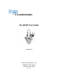
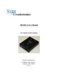
Mr. SQUID User’s Guide
Building an Analog Flux-Locked Loop *
7.2
Purpose and Background
While the periodicity of the voltage modulation of a current-biased SQUID is 1 flux quantum
(Φ0 ~ 2×10-15 Wb), this is not the limiting resolution of magnetic flux measurement using a
SQUID. As mentioned in the SQUID Operation section of Section 5, one can, using appropriate
electronics, measure changes far smaller than 1 flux quantum. Low-temperature SQUIDs can
quite typically measure magnetic flux changes down to millionths of a flux quantum. But in
addition to requiring high sensitivity, most experiments in which one would use a SQUID also
require considerable dynamic range. In other words, one does not need merely to detect a small
magnetic flux; one may also need to measure a sizable magnetic flux with sub-flux-quantum
accuracy. The way one does this is to operate a SQUID in what is called a “flux-locked loop.”
A flux-locked loop functions in a straightforward way. One biases the SQUID with a constant
current so that the voltage across the SQUID will be periodic with the applied flux (such as is
done in the V-Φ setting on the Mr. SQUID® box). One then amplifies this voltage response and
uses the resultant signal to drive a coil near the SQUID. The system is set up in such a way that
the current flowing through the coil creates a magnetic flux of opposite polarity to the unknown
flux to be measured. If one sets up the system correctly, the SQUID will be in a zero magnetic
flux condition - in fact, it will be “locked” onto a zero-flux condition. Under the flux-locked
condition, one only has to measure the current being used to generate the opposing flux in order
to determine the magnitude of the unknown flux. This scheme is called a “flux-locked loop”.
How accurately one can create the opposing flux is limited by factors like the noise of the
SQUID and the noise of the electronics. Ideally, one can match the opposing fluxes to within a
very small fraction of a flux quantum. In the experiment outlined below, you will use the
external field coil on the Mr. SQUID® chip to set up a flux-locked loop.
Equipment
•
For this experiment you will need:
•
Mr. SQUID® and liquid nitrogen
•
An oscilloscope
•
A solderless breadboard 25
•
Three general-purpose operational amplifier chips (e.g., 741)
•
Two 9-Volt transistor batteries
•
One 10 kΩ potentiometer
•
A selection of resistors in the range of 1 kΩ through 100 kΩ
•
A selection of capacitors in the range of 0.001 µF through 1 µF
•
A selection of hook-up wire and “alligator clips”
*Advanced experiment 7 is building a digital flux-locked loop.
25Such
®
as Radio Shack part numbers 276-169, 276-174, 270-175.
STAR Cryoelectronics, LLC
62
Mr. SQUID User’s Guide
A simple flux-locked loop circuit that can be used with your Mr. SQUID® is shown in Figure
7-6. This circuit will allow you to measure magnetic fluxes imposed on Mr. SQUID® down to
about 0.1 Φ0. In the ideal case, your Mr. SQUID® system can be used to measure fluxes as small
as about 0.001 Φ0 (a limit set by the electronics in the control box). This experiment falls far
short of limiting performance because the circuit illustrated was designed for simplicity rather
than performance. It can easily be built by students with little or no training in electronics. The
integrated circuits were chosen to be inexpensive and readily available. In the illustrations that
follow, the integrated circuits were LM1458 dual op-amps available from most electronics parts
stores 26 . We suggest that you start by assembling the above circuit on a solderless breadboard 27 .
This will allow you to make changes easily. You should also use two 9-Volt batteries to power
your circuit. DO NOT USE A 120 VAC “DC POWER SUPPLY” to power this circuit. Too
much 60 Hz generated by the power supply may strongly interfere with the Mr. SQUID® signal.
Test Point 1
Y output
of Mr.
SQUID Box
in V-Φ
+9 V
mode
C1
+
U1a
-
10 k
10k
U1b
10 k
R1
+
10 k
100k
R2
1350
U2a
Test Point 2
+
10 k
-9 V
Mr. SQUID
External
Coil
U1, U2 are LM1458
Figure 7-6 Schematic diagram of the analog flux-locked loop circuit.
Notes: Circuit details for electronics buffs: The first pair of op-amps (U1a and U1b) are
configured as unity gain buffers to isolate the Mr. SQUID® electronics and the output of the
10 kΩ potentiometer voltage divider from the rest of the circuit and each other. In other words,
the U1a and U1b op-amps put out a voltage equal to their inputs, but they draw no current from
the Mr. SQUID® box or the 10 kΩ potentiometer. U2a is configured as a summing-amplifier
with a long time constant, with a gain of -10. By a gain of “-10” we mean that it has a gain of 10
AND is inverting. In other words, its output is the sum of the outputs from U1a and U1b times 10, and while it is taking the sum, U2a also integrates (or averages) this sum for a period of time
equal to the product of C1 (in Farads) times 100 kΩ.]
26Radio
®
Shack part number 276-038.
27Such as Radio Shack® part numbers 276-169, 276-174, 270-175.
STAR Cryoelectronics, LLC
63
Mr. SQUID User’s Guide
The circuit should first be constructed with a value for C1 of 0.01µF, and the Mr. SQUID®
external coil should be disconnected from the circuit. The Mr. SQUID® should be set up and
running in the V-Φ mode, with the amplitude of the flux (Φ) about ± 0.5 flux quantum. The
signals at Test-Point 1 (TP1) and Test-Point 2 (TP2) should look something like those in Figure
7-7. In these scope photographs, the x-axis is the x output of the Mr. SQUID® box. The signals
at Test Point 1 will have a dc offset imposed on them, so the oscilloscope will need to be ac
coupled. The signals at Test Point 2 may also have a dc offset, but we want to be able to see that
offset so the scope will need to be dc coupled while looking at Test Point 2. Test Point 1 is
simply showing the V-Φ output of the Mr. SQUID® as a magnetic flux is swept. Test Point 2 is
also showing the V-Φ output of the Mr. SQUID®, but magnified by a factor of -10 AND with an
extra dc offset from the circuit’s 10kΩ potentiometer.
TP1
TP2
Figure 7-7 Scope photos of the signals at TP1 and TP2.
One should then adjust the 10 kΩ potentiometer so that the signal at Test Point 2 no longer
shows any dc offset. In other words, adjust the potentiometer until the “sine wave” at Test Point
2 has the same amplitude in the positive voltage direction as in the negative voltage direction
while dc coupled to the scope.
Once you have obtained the above signals from your circuit, you are ready to “lock in” the flux
state of the Mr. SQUID®. If this is not done properly, you can cause the Mr. SQUID® to flux
trap. First, turn off your flux-locked loop circuit. Second, ground yourself to the Mr. SQUID®
box by touching the BNC connectors labeled X or Y on the front of the Mr. SQUID® box. Third,
carefully connect the circuit output to the BNC connector labeled EXT. COIL on the back of
your Mr. SQUID® box. This BNC is a direct connection to the “external” coil (see Figure 3-6)
on the Mr. SQUID® chip, and so any small static discharges into the coil can create large
magnetic fluxes in the SQUID. Make sure the V-Φ output (Test Point 1) still looks correct. If
not, you have caused your Mr. SQUID® to flux-trap and will need to warm it up and recool it. If
you need to do this, try the recooling with your un-powered flux-locked loop circuit already
attached to the EXT. COIL connector.
Reconnect the power to your flux-locked loop circuit. The signals at Test Point 1 and Test Point
2 should look like those shown in Figure 7-8. Test Point 1 ideally would be a flat line if your
STAR Cryoelectronics, LLC
64
Mr. SQUID User’s Guide
flux-locked loop perfectly canceled the flux applied by the Mr. SQUID® box. As can be seen
below, in our test circuit the line is slightly sloped, indicating that the cancellation was not
perfect. From the slope of this line one can estimate how accurately the circuit is holding the
flux constant. In Figure 7-8, the slope of Test Point 1 indicates that the “locked” flux shifts by
~0.07 Φ0 when the applied flux covers 1 Φ0. One can improve this by increasing the gain of
U2a. By looking at Test Point 2, we can determine the applied flux that the flux-locked loop is
canceling out. The voltage at Test Point 2 is across the 1350 Ω resistor and this prototype Mr.
SQUID® external coil which was 74 Ω at 77 K for the SQUID used in this illustration. (NOTE:
1. We are assuming the inductance of the Mr. SQUID® coil is small enough at 15 Hz for us to
ignore. 2. This prototype Mr. SQUID® external coil had a mutual inductance of ~100 pH. 3.
Typical production Mr. SQUID® chips have coil resistances of 15-30 Ω and mutual inductances
of ~75 pH.) This means that the y-axis for the Test Point 2 signal below is ~3.4 µA per division.
For this Mr. SQUID® external coil, this translates into a flux of about 0.17 Φ0 per division.
TP1
TP2
Figure 7-8 Scope photos of the signals at TP1 and TP2 in flux-locked loop mode.
A few words are in order concerning improvements to this elementary flux-locked loop circuit.
First, the LM1458’s are essentially dual LM741’s and have noise specifications of ~80 nV/Hz½
at 10 Hz. One can immediately improve this circuit by using low-noise op-amps, such as OP270 dual op-amps (~5 nV/Hz½ at 10 Hz) or OP-27 op-amps (~3 nV/Hz½ at 10 Hz). Second,
boosting the gain of U2a will allow the circuit to lock the flux in to better than 7%. One cannot
boost it arbitrarily, however. We would suggest that this be left to the students to determine “how
much” they can improve the ability of the circuit to lock. Third, C1 can be increased to
“average” longer. This will have the result of decreasing the noise at Test Point 2, but at the cost
of slowing down the circuit’s response speed. In other words, it will not be able to react as fast to
cancel quickly changing flux at the SQUID. On the other hand, the bandwidth of the Mr.
SQUID® electronics is about 2.8kHz, so shortening the averaging time to less than
~0.4 milliseconds will not allow one to increase the ability of this circuit to cancel flux changing
any faster than this.
STAR Cryoelectronics, LLC
65