1
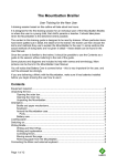
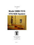
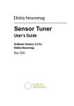
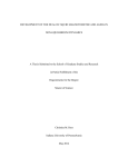
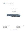
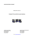
User's Manual for model 703G HTS SQUID multi-channel Gradiometer System By Tristan Technologies, Inc. San Diego, California USA copyright 1999 i Tristan Part Number 3000-120 Revision Record Date Revision Description April 1, 1999 A Initial Release July 28, 2003 B Product Update June 21, 2004 C Product Update July 9, 2004 C1 typo corrections 1998, 2004 by Tristan Technologies, Inc. All rights reserved. No part of this manual may be reproduced, stored in a retrieval system, or transmitted in any form or by any means, electronic, mechanical, photocopying, recording, or otherwise, without prior written permission of Tristan. Tristan reserves the right to change the functions, features, or specifications of its products at any time, without notice. Any questions or comments in regard to this product and other products from Tristan please contact: Customer Service Tristan Technologies, Inc. 6191 Cornerstone Court East Suite 107 San Diego, CA 92121 USA Phone: (858) 550-2700 FAX: (858) 550-2799 [email protected] http://www.tristantech.com ii TABLE OF CONTENTS 1. WARRANTY...............................................................................................................................................1 2. GENERAL INFORMATION ....................................................................................................................2 2.1 2.2 2.3 2.4 2.5 3. INSTALLATION ......................................................................................................................................12 3.1 3.2 4. INTRODUCTION ............................................................................................................................... 2 SYSTEM COMPONENTS .................................................................................................................2 MEASURED PARAMETERS AND FACTORY TEST DATA .........................................................3 SAFETY PRECAUTIONS ................................................................................................................11 USE OF LIQUID NITROGEN ..........................................................................................................12 INITIAL INSPECTION ....................................................................................................................13 NORMAL INSTALLATION ............................................................................................................13 NORMAL OPERATION .........................................................................................................................14 4.1 4.2 REFILLING THE DEWAR WITH LIQUID NITROGEN .............................................................. 14 WARM-UP PROCEDURE ...............................................................................................................14 5. TROUBLE SHOOTING .......................................................................................................................... 15 6. MAINTENANCE ......................................................................................................................................16 6.1 6.2 DEWAR VACUUM .......................................................................................................................... 16 HIGH TEMPERATURE SQUID SENSOR ADVISORY .................................................................17 TABLE OF FIGURES FIGURE 1 FIGURE 2 FIGURE 3 FIGURE 4 FIGURE 5 FIGURE 6 FIGURE 7 FIGURE 8 FIGURE 9 FIGURE 10 FIGURE 11 FIGURE 12 703G SYSTEM COMPONENTS. ..........................................................................................................2 SG40323 SENSITIVITY .....................................................................................................................3 SG40324 SENSITIVITY .....................................................................................................................4 SG40325 SENSITIVITY .....................................................................................................................4 SG40323 NOISE MEASURED AT TRISTAN .........................................................................................6 SG40324 NOISE MEASURED AT TRISTAN .........................................................................................7 SG40325 NOISE MEASURED AT TRISTAN .........................................................................................8 NLD-530 DEWAR DIMENSIONS - INCHES (MM)...............................................................................10 NLI-53G PROBE ............................................................................................................................ 11 GRADIOMETER ORIENTATION ........................................................................................................11 SHUNTING PLUGS .......................................................................................................................... 18 SILICA GEL INDICATOR COLORS ....................................................................................................18 TABLE OF TABLES TABLE 1 DEWAR TEST REPORT RESULTS ................................................................................................................9 iii 1. WARRANTY Tristan Technologies, Inc. warrants its products to be free from defects in material and workmanship. Obligations under this warranty shall be limited to replacing, repairing, or giving credit for the purchase price, at Tristan’s option, of any instrument returned, shipment prepaid, to its factory for that purpose within one year of delivery to the original purchaser, provided prior authorization for such return has been given by an authorized Tristan representative. This warranty shall not apply to any instrument which Tristan’s inspection discloses to have become defective or unworkable due to abuse, mishandling, misuse, accident, alteration, negligence, improper installation, or other causes. This warranty shall not apply to any instrument or component not manufactured by Tristan. When products manufactured by others are included in Tristan’s equipment, the original manufacturer's warranty, if any, is extended to purchaser to the extent permitted by that manufacturer. Tristan reserves the right to make changes in design at any time without incurring any obligation to install same on units previously purchased. There are no warranties which extend beyond the description herein. This warranty is in lieu of, and excludes any and all other warranties or representations, expressed, implied or statutory, including merchantability and fitness for purpose as well as any and all other obligations or liabilities of seller, including, but not limited to, special or consequential damages. No person, firm or corporation is authorized to assume for Tristan any additional obligation or liability not expressly provided for herein. Page 1 of 23 2. GENERAL INFORMATION 2.1 INTRODUCTION This instruction manual contains installation, operation and maintenance instructions for the model 703G HTS SQUID gradiometer measurement system supplied by Tristan Technologies, Inc. A schematic of the system is included for reference as Figure 1. CC-6 composite cables iFL-301-H flux-locked loops iMC-303 SQUID Control Electronics NLD-530 Dewar Figure 1 703G system components. 2.2 SYSTEM COMPONENTS Please check the enclosed packing list carefully when unpacking the equipment to verify that everything is present and undamaged. We recommend that you save the shipping crates for possible future use in case the system has been damaged and needs to be repaired. 2.2.1 List of system components Model iMC-303 iMAG® SQUID Control Electronics S/N # 1093 Model iFL-301-H iMAG® Flux Locked Loops (3) S/N # 2061 S/N # 2062 S/N # 2064 Model NLD-530 liquid nitrogen dewar S/N # 141 LN2 filling funnel Model NL-53G 3-channel SQUID probe S/N # 146 Model HTG-10R planar SQUID gradiometers (3) S/N # SG40323 (dBz/dy) S/N # SG40324 (dBx/dy) S/N # SG 40325 (dBz/dx) 1 1iMAG® is a Registered Trademark of Tristan Technologies, Inc. All Rights Reserved Page 2 of 23 Model CC-6 six meter composite cables (3) Power Cord HTS iMAG® User’s Manual and Applications Disk The country of origin for all components is the United States, with the exception of the HTG-10R SQUID sensors whose country of origin is Germany. 2.3 MEASURED PARAMETERS AND FACTORY TEST DATA The following parameters were measured at Tristan prior to shipment. Dimensions and weights are approximate and are given for reference only. Performance data is the result of testing done at Tristan. Boil-off tests values were taken after thermal equilibrium was established. Under ideal conditions, you should expect to achieve similar performance in your laboratory, but small differences are to be expected. 2.3.1 SQUID sensors SQUID sensors are initially tested in a HTS superconducting shield to eliminate external environmental noise contributions. The HTS shield is inside a multiple layer mu-metal shield to ensure that the ambient field is minimized. Testing is done using Tristan iMAG® 300 SQUID electronics. The flux transfer function (nT/cmo) and noise (fT/cmHz) are determined for each sensor. The test results of the supplied SQUID sensors are shown below as a function of frequency. The white noise (guaranteed to be < 70 fT/cmHz) was measured at 100 Hz and are listed below each respective graph along with sensitivity at 1 Hz (not a guaranteed value, but shown for informational purposes). Figure 2 SG40323 Sensitivity White Noise (measured at 100 Hz): 32 fT/cmHz; noise at 1 Hz ~72 fT/cmHz Page 3 of 23 Figure 3 SG40324 Sensitivity White Noise (measured at 100 Hz): 25 fT/cmHz; noise at 1 Hz ~60 fT/cmHz Figure 4 SG40325 Sensitivity White Noise (measured at 100 Hz): 33 fT/cmHz; noise at 1 Hz ~85 fT/cmHz 2.3.1.1 Measurements in a non-superconducting shield Additional measurements were made at Tristan in a MS-830 three layer nonsuperconducting mu-metal shield (5.5” i.d.). These tests determine the bandwidth and voltage transfer function for each device. Operation at various gains and ranges are verified using the customer’s electronics. Testing is done using Hewlett-Packard (34401A DMM, 35665A dynamic signal analyzer) and other appropriate test Page 4 of 23 equipment. Typically, multiple average FFT’s are taking using a Hanning window to give the spectra shown below. Because of the local environmental noise, these measurements (Figure 5 -Figure 7) show different noise levels than the results shown in figures 1-3 (channel 1: 22 vs. 32 fT/cmHz shielded; channel 2: 100 vs. 25 fT/cmHz shielded; channel 1: 58 vs. 33 fT/cmHz shielded). It should be noted that HTS SQUID sensors typically show a 10 - 30% variation from device to device. Channel 2’s higher noise may be due to its vertical orientation in the mu-metal shield. These tests were not to demonstrate ultimate performance in a remote environment, but to verify proper operation of the SQUID electronics; higher noise is typical of unshielded operation. Reducing external noise contributions can be very difficult. In gradiometers—especially in a laboratory environment—significant noise can be introduced if the dewar is positioned near a metal fixture. Section 5 discusses ways to reduce the influence of environmental noise sources. Page 5 of 23 Figure 5 SG40323 noise measured at Tristan Test configuration SQUID Controller used Flux-locked Loop used SQUID sensor used System Channel # Test Setup Gain: x100 iMC-303 iFL-301-H Slew: S/N: 1093 S/N: 2061 S/N: SG40323 1 Normal Heater Test Heat Time: 9 sec Autotune Cool Time:> 99 sec Triangle Amplitude: 2 Vpeak-to-peak Tune Parameters Bias + Bias Mod Skew Gain Slew 18% 18% 18% 23% X100 Normal X100 Slow X50 Normal units 0.52 N/A N/A V/o Noise @ 1 kHz 22 N/A N/A fT/cmHz Bandwidth 3 N/A N/A kHz yes yes yes N/A Loop Locked Page 6 of 23 Figure 6 SG40324 noise measured at Tristan Test configuration SQUID Controller used Flux-locked Loop used SQUID sensor used System Channel # Test Setup Gain: x100 iMC-303 iFL-301-H Slew: S/N: 1093 S/N: 2062 S/N: SG40324 2 Normal Heater Test Heat Time: 15 sec Cool Time:> 99 sec Autotune Triangle Amplitude: 0.8 Vpeak-to-peak Tune Parameters Bias + Bias Mod Skew Gain Slew 53% 53% 10% 2% X100 Normal X100 Slow X50 Normal units 0.51 N/A N/A V/o Noise @ 1 kHz 100 N/A N/A fT/cmHz Bandwidth 3.5 N/A N/A kHz Loop Locked yes yes yes N/A Page 7 of 23 Figure 7 SG40325 noise measured at Tristan Test configuration SQUID Controller used Flux-locked Loop used SQUID sensor used System Channel # Test Setup Gain: x100 iMC-303 iFL-301-H Slew: S/N: 1093 S/N: 2064 S/N: SG40325 3 Normal Heater Test Heat Time: 15 sec Cool Time:> 99 sec Autotune Triangle Amplitude: 1.4 Vpeak-to-peak Tune Parameters Bias + Bias Mod Skew Gain Slew 40% 40% 72% 4% X100 Normal X100 Slow X50 Normal units 0.51 N/A N/A V/o Noise @ 1 kHz 58 N/A N/A fT/cmHz Bandwidth 6 N/A N/A kHz yes yes yes N/A Loop Locked Page 8 of 23 2.3.1.2 Unshielded Operation For planar gradiometers, testing is also done in an unshielded environment. Completely unshielded operation was achieved with all three channels simultaneously. Channel 1 Channel 1 Channel 1 yes yes yes Loop Locked 2.3.2 Dewar Parameters The dewar construction (Figure 8) is that of a vacuum insulated vessel with the outer case constructed of G-10 fiberglass, superinsulation in the vacuum space to reduce blackbody radiation and inner vessel (also G-10 construction) that acts as the nitrogen reservoir. Volume 1.19 Liters Boil off (no probe) 0.30 L/Day Hold Time (no probe) Boil off (with probe) ~4 Days 0.36 L/Day Hold Time (no probe) ~3 Days Weight Empty 1.42 kg. Weight Full (no probe) 2.23 kg. Dewar Tail (approximate) 0.12 inches Gap 3 mm Table 1 Dewar Test Report Results Page 9 of 23 Figure 8 NLD-530 dewar dimensions - inches (mm) 2.3.3 Probe configuration Knowledge of the total magnetic field gradient determination of its magnitude and direction2. Bx x B y x Bz x Bx y B y y Bz y Bx Bx z x B y B y z x Bz z B) of an object can allow Bx z By z Bz z From Maxwell’s Equations, four of the gradients are redundant Thus only five gradient components are necessary to determine H as shown above. The model 703G 3-channel SQUID gradiometer was designed to measure the three unique planar gradients (n. b., dBz/dy = -dBy/dz, dBx/dy = -dBy/dx, and dBz/dx = -dBx/dz), The insert probe is shown in Figure 9. The three LEMO connectors on the top of the insert are labeled to indicate which connector corresponds to which sensor. 2 Wynn, W., Frahm, C., Carroll, P., Clark, R. Welhoner, J. and Wynn, M., “Advanced Superconducting Gradiometer/Magnetometer Arrays and a Novel Signal Processing Technique”, IEEE Transactions on Magnetics, 11, pp. 701-707. (1975) Page 10 of 23 Figure 9 NLI-53G Probe Figure 10 shows the layout of the three HTS planar gradiometer SQUID sensors. dBz/dy Z dBx/dy Y X dBz/dx Figure 10 Gradiometer Orientation 2.3.4 Electronics and software See the User's Manual for iMAG HTS® Multi-Channel dc SQUID System for information on the use of the electronics and software. 2.4 SAFETY PRECAUTIONS 2.4.1 SAFETY PRECAUTIONS FOR HANDLING LIQUID NITROGEN The potential hazards of handling liquid nitrogen stem mainly from the following properties: 1. The liquid is extremely cold. 2. The ultra-low temperature of liquid nitrogen can condense and solidify air. 3. Very small amounts of liquid nitrogen are converted into large volumes of gas. 4. Nitrogen is not life supporting. 2.4.2 EXTREME COLD-- COVER EYES AND EXPOSED SKIN Page 11 of 23 Accidental contact of liquid nitrogen or the cold gas that results from its rapid evaporation may cause a freezing injury similar to a burn. Protect your eyes and cover the skin where the possibility of contact exists. Eye protection should always be worn when transferring liquid nitrogen. 2.4.3 KEEP EXTERIOR SURFACES CLEAN TO PREVENT COMBUSTION Atmospheric air will condense on exposed nitrogen-cooled piping. Nitrogen, having a lower boiling point than oxygen, will evaporate first from condensed air, leaving an oxygen-enriched liquid that may drip or flow to nearby surfaces. Areas and surfaces upon which oxygen-enriched liquid can form, or come in contact with, must be cleaned to oxygen-clean standards to prevent possible ignition of grease, oil, or other combustible substances. Leak-testing solutions should be selected carefully to avoid mixtures which can leave a residue that is combustible. When combustible type foam insulations are used, they should be carefully applied to reduce the possibility of exposure to oxygen-enriched liquid which could, upon impact, cause explosive burning of the foam. CAUTION: DO NOT MAKE ANY MODIFICATIONS TO THIS SYSTEM WHICH MIGHT AFFECT ITS ABILITY TO VENT NITROGEN GAS IN THE EVENT OF AN EMERGENCY SUCH AS LOSS OF VACUUM IN THE DEWAR VACUUM SPACE. 2.4.4 KEEP EQUIPMENT AREA WELL VENTILATED Although nitrogen is nontoxic, it can cause asphyxiation in a confined area without adequate ventilation. Any atmosphere which does not contain enough oxygen for breathing can cause dizziness, unconsciousness, or even death. Nitrogen, being colorless, odorless, and tasteless cannot be detected by the human senses and will be inhaled normally as if it were air. Without adequate ventilation, the expanding nitrogen can displace air and result in an atmosphere that is not life-supporting. The cloudy vapor that appears when liquid nitrogen is exposed to the air is condensed moisture, not the gas itself. The issuing nitrogen gas is invisible. Liquid containers should be stored in large, well ventilated areas. If a person becomes groggy or loses consciousness when working around nitrogen, get them to a well ventilated area immediately. If breathing has stopped, apply artificial respiration. If a person loses consciousness, summon a physician immediately. 2.5 USE OF LIQUID NITROGEN This system is designed for use ONLY with liquid nitrogen. Instructions for precooling the probe and dewar are given in Section 3.2.1 of this manual. 3. INSTALLATION Page 12 of 23 3.1 INITIAL INSPECTION All Tristan instruments and equipment are carefully inspected and packaged at Tristan prior to shipment. However, if a unit is received mechanically damaged, notify the carrier and the nearest Tristan representative, or the factory in San Diego, California. Keep the shipping container and packing material for the carrier and insurance inspections. If the unit does not appear to be damaged but does not operate to specifications, contact the nearest Tristan representative or the Tristan factory and describe the problem in detail. Please be prepared to discuss all surrounding circumstances, including installation and connection detail. After obtaining authorization from the Tristan representative, return the unit for repair along with a tag to it identifying yourself as the owner. Please enclose a letter describing the problem in as much detail as possible. 3.1.1 REPACKING FOR RETURN SHIPMENT If it is necessary to return the system, you should repack the unit in its original container (if available). For this reason, it is advisable to save the original crate sent by Tristan; however, if this is not possible, use the following instructions for repacking. 1. Wrap the unit in either bubblewrap or foam rubber. 2. Cover the bottom of a sturdy container with at least 3 inches of Styrofoam pellets or shredded paper. 3. Set the unit down onto the packing material and fill the rest of the container with Styrofoam or shredded paper. The unit must be completely protected by at least 3 inches of packing material on all sides. 3.1.2 RETURN FROM CUSTOMERS OUTSIDE THE USA To avoid delays in Customs clearance of equipment being returned, contact the Tristan representative in your area, or the Tristan factory in San Diego, California, for complete shipping information and necessary customs requirements. Failure to do so can result in significant delays. 3.2 NORMAL INSTALLATION 3.2.1 COOLING THE SYSTEM FROM ROOM TEMPERATURE Install the funnel in the neck of the dewar. Fill the dewar by slowly adding LN 2 until half full. This could take a few minutes. Remove the funnel and slowly lower the probe into the dewar. If liquid nitrogen bubbles or spurts out of the dewar, you are lowering the probe too fast. Avoid freezing the o-ring and pump-out fitting. When fully lowered, secure the probe to the dewar with the proper hardware. Remove the fill tube plug and install the funnel into the fill tube. Again, slowly pour LN2 into the funnel until LN2 vents from the vent port. Wait a moment and then add more LN2 until it again vents from the vent port. Repeat this sequence until adding Page 13 of 23 LN2 causes immediate venting. The dewar is now filled. Remove the funnel and replace it with the fill tube plug. CAUTION: O-rings located on the probe will not be flexible if cold and may easily be cracked. Spare o-rings are provided. CAUTION: To avoid contamination of the vacuum space, do not freeze the pump-out valve on the top of the probe or the gasket on the top of the probe during transfer. 4. NORMAL OPERATION 4.1 REFILLING THE DEWAR WITH LIQUID NITROGEN After the initial nitrogen transfer, subsequent transfers will be required on a regular basis. The boil-off time recorded in Table 1 for the dewar will be reduced when a probe is installed and operating. The dewar is designed to operate in the vertical position. Boil-off will increase when the dewar is tilted from vertical. The boil-off of the dewar with probe should be measured—this will determine the minimum time between refills of the dewar. The dewar should be refilled periodically and should not be allowed to warm unintentionally via boil-off. To refill a cold dewar, remove the fill tube plug and install the provided funnel into the fill tube. Slowly pour LN2 into the funnel until LN2 vents from the vent port. Wait a moment and then add more LN2 until it again vents from the vent port. Repeat this sequence until adding liquid causes immediate venting. The dewar is now filled. Remove the funnel and replace it with the fill tube plug. 4.2 WARM-UP PROCEDURE If the SQUID magnetometer probe is not in the dewar, then pouring out the liquid nitrogen or, letting the liquid nitrogen evaporate is acceptable, However, since HTS SQUID sensors will be damaged by exposure to moisture (section 6.2), special precautions must be taken when warming up dewars that are being used to cool HTS SQUIDs. To prevent exposure to moisture, immediately remove the probe and place the probe inside a tight-fitting plastic bag to prevent excessive condensation of moisture. Be sure that a desiccant is inside the bag. When the probe and sensors have warmed up to room temperature, place the probe in a moisture-free container (e.g., a dry box). After removing the probe, turn the dewar upside down to pour out the remaining nitrogen. Be sure not to pour the liquid nitrogen on anything that could be damaged. Then let the dewar warm up to room temperature (leave the neck tube open). Turning the dewar upside down will minimize the amount of moisture that may condense inside the dewar. If this procedure is used, it will be necessary to make sure that any water which condenses in the dewar is removed prior to using the Page 14 of 23 system again. This can be done by wiping it out using a rag on the end of a rod or by blowing room-temperature air into the tail of the dewar. WARNING: DO NOT BLOW HOT AIR INTO THE DEWAR AS THIS MAY CAUSE FAILURE OF THE EPOXIED JOINTS. 5. TROUBLE SHOOTING The greatest obstacle to SQUID measurements is external noise sources. Metallic shielding can minimize external noise (e.g., act as a low pass eddy current shield). In the case of HTS SQUID sensors, the use of high permeability mu-metal shields (such as the Tristan MS-830) can significantly attenuate external field variations. This assumes that any electrical inputs to the experimental region have been appropriately filtered. Powerline or microprocessor clock frequencies can severely degrade performance. Unfortunately, if external objects are to be measured, external shields are not appropriate. However, external shields are helpful in verifying proper operation of the SQUID system and electronics. When measuring external fields, the SQUID magnetometer must operate in an environment — the magnetic field of the earth — that can be 10 orders of magnitude greater than its sensitivity. The magnetic field at the surface of the earth is generated by a number of sources. There exists a background field of ~50 µT with a daily variation of ± 0.1 µT. In addition, there is a contribution (below 1 Hz) from the interaction of the solar wind with the magnetosphere. The remaining contributions to external magnetic fields are primarily man-made. These can be caused by structural steel and other localized magnetic materials such as furniture and instruments that distort the earth’s field and result in field gradients, moving vehicles that generate transient fields, electric motors, elevators, radio, television, and microwave transmitters, and the ever present powerline electromagnetic field and its harmonics. It is highly advisable to perform initial tests in a magnetically shielded environment. If you do not have a shielded room, measurements made after midnight or on the weekend can be compared to measurements during the day to see if there are environmental effects. If rfi is of concern, wrapping the dewar in aluminum foil may improve the situation. This acts as an eddy current shield. While it may reduce the system’s bandwidth (depending on the amount of aluminum foil used) and perhaps increase the system’s white noise, it can be very effective in attenuating rfi. As mentioned above, significant gradient noise can be introduced if the dewar is positioned near a metal fixture (such as a steel filing cabinet) or a power distribution box. If a planar gradiometer is being tested, rotating the gradiometer (anywhere from 30º~90º) can often make a significant change in the measured gradient noise. During the initial testing, be sure that the system is on a sturdy platform. A flimsy table may cause motion induced noise. Also be sure that the platform (or whatever mounting is being used) is free of any ferromagnetic contaminants. Avoid using conductive metal tables as they can couple in gradient noise. Page 15 of 23 6. MAINTENANCE 6.1 DEWAR VACUUM Prior to cooling down (especially if the dewar has been at room temperature for a long period of time), the dewar vacuum should be checked to verify that the vacuum space is evacuated. Eventually, the vacuum space of the dewar will need to be re-evacuated. This will become obvious in one of two ways: The nitrogen evaporation rate will increase during normal operation. If the evaporation rate has increased by more than 30%, you should consider repumping the vacuum space. You will be unable to transfer liquid nitrogen. All of the nitrogen transferred into the dewar will immediately evaporate. If the vacuum is extremely poor, the outside of the dewar may get cold and even condense water, especially along the tail. If you suspect a poor vacuum, use the following procedure to check and pump on the vacuum: WARNING: EXTREME caution must be used when examining the vacuum. There are many fine layers of superinsulation in the vacuum space. Rapid changes in pressure may cause rupturing of the superinsulation. Therefore, NEVER abruptly open the dewar vacuum space to atmospheric pressure; the dewar vacuum should be slowly vented over a period of about 15 minutes. The nitrogen reservoir must always be at room temperature when gas is admitted to the vacuum space or when it is being pumped. The dewar is equipped with a vacuum space evacuation valve mounted on the dewar top. Before opening this valve, a leak-tight connection should be made to it and the pumping line to the valve should be evacuated using a leak detector or a pumping station equipped with a diffusion pump and cold trap (or other pumping system with equivalent capability). The cold trap is necessary to prevent backstreaming of pump oil into the vacuum space after it has reached a low, static pressure. WARNING: OPEN THE VALVE VERY SLOWLY AND OBSERVE THE PRESSURE IN THE DEWAR. DO NOT BEGIN PUMPING UNTIL YOU OBSERVE THE PRESSURE. If you observe a high pressure (more than a few torr), you should pump the vacuum space very slowly by opening the valve as little as possible. Page 16 of 23 A satisfactory vacuum is about 100-200 millitorr when the whole dewar is at room temperature. Depending on the pressure, it may take up to 24 hours to obtain a satisfactory pressure. WARNING: DO NOT LEAVE THE DEWAR PUMPING UNATTENDED. Since most of the time required is for outgassing of the surfaces in the dewar, it is better to pump the dewar for 15 minutes every few hours. There is little advantage to leave the pump connected continuously. If you suspect that there is water or other contaminants in the vacuum space, it may be advantageous to flush the vacuum space with nitrogen gas. Slowly fill the vacuum space with 10 torr of nitrogen gas (this should not be done at a rate faster than 1 torr per minute). It should then be re-evacuated as described above. This procedure may be repeated several times. WARNING: THE PRESSURE IN THE VACUUM SPACE MUST NEVER BE ALLOWED TO CHANGE QUICKLY. RAPID PRESSURE CHANGES WILL CAUSE PERMANENT DAMAGE TO THE THERMAL SHIELD AND SUPERINSULATION. If the dewar does not perform well after pumping the vacuum, or if it requires pumping at intervals more frequent than once a year, there may be a leak in the dewar. If you suspect this problem, contact your Tristan representative for assistance. 6.2 HIGH TEMPERATURE SQUID SENSOR ADVISORY In order to insure optimum performance for your Tristan High Temperature SQUID system, the following handling precautions should be followed. Carefully adhering to these procedures will allow your instrument to function accurately for the duration of the warranty period and beyond. Please feel free to contact Tristan with any questions. 6.2.1 Handling for Shipping and/or Storing at Room Temperature SQUIDs are electro-static discharge (ESD) sensitive devices. Always store them in appropriate ESD safe packaging. Use appropriate static sensitive handling equipment such as ESD mats and wrist straps when handling and connecting High Temperature SQUIDs. Connect the shunting plug at the top connector when the SQUID is not in use for extended periods and always for shipment. See Figure 11. Page 17 of 23 Shunting plug side view Shunting plug end view SQUID with shunting plug installed Figure 11 SQUID without shunting plug installed Shunting Plugs Be sure to install shunting plugs on the connector of the SQUID when it is not in use for extended periods or during shipping. Store the SQUID sensor in a moisture free environment by using desiccant in conjunction with a closed container. This is especially important in humid or damp environments. Typically desiccant (Silica Gel) appears blue when active and red or pink when saturated with moisture. See Figure 12. Figure 12 Silica Gel Indicator Colors A Blue color indicates that the desiccant is still active. A Red color indicates that the desiccant should be replaced. When warming the SQUID sensor, immediately place the SQUID sensor in a plastic bag when it is removed from the cryogen to minimize the condensation of water vapor on the cold surfaces. After the SQUID sensor Page 18 of 23 reaches room temperature, dry the body of the SQUID sensor / Probe (observing ESD precautions) and then store with desiccant. When testing the SQUID cables at room temperature limit the current by using a manual range on a low current digital multi-meter. Do not use the auto-range function of the digital multi-meter. Select the “K range”. Do not heat the SQUID (using HEAT button on the Tristan model iMC-303 SQUID Control Electronics or equivalent heating circuit) at when the SQUID sensor is at room temperature. Ship the SQUID sensor with the shunting plug attached and in a closed container with desiccant inside. NEVER allow the SQUID to sit in a sealed dewar with water condensed on the bottom. WARNING: MOISTURE DAMAGE DUE TO FAILURE TO FOLLOW THESE INSTRUCTIONS WILL VOID THE WARRANTY. 6.2.2 HTS Sensor Cool Down and Usage Do not touch the pins or connector of the SQUID. Observe ESD precautions when connecting the SQUID’s cables. Do not measure SQUID cable resistances when cold. Initial cool down of the SQUID is with the Tristan iFL-301-H flux-locked loop electronics connected to the LEMO connectors at the top of the cryostat. However, do not yet connect the CC-6 composite cable(s) to the iFL-303-H Flux Lock Loop(s). Connect the CC-6 composite cable(s) to the Tristan model iMC-303 SQUID Control Electronics first. Turn on the Tristan electronics with the SQUID not connected. Go to SETUP; MANUAL TUNING; ENTER and then reduce Bias, Mod, and Skew to 0%. Allow the SQUID electronics to stabilize for 10 minutes. Connect the CC-6 composite cable(s) at the Flux Lock Loop first, then connect 10-pin LEMO connector, and then connect the 5-pin LEMO connector last. If the SQUID is in a vacuum, verify that the correct heater current limits are in place. This is not normally applicable to the 703G system, but is relevant if you are performing other tests. Run the TUNE Utility. Heat for about 3 seconds, then pause for 2 minutes. If the SQUID does not go “normal” (as seen by observing the triangles—as described in the User's Page 19 of 23 Manual for iMAG HTS® Multi-Channel dc SQUID System), you may increase the heat time (in small increments) until the SQUID goes normal. If the heat time becomes excessively long, contact Tristan or your local distributor for advice before proceeding. Run the TUNE Utility. When turning off the system, set Bias and Mod and Skew to 0%, disconnect the CC-6 composite cable(s) and then turn off AC power. When disconnecting all cables, disconnect the 5-pin LEMO connector first, then the 10-pin LEMO connector. Page 20 of 23