1
CD1-k
User Guide
gb
CANopen
Amplifier
INFRANOR®
CD1-k
1
CD1-k – User Guide
WARNING
!
This is a general manual describing a series of servo amplifiers having output capability suitable for driving AC
brushless sinusoidal servo motors. This manual may be used in conjunction with appropriate and referenced
drawings pertaining to the various specific models.
Please see CD1-k Installation Guide for the hardware installation of the amplifier (dimensions, wiring, ...).
For the CANopen communication, see manual CD1-k – CANopen Communication Profile.
Instructions for storage, use after storage, commissioning as well as all technical details require the
MANDATORY reading of the manual before getting the amplifiers operational.
Maintenance procedures should be attempted only by highly skilled technicians having good knowledge
of electronics and servo systems with variable speed (EN 60204-1 standard) and using proper test
equipment.
The compliance with the standards and the "CE" approval is only valid if the items are installed according to the
recommendations of the amplifier manuals. Connections are the user's responsibility if recommendations and
drawings requirements are not met.
Any contact with electrical parts, even after power down, may involve severe physical damage.
Wait for at least 5 minutes after power down before handling the amplifiers (a residual voltage of several
hundreds of volts may remain during a few minutes).
ESD INFORMATION (ElectroStatic Discharge)
INFRANOR amplifiers are conceived to be best protected against electrostatic discharges. However,
some components are particularly sensitive and may be damaged if the amplifiers are not properly
stored and handled.
STORAGE
-
The amplifiers must be stored in their original package.
When taken out of their package, they must be stored positioned on one of their flat metal
surfaces and on a dissipating or electrostatically neutral support.
Avoid any contact between the amplifier connectors and material with electrostatic potential
(plastic film, polyester, carpet…).
HANDLING
-
If no protection equipment is available (dissipating shoes or bracelets), the amplifiers must
be handled via their metal housing.
Never get in contact with the connectors.
ELIMINATION
In order to comply with the 2002/96/EC directive of the European Parliament and of the Council of
27 January 2003 on waste electrical and electronic equipment (WEEE), all INFRANOR devices
have got a sticker symbolizing a crossed-out wheel dustbin as shown in Appendix IV of
the 2002/96/EC Directive.
This symbol indicates that INFRANOR devices must be eliminated by selective disposal and not
with standard waste.
INFRANOR does not assume any responsibility for physical or material damage due to improper handling or
wrong descriptions of the ordered items.
Any intervention on the items, which is not specified in the manual, will immediately cancel the warranty.
Infranor reserves the right to change any information contained in this manual without notice.
©INFRANOR, September 2005. All rights reserved
Issue: 2.0
2
CD1-k
CD1-k – User Guide
Content
PAGE
CONTENT ............................................................................................................................................... 3
CHAPTER 1 - GENERAL DESCRIPTION ............................................................................................. 4
1 - INTRODUCTION............................................................................................................................. 4
2 - ARCHITECTURE OF THE AMPLIFIER .......................................................................................... 4
CHAPTER 2 - COMMISSIONING........................................................................................................... 6
1 - INSTALLATION OF THE PARAMETER SETTING SOFTWARE.................................................... 6
2 - CHECKING THE AMPLIFIER HARDWARE CONFIGURATION .................................................... 6
3 - POWERING OF THE AMPLIFIER................................................................................................... 6
4 - STARTING AND ADJUSTING THE AMPLIFIER ............................................................................ 7
4.1 - AMPLIFIER ADJUSTMENT TO THE MOTOR SPECIFICATIONS ......................................... 7
4.2 - I2t PROTECTION.................................................................................................................... 10
4.3 - SERVO LOOP ADJUSTMENT............................................................................................... 11
4.4 - ROTATION / COUNTING DIRECTION.................................................................................. 12
5 - PARAMETER SAVING.................................................................................................................. 12
6 - MOTOR PHASING (PHASING) AT POWER ON ............................................................................. 12
7 - INCREMENTAL ENCODER OUTPUTS ....................................................................................... 13
8 - COGGING TORQUE COMPENSATION ...................................................................................... 13
CHAPTER 3 - FUNCTIONAL FEATURES........................................................................................... 15
1 - LOGIC INPUTS ............................................................................................................................. 15
1.1 - "INHIBIT" INPUT..................................................................................................................... 15
1.2 - "LIMIT SWITCH" INPUTS ...................................................................................................... 15
1.3 - "LOW SPEED" INPUT ............................................................................................................ 15
1.4 - "INDEX" INPUT ...................................................................................................................... 15
2 - BRAKE CONTROL........................................................................................................................ 15
3 - ADDRESSING SWITCH / SPEED SELECTION ........................................................................... 16
CHAPTER 4 - CANOPEN COMMUNICATION .................................................................................... 17
CHAPTER 5 - TROUBLESHOOTING & MAINTENANCE .................................................................. 18
1 - ERRORS .......................................................................................................................................... 18
1.1 - "SYSTEM" ERROR ................................................................................................................ 18
1.2 - NON STORED ERRORS ....................................................................................................... 18
1.3 - STORED ERRORS ................................................................................................................ 18
2 - ERROR RESET............................................................................................................................. 23
3 - OPERATION PROBLEMS ............................................................................................................ 23
3.1 - MOTOR DOES NOT MOVE................................................................................................... 23
3.2 - MOTOR ENABLED BUT LITTLE TORQUE........................................................................... 23
3.3 - SHAFT LOCKED – ERRATIC OSCILLATIONS - rotation AT MAXIMUM SPEED ................ 23
3.4 - DISCONTINUOUS MOTOR ROTATIONS WITH ZERO TORQUE POSITIONS .................. 23
3.5 - LOUD CRACKLING NOISE IN THE MOTOR AT STANDSTILL ........................................... 23
4 - SERVICE AND MAINTENANCE ................................................................................................... 23
CD1-k
3
CD1-k – User Guide
Chapter 1 - General description
1 - INTRODUCTION
CD1-k all-digital amplifiers with sinusoidal PWM control are servo amplifiers that provide the control of brushless
AC motors with position sensor.
The CD1-k amplifier is a stand-alone single-axis block including power supply unit and mains filters. It is available
in both 230 VAC and 400/480 VAC mains operated voltages.
CD1-k amplifiers are working via a bus with "CANopen" communication protocol.
The amplifier parameter setting can be made either by means of:
•
the CANopen bus or
•
the specific parameter setting software Visual Drive Setup, via the serial port RS-232.
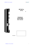
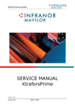
2 - ARCHITECTURE OF THE AMPLIFIER
CANopen
interface
Position
regulator
Speed
regulator
Position
measurement
Speed
measurement
Current
regulator
Motor
Current
measurements
Resolver
4
Chapter 1 - General description
CD1-k – User guide
Electric motor
Electric device that transforms electrical energy into a mechanical movement.
This transformation is often made by means of current commutation.
Generally, the movement is a rotation but there are also linear motors.
Brushless or synchronous
motor
Electric brushless motor. The current commutation is electronically made and
requires a position sensor (resolver, encoder, Hall sensor...).
Resolver
Absolute position sensor over one revolution. The resolver is often used
together with brushless motors because of its robustness.
Encoder
Incremental or absolute position sensor. The encoder is used together with
brushless motors for its accuracy.
Amplifier
Electric device for the control of electric motors. It also includes a current
regulator, a speed regulator and, often, a position regulator.
Current loop
Current regulator
Used for the motor current control. The motor torque is generally proportional
to the current amplitude.
Speed loop
Speed regulator
Allows the motor speed control.
Position loop
Position regulator
Allows the motor position control.
Fieldbus
Digital link that allows real time data exchange between various electric
devices. The characteristic of fieldbusses is their high protection and error
correction level as well as a predictable communication time.
CANopen
Communication protocol on CANbus – Standards: CiA DS301 / CiA DSP402.
Enabled/disabled
(Servo On/Off)
When a motor is enabled, it is controlled by the amplifier and the servo loops
are operating. When it is disabled, its rotation is free and there is no current
in the motor.
Chapter 1 – General description
5
CD1-k – User Guide
Chapter 2 - Commissioning
CAUTION !
Do not make the amplifier parameter setting by means of both Visual Amplifier Setup software and
CANopen bus at the same time.
1 - INSTALLATION OF THE PARAMETER SETTING SOFTWARE
The Visual Drive Setup software is PC compliant under Windows® 1 and allows an easy parameter setting of the
CD1-k amplifier.
Please see our website www.infranor.fr for downloading the "Visual Amplifier Setup" software.
2 - CHECKING THE AMPLIFIER HARDWARE CONFIGURATION
The standard amplifier configuration is adjusted to MAVILOR motors (resolver sensor with transformation ratio =
0.5);
For the adjustment to other motor types, please see "CD1-k - Installation Guide".
3 - POWERING OF THE AMPLIFIER
Please see manual "CD1-k - Installation Guide" before switching on the amplifier for the first time.
For switching on the amplifier, please proceed as follows:
•
Switch on the +24V auxiliary supply:
The green front panel LED "OK" must blink quickly ("Undervolt." error displayed).
The AOK relay contact (pins 9 and 10 of X2) is closed. It is then possible to control the power ON relay.
•
Switch on the power supply:
The green LED "OK" must be continuously lit: the amplifier is ready to be enabled.
CAUTION !
The 24 V auxiliary supply must always be switched on before the power supply.
It is mandatory to wait for at least 30 seconds between switching off and on again the amplifier.
1
6
Windows® is a registered trade mark of MICROSOFT® CORPORATION
Chapter 2 - Commissioning
CD1-k – User Guide
4 - STARTING AND ADJUSTING THE AMPLIFIER
This chapter describes the commissioning procedure of the amplifier by means of the " Visual Amplifier Setup"
software.
•
•
Connect the serial link RS232 between PC and amplifier.
Switch on the amplifier and start the Visual Drive Setup software on the PC, under WINDOWS®.
If the message No serial communication found is displayed on the screen, click on OK and check the following
points:
o
o
o
The amplifier must be on,
The correct RS232 connection between amplifier and PC,
The correct software configuration (Com.port, ...).
For a parameter setting of the amplifier via the Visual Drive Setup software:
•
•
Switch the amplifier to Local mode, that means switch address = 0 (see Chapter 3, section 3),
or
Disable the CANopen communication by means of Visual Drive Setup.
4.1 - AMPLIFIER ADJUSTMENT TO THE MOTOR SPECIFICATIONS
4.1.1 - CONFIGURATION OF THE SENSOR TYPE
The configuration of the sensor type is software selectable and saved in the amplifier EEPROM.
The amplifier is configured as standard for a resolver sensor. For motors equipped with a position encoder, please
proceed as follows:
♦ Select the appropriate encoder type in the Feedback configuration menu.
♦ Then select Encoder feedback and confirm this selection.
If the motor is equipped with Hall effect sensors, check that the INHIBIT input is enabled and the amplifier is on,
before moving manually the motor over one revolution or one pole pitch on linear motors. If the HES error is
displayed, switch off the amplifier and check the following points before switching it on again:
♦
♦
♦
The Hall effect sensors (HES) must be correctly connected on the amplifier X3 connector (if 60° Hall sensor
types are used, check the various wiring combination of the HES signals for finding the right wiring order).
Check for the correct supply voltage of the Hall sensors.
Check for the correct value of the Motor encoder resolution parameter.
If the motor Hall sensors do not work correctly, select the appropriate incremental encoder type (Incremental
Encoder) (without HES) in the Feedback configuration menu and start the amplifier commissioning with this
configuration.
If the motor used is equipped with an absolute Sin/Cos encoder over one revolution (Heidenhain ERN 1085 or
compliant), check that the INHIBIT input is enabled and the amplifier on. Then move manually the motor over one
revolution. If the HES error is displayed, switch off the amplifier and check the following points before switching it
on again:
♦
♦
♦
The commutation channels of the Sin/Cos encoder must be correctly wired on the amplifier X3 connector.
Check for the correct supply voltage of the Sin/Cos encoder.
Check for the correct value of the Motor encoder resolution parameter.
Perform the Save parameters to EEPROM procedure before switching off the amplifier in order to save the
sensor configuration.
Chapter 2 – Commissioning
7
CD1-k – User Guide
4.1.2 - SELECTION OF THE MOTOR TYPE
THE MOTOR USED IN THE APPLICATION IS CONTAINED IN THE MOTOR LIST OF THE PARAMETER
SETTING SOFTWARE
Select, in the motor list, the motor used in the application.
The motor selection will start the automatic calculation of the current loop parameters.
Check that the values of the parameters Max. current and Rated current are compliant with motor and amplifier.
If necessary, modify them according to the motor and amplifier specifications.
The parameter Max current defines the maximum output current value of the amplifier. It may vary between 20 %
and 100 % of the amplifier current rating.
The parameter Rated current defines the limitation threshold of the amplifier output RMS current (I2t).
It can vary between 20 % and 50 % of the amplifier current rating.
If the Incremental encoder without HES sensor configuration is selected, start a motor phasing (Phasing)
procedure.
The motor phasing can be launched either in the control window of the VISUAL DRIVE SETUP software or via the
CANopen bus.
THE MOTOR USED IN THE APPLICATION IS NOT CONTAINED IN THE MOTOR LIST OF THE PARAMETER
SETTING SOFTWARE
Select the New Motor function and follow the instructions.
4.1.3 - ENCODER COUNTING PROTECTION
When servo motors are equipped with an encoder, any error in the encoder pulse counting generates an error in
the position measurement of the rotor and may involve uncontrolled motor movements that can be dangerous for
both operator and machine. The encoder counting protection of the CD1-k amplifier range allows the detection of
pulse counting errors and immediately disables the amplifier for reasons of security.
The encoder counting protection checks that the number of encoder pulses between to successive Z marker
pulses (or R reference signals) is equal to the value of the Motor encoder resolution parameter multiplied by the
one of the Zero mark pitch parameter. The encoder counting protection also checks that the encoder pulse
frequency is lower than 1,5 times the maximum encoder frequency. The maximum encoder frequency is
calculated in the amplifier according to the value of the Motor encoder resolution and Maximum speed
parameters.
The value of the Motor encoder resolution parameter defines the number of encoder pulses (or encoder signal
periods) per motor revolution (for a rotary motor) or per motor pole pairs (for a linear motor).
The value of the Zero mark pitch parameter defines the number of motor revolutions (for a rotary motor) or of
motor pole pairs (for a linear motor) between two successive Z marker pulses (or R reference signals).
With a rotary motor, the Zero mark pitch parameter is generally equal to 1 because the encoder has got one Z
marker pulse (or one R reference signal) per motor revolution.
On a linear motor with only one marker pulse over the whole motor travel, the Zero mark pitch parameter must
be defined at 15. In this case, the encoder counting protection checks that the measured encoder position has still
got the same value when the marker pulse is activated (no drift in the position measurement).
Note: In the Incremental encoder without HES configuration, the motor phasing procedure (Phasing) must be
renewed after the release of a Counting error because the current rotor position reference for the motor
commutation is not correct.
8
Chapter 2 - Commissioning
CD1-k – User Guide
4.1.4 - PARAMETER ADJUSTMENT FOR A LINEAR MOTOR
The Motor encoder resolution parameter is calculated as follows:
N
S
N
S
N
S
Motor magnets
Pole pitch
Motor encoder resolution = 1000 x
!
Motor pole pitch (mm)
Encoder signal pitch
1 encoder signal pitch = 4 counting increments
The value of the motor Maximum speed parameter in rpm is calculated as follows:
Max. speed (rpm) = 60 x
1000
Motor pole pitch (mm)
x max. motor speed (m/s)
The linear speed value in m/s is calculated as follows:
Linear speed (m/s) =
Motor speed (rpm)
60
x
Motor pole pitch (mm)
1000
4.1.5 - MAXIMUM APPLICATION SPEED
The parameter Max. speed defines the maximum speed at which the amplifier can control the motor.
This parameter can be:
•
lower than or equal to the maximum motor speed,
•
slightly higher than the maximum motor speed in the application. This margin allows a speed overshoot
that avoids the position loop saturation (position following). This margin can be as small as possible
when using a high bandwidth or at low acceleration.
4.1.6 - CONFIGURATION OF THE THERMAL SENSOR
4.1.6.1 - Selection of the sensor type
The motor can be equipped either with a CTN sensor (ohmic resistance = decreasing temperature function) or
with a CTP sensor (ohmic resistance = increasing temperature function).
Check that the selected thermal sensor type actually corresponds to the sensor type mounted on the application
motor.
4.1.6.2 - Triggering threshold adjustment
Enter the sensor ohmic value (kOhm) corresponding to the required temperature value for the release of the
Motor overtemperature protection, according to the manufacturer's specifications.
4.1.6.3 - Warning threshold adjustment
Enter the sensor ohmic value (kOhm) corresponding to a warning temperature value.
When the warning temperature is reached, an information is sent via the CANopen bus.
Note
When using a CTN sensor, the warning ohmic value will be higher than or equal to the triggering ohmic value.
When using a CTP sensor, the warning ohmic value will be lower than or equal to the triggering ohmic value.
Chapter 2 – Commissioning
9
CD1-k – User Guide
4.2 - I2T PROTECTION
2 selection modes are available: Fusing or Limiting.
It is advisable to use the Fusing mode during commissioning phases.
In Fusing mode, the amplifier is disabled when the current limitation threshold is reached.
In Limiting mode, the motor current is only limited at the value defined by the Rated current parameter when the
limitation threshold is reached.
4.2.1 - OPERATION OF THE CURRENT LIMITATION IN "FUSING" MODE
2
When the amplifier output RMS current (I t) reaches 85 % of the rated current, the OK LED is blinking on the
2
amplifier front panel. If the RMS current (I t) has not dropped below 85 % of the rated current within 1 second, the
2
I t error is released and the amplifier disabled (otherwise, the blinking is inhibited).
When the amplifier output RMS current (I2t) reaches the rated current value, the I2t limits the amplifier output
current at this value.
Diagram of the amplifier output current limitation in an extreme case (motor overload or shaft locked):
Amplifier output current
t1 = Blinking
Max. current
t2 = Current limitation
2
t3 = I t error
Rated current
1 second
time
t0
t1
t2
t3
The maximum current duration before release of the blinking display is depending on the value of the parameters
Rated current and Max. current. This value is calculated as follows:
T dyn (second) = t1-t0 = 3,3 x [ rated current (A) / max. current (A)]2
The maximum current duration before limitation at the rated current is also depending on the value of the Rated
current and Maximum current parameters. This value is calculated as follows:
T max (second) = t2-t0 = 4 x [rated current (A) / max. current (A)]
2
NOTE 1
When the "Max. current / Rated current" ratio is close to 1, the Tdyn and Tmax values given by the formula above
are quite below the real values. But this formula remains very precise as long as the "Max. current / Rated current"
ratio is higher than 3/2.
NOTE 2
2
2
The amplifier I t signal can be displayed on the digital oscilloscope by selecting the I t signal in the
2
Channel menu. The threshold values of the I t signal, for the protection mode described above, are calculated as
follows:
Triggering threshold of the Idyn signal (%) = [Rated current (%)]2 / 70
Current limitation threshold (%) = [Rated current (%)]2 / 50
Rated current (%) = 100 x Rated current (A) / amplifier current rating (A)
The corresponding RMS current value of the amplifier can be calculated as follows:
Amplifier RMS current (A) = [I2t signal value (%) x 50]1/2 x amplifier current rating (A) / 100
10
Chapter 2 - Commissioning
CD1-k – User Guide
4.2.2 - CURRENT LIMITATION IN "LIMITING" MODE
When the amplifier output RMS current (I2t) reaches 85 % of the rated current, the OK LED on the amplifier front
2
panel is blinking. When the RMS current (I t) drops below 85 % of the rated current, the blinking is inhibited.
When the amplifier output RMS current (I2t) reaches the rated current value, the I2t protection limits the amplifier
output current at this value.
Diagram of the amplifier output current limitation in an extreme case (motor overload or shaft locked):
Amplifier output current
t1 = Blinking
t2 = Current limitation
Max. current
Rated current
time
t0
t1
t2
The maximum current duration before release of the blinking display (t1 - t0) and before limitation at the rated
current (t2 - t0) is calculated the same way as in the "Fusing" mode.
4.3 - SERVO LOOP ADJUSTMENT
4.3.1 - REGULATOR PARAMETERS
The Autotuning procedure identifies the motor and load specifications and calculates the speed/position loop
parameters.
In P and PI speed mode, only the speed loop gains are calculated.
2
In PI speed mode, the proportional gain of the position loop is also calculated. But the Feedforward gains of the
position regulator are all initialized at 0.
In Position mode, all gains of both speed and position regulators are calculated.
Note: The position loop stability can be tested in PI² speed mode because the Feedback gains are identical to the
Position mode.
The operator can select a bandwidth (Low, Medium or High) as well as the filter type (standard,
antiresonance or max. stiffness).
The Autotuning procedure can be executed with the motor disabled or enabled (i.e. vertical load).
Before executing the Autotuning procedure, check that the motor shaft is free and that its rotation over one
revolution is not dangerous for operator and machine. Check that the brake is released (the Autotuning
command does not control the brake).
For a complete adjustment, the Autotuning procedure must always be executed in Position mode (at power on,
the amplifier is automatically in Position mode).
But the amplifier position loop stability can also be tested in Speed mode. In this case, after the execution of the
Autotuning procedure in PI² mode:
•
check that the motor is correctly running in both directions,
•
check the response at a small displacement without Idc saturation (oscilloscope function).
In case of loud noise in the motor at standstill or when running, check the rigidity of the mechanical transmission
between motor and load (backlashes and elasticities in motor and couplings).
If required, start a new Autotuning procedure by selecting a lower bandwidth.
If the instability remains, start a new Autotuning procedure by activating the Antiresonance filter. If necessary,
adjust more accurately the loop response stability by adjusting the stability gain.
Chapter 2 – Commissioning
11
CD1-k – User Guide
4.3.2 - LOOP ADJUSTMENT WITH A VERTICAL LOAD
In the case of an axis with vertical load, proceed as follows:
Select the Limiting current limitation mode.
Initialize the speed loop gains corresponding to the unloaded motor (execute therefore the Autotuning procedure
with the motor uncoupled from its mechanical load).
Couple the motor with its load. If possible, make a control in speed mode; otherwise, close the position loop with a
stable gain.
Move the axis by means of the speed input command until a stall position where one motor revolution is not
dangerous for operator and machine (far enough from the mechanical stops).
Execute then the Autotuning procedure with the motor at standstill. If the axis is moving, this means that
the Autotuning has not been accepted by the amplifier.
4.4 - ROTATION / COUNTING DIRECTION
The counting direction can be reversed by selecting the Reverse movement in the Visual Drive Setup
parameter setting software.
5 - PARAMETER SAVING
When all adjustments have been made, the parameters may have to be stored in a non volatile EEPROM (the
amplifier must be disabled).
6 - MOTOR PHASING (PHASING) AT POWER ON
In the Incremental encoder without HES configuration, the motor phasing procedure (Phasing) must be
performed at each power on of the amplifier according to the diagram below:
AOK
Power On
INHIBIT
Phasing
command
Phasing
OK
Power up
End power up
!
Ready for running
Phasing
Ready
Start phasing
End phasing
On an unbalanced axis (constant torque du to gravity effects on a vertical axis), the motor
phasing procedure is not possible. The motor must be equipped with an incremental
encoder + HES or with an absolute Sin/Cos encoder.
Note : In the Incremental encoder without HES configuration, the motor phasing procedure (Phasing) must be
renewed after the release of a Feedback or Counting error. The motor phasing procedure must also be renewed
after modification of the motor or encoder parameter value.
12
Chapter 2 - Commissioning
CD1-k – User Guide
7 - INCREMENTAL ENCODER OUTPUTS
The incremental encoder outputs are two pulse channels A and B in quadrature and one Z marker pulse per
revolution.
A
A
t
B
t
B
t
CW rotation
(motor shaft front view)
t
CCW rotation
(motor shaft front view)
The Output encoder resolution is selected according to the table below:
Maximum motor speed (rpm)
up to 1600
Encoder output resolution (ppr)
512 to 16384
up to 3200
up to 6400
up to 12800 up to 25000
512 to 8192 512 to 4096 512 to 2048 512 to 1024
The resolution value defined in the Output encoder resolution parameter can be devided by 2, 4 or 8 by
selecting the Resolution division ratio parameter.
The Output encoder deadband parameter introduces a deadband at standstill around the current resolver
position in order to avoid oscillations of +/- 1 encoder edge on channels A and B. The value of 4095 corresponds
to 1/16 revolution of the motor shaft.
The Zero pulse origin shift parameter allows the shifting of the marker pulse position on channel Z with regard to
the resolver zero position. The value 32767 corresponds to one revolution of the motor shaft. The marker pulse
width is equal to ¼ of the A and B channels period.
8 - COGGING TORQUE COMPENSATION
The cogging torque in brushless permanent magnet rotating motors or the cogging force in brushless permanent
magnet linear motors results from the interaction between the rotor magnets and the stator slots. This disturbance
is due to the difference of reluctance between the copper of the windings and the iron of the stator teeth. For a
given motor, the cogging can be easily evaluated by simply moving the motor manually when the amplifier is
disabled. The Cogging compensation option available in the CD1 amplifier range allows to cancel the motor
cogging effects for specific applications where torque accuracy or force accuracy higher than 1 % is required.
CD1 amplifiers must be factory set for getting the cogging compensation option (reference CD1k-U/I–CT). Check
for the presence of the cogging compensation option (CT-CD1) in the VDSetup Hardware option menu. In this
case, the Cogging torque compensation menu can be selected in the Servo loop module.
!
For a brushless motor equipped with an incremental encoder, the Cogging torque
compensation is only available if the encoder is providing one marker pulse per motor
revolution.
The cogging torque acquisition procedure is started by means of the Start button. The motor must be uncoupled
from its load and the shaft must not be disturbed during the procedure. Before starting the acquisition, switch the
drive on manual mode and then disable it (Drive control = Off). Then, start the Auto-tuning procedure with
following selections: Regulator = PI², Filter = Max. stiffness and Bandwidth = High. At the end of the cogging
torque acquisition procedure, the amplifier parameter file (*.PAR) can be uploaded again in order to recover the
initial adjustments.
Chapter 2 – Commissioning
13
CD1-k – User Guide
The Enable cogging torque compensation function allows the commissioning of the motor cogging torque
compensation. This function is saved in the amplifier EEPROM.
The Save cogging torque data into a file function allows to store in a PC the cogging torque value
corresponding to a motor after the acquisition procedure (*.COG file).
The Write cogging torque data into the drive function allows to upload in the amplifier the cogging torque value
corresponding to a motor, if this value has previously been stored in the PC (*.COG file).
!
For a brushless motor equipped with an incremental encoder, the Cogging torque
compensation is only available if the encoder is providing one marker pulse per
motor revolution.
Note 1:
The motor cogging torque value is checked at the amplifier power up. If it contains some errors (storage problems
in the amplifier memory), the EEPROM error is displayed and the Enable cogging torque compensation
function is disabled.
Note 2:
When exchanging an amplifier on an axis, the file of the adjustment parameters (*.PAR) as well as the cogging
torque file (*.COG) corresponding to the motor must be uploaded once again in the amplifier.
Note 3:
When exchanging the motor or when disassembling the resolver sensor, the acquisition procedure must be
renewed.
14
Chapter 2 - Commissioning
CD1-k – User Guide
Chapter 3 - Functional features
1 - LOGIC INPUTS
1.1 - "INHIBIT" INPUT
Activating the Inhibt input during the operation makes the axis decelerate. At the end of the deceleration, the
motor is automatically disabled.
The motor is enabled via the CANopen bus or via the Visual Drive Setup software, as the Inhibit input is
disabled.
Notes:
- The amplifier inhibiting function is activated if the "Inhibit" input is disconnected from the +24V potential.
- The Deceleration parameter can be parameter set via the CANopen bus.
1.2 - "LIMIT SWITCH" INPUTS
The "Limit switch" inputs are inputs for a detection sensor that allows to stop the motor with maximum
deceleration. The purpose of both limit switches, when they are mounted at the right place on the axis stroke, is to
protect the mechanics in case of uncontrolled movements.
The limit switches are only defined according to the motor hardware rotation. They are independent from the
"rotation/counting direction" selection.
For checking the wiring of the limit switch inputs:
- move the motor in one direction,
- activate the limit switch placed in the rotation direction (artificially, if necessary),
- check then the motor stopping; if the motor goes on moving, reverse the wiring of the limit switch inputs.
Notes:
- When activating a limit switch input, the motor is stopped with maximum deceleration.
- The limit switch inputs are activated if disconnected from the +24V potential.
1.3 - "LOW SPEED" INPUT
When this input is activated, the amplifier switches to protected mode if the motor speed is exceeding the critical
"Low speed" threshold.
Note:
- The Low speed parameter cannot be higher than 33 % of the Max. speed parameter.
- The Low speed input is activated if disconnected from the +24V potential.
- The Low speed threshold can be parameter set via the CANopen bus.
1.4 - "INDEX" INPUT
In Homing mode, the Index input is used for a homing on the axis.
2 - BRAKE CONTROL
The CD1-k amplifier has got a control for the operation of a "powerless" brake.
The brake control is enabled (relay open) or disabled (relay closed) according to the amplifier status (enabled or
disabled).
Chapter 3 – Functional features
15
CD1-k – User Guide
3 - ADDRESSING SWITCH / SPEED SELECTION
Each amplifier of the network must be configured with one single address.
A DIP8 switch accessible to the operator allows the configuration of the amplifier address as well as of the of the
CANopen bus communication speed.
•
Addressing (6 selection bits)
Status of the cursors
6
OFF
OFF
OFF
...
ON
•
5
OFF
OFF
OFF
...
ON
4
OFF
OFF
OFF
...
ON
3
OFF
OFF
OFF
...
ON
Address
2
OFF
OFF
ON
...
ON
1
OFF
ON
ON
...
ON
0
1
3
...
63
Communication speed (2 selection bits)
Status of the cursors
8
OFF
OFF
ON
ON
7
OFF
ON
OFF
ON
Speed
1Mbits
500Kbits
250Kbits
125Kbits
Note:
-
16
Address 00 must only be used in Local mode.
An address ≠ 00 is used in Remote mode (use of the CANopen bus).
Chapter 3 - Functional features
CD1-k – User Guide
Chapter 4 - CANopen communication
For the commissioning of the CANopen communication protocole, please see manual "CD1k – CANopen
Communication Profile".
Chapter 4 - CANopen communication
17
CD1-k – User Guide
Chapter 5 - Troubleshooting & Maintenance
1 - ERRORS
1.1 - "SYSTEM" ERROR
If the red "SYS" LED is lit at power on, the logic board is defective.
•
Check that the BUS and OK leds are synchronously blinking. In this case, load the amplifier firmware via the
serial link by means of the CD1updater software.
•
Check for no conducting dust that may involve short-circuits on the amplifier logic board.
1.2 - NON STORED ERRORS
1.2.1 - BUS ERROR
This fault is displayed by the BUS led.
This error is only displayed when there is a synchronization loss by the SYNC message.
The error is cancelled as soon as the communication is restored.
1.2.2 - "UNDERVOLT." ERROR
This fault is displayed by a quick blinking of the OK led.
When switching on the auxiliary 24 VDC supply, the CD1-k amplifier always displays the UNDERVOLT. fault. The
UNDERVOLT. Led will go out when switching on the power voltage, after a few seconds time delay that
corresponds to the power capacitors soft start. If the fault display remains after switching on the power supply,
check that the power supply is actually on.
1.3 - STORED ERRORS
If an error occurs on the amplifier, it can generate the detection of several other errors which are only a
consequence of the initial one. In order to make diagnostic and maintenance easier, the errors are displayed and
processed with the precedence described below. For safety reasons, the power must be turned off for the
cancelling of some errors that requires the handling of the amplifier; in this case, the amplifier is automatically
reset when power is turned on again. If power is not turned off, do not forget to make a RESET immediately after
the error is cancelled.
1.3.1 - "BUSY" ERROR
•
If the BUSY error is displayed after power on, the AUTOTEST procedure has failed and the amplifier is not
ready for operation. Check that the power voltage is not on before the 24 V auxiliary supply.
•
If the BUSY fault is continuously displayed after the motor PHASING procedure at power up (Incremental
encoder without HES configuration), the procedure has failed because of an external cause and the
calculated phase value is wrong.
Check that the Motor encoder resolution parameter value is correct.
Check that the Motor parameters (Pole pairs and Phase order) values are correct.
Check that the INHIBIT input is disabled.
Check that the limit switches inputs are not activated.
Check that the motor is not locked and the shaft movement is free during the procedure.
•
If the BUSY error is displayed after execution of the Autophasing, this procedure has failed because of an
external cause and the calculated parameters are wrong.
Check at first the status of the amplifier logic inputs. Check that the motor is unloaded and the shaft movement
is free during the procedure.
18
Chapter 5 – Troubleshooting & maintenance
CD1-k – User Guide
•
If the BUSY error is displayed after execution of the Autotuning, this procedure has failed because of an
external cause and the calculated parameters are wrong.
Check at first the status of the INHIBIT input and of the limit switches. Then check that the motor shaft is free
during the execution of the procedure.
•
If the BUSY fault is continuously displayed after the execution of the COGGING TORQUE ACQUISITION
procedure, the procedure has failed because of an external cause and the cogging torque acquisition is not
valid.
Check that the INHIBIT input is disabled.
Check that the limit switch inputs are not activated.
Check that the encoder is providing one marker pulse per motor revolution.
Check that the motor is unloaded and the shaft movement is free during the procedure.
Check that the motor current value corresponding to the cogging torque effect is lower than 5 % of the
amplifier current rating.
•
This error may also occur during a homing procedure which time-out is to low.
1.3.2 - "EEPROM" ERROR
•
Check for the presence of the EEPROM and check its correct orientation.
•
If the error remains, the EEPROM may not be correctly initialized (CHECKSUM) or is not compatible with the
amplifier software.
•
To cancel this error, make a new parameter setting of the amplifier and save the new parameters.
1.3.3 - "°C MOTOR" ERROR
If the error occurs when commissioning the amplifier:
•
•
Check the CTN/CTP parameter setting, the Triggering threshold and the Warning threshold.
Check the wiring of the thermal sensor on the amplifier.
If the error occurs during the operation:
•
•
Check that the triggering threshold is compliant with the manufacturer's specifications of the sensor.
Check the motor temperature and look for the reason of this overheating (mechanical shaft overload, duty
cycle too high, ...).
1.3.4 - "POWER STAGE" ERROR
The POWER STAGE fault groups all faults issued from the power board:
o
o
o
o
o
o
o
o
o
Power supply overvoltage.
Phase/ground short-circuit.
Phase/phase short-circuit.
Fan.
Power stage short-circuit.
Power stage overtemperature (on CD1-k-400/I only).
PWM control error.
Power stage supply.
Braking system error: transistor short-circuit or cycle too high.
The VISUAL DRIVE SETUP software allows to identify the “Power stage” fault.
If the fault occurs when starting the amplifier:
Check the AC voltage on the L1 - L2 - L3 inputs of the X9 connector.
CD1-k-230/I amplifier
CD1-k-400/I amplifier
Chapter 5 – Troubleshooting & maintenance
:
:
196 VAC < VAC < 253 VAC
340 VAC < VAC < 528 VAC
19
CD1-k – User Guide
If the fault occurs during the operation:
Check the braking system during the motor deceleration phases.
Check the sizing of the braking resistor with regard to the motor deceleration phases.
Check that the current cycle corresponds to the current table (see table of the current ratings).
Check for no short-circuit in the motor wiring and at the motor terminals.
Check for no short-circuit between a motor phase and the ground.
1.3.5 - "RESOLVER" ERROR
•
•
•
Check the resolver connection on the amplifier X1 connector according to the connector description.
Check for the correct resolver type with regard to the amplifier specifications.
Check the connections between the resolver and the amplifier.
1.3.6 - "RDC" ERROR
If the failure occurs when starting the amplifier:
• Check for the correct resolver type with regard to the amplifier specifications.
If the failure occurs during the operation:
• Check that the connections between the resolver and the amplifier are complying with the shield
wiring recommendations.
1.3.7 - "ENCODER" ERROR
Check the encoder supply connection on the amplifier connector X3.
Check the encoder A channel and B channel connections on the amplifier connector X3.
Note: In the Incremental encoder without HES configuration, the motor Phasing procedure must be carried out
again after an Encoder fault release.
1.3.8 - "COUNTING" ERROR
Check the marker pulse connection on the amplifier connector X3. If the motor encoder is not providing a marker
pulse channel output, the amplifier marker pulse channel must be disabled in order to cancel the Counting fault.
The amplifier marker pulse channel can be disabled by means of the parameter Zero mark pitch set at 0.
!
When the amplifier marker pulse channel has been disabled, the encoder counting protection is no
more active. In this case, encoder pulse noise may involve uncontrolled motor movements that may be
dangerous for operator and machine.
For the TTL incremental encoder configuration:
Check for the correct encoder supply voltage value.
Check for the correct encoder-amplifier-motor ground and shield connections with regard to the
recommendations in chapter 4 of the CD1-k Installation Guide.
Check for the correct encoder A channel, B channel and Z marker signal waveforms.
A
A
A/
A/
B
B
B/
B/
Z
Z/
Z
Z/
Forward direction
20
Reverse direction
Chapter 5 – Troubleshooting & maintenance
CD1-k – User Guide
Check that the following conditions are answered for taking into account the maximum value of the encoder
pulse frequency at the maximum motor speed value :
Max. motor speed (rpm) < 60 x 106 / Number of encoder pulses per revolution.
Max. motor speed (rpm) < 60 x Encoder pulse frequency limit (Hz) / Number of encoder pulses per revolution.
Check that the Motor encoder resolution and the Zero mark pitch parameter values are correct.
Check that the number of encoder pulses between two successive Z marker pulses is equal to the Motor
encoder resolution value multiplied by the Zero mark pitch parameter value. If this condition is not fulfilled,
the encoder counting protection must be disabled in order to cancel the Counting fault. The encoder counting
protection can be disabled by means of the parameter Zero mark pitch set at 0.
For a linear motor with only one marker pulse over the entire motor travelling range, the parameter Zero
mark pitch must be set at 15. In this case the encoder counting protection is checking that the measured
encoder position has always got the same value when the marker pulse is activated (no position
measurement drift).
!
When the encoder counting protection has been disabled, the amplifier is only checking that the
encoder pulses frequency is lower than 1.5 times the maximum encoder frequency. The maximum
encoder frequency is calculated into the amplifier according to the Motor encoder resolution
parameter value and the Maximum speed parameter value. In this case, encoder pulse noise at a
frequency lower than 1.5 times the maximum encoder frequency may involve uncontrolled motor
movements that may be dangerous for operator and machine.
Note: In the TTL incermental encoder configuration without HES, the motor Phasing procedure must be
executed again after a Counting fault release.
For the Sin/Cos encoder configuration:
Check for the correct encoder supply voltage value
Check for the correct encoder-amplifier-motor ground and shield connections with regard to the
recommendations of chapter 4 of the CD1-k Installation Guide.
Check for the correct encoder A channel, B channel and R reference signal waveforms.
A
A
A/
A/
B
B
B/
B/
R
R/
R
R/
Forward direction
Reverse direction
Check that the Motor encoder resolution and the Zero mark pitch parameter values are correct.
Check that the number of encoder pulses between two successive R reference signals is equal to the Motor
encoder resolution value multiplied by the Zero mark pitch parameter value. If this condition is not fulfilled,
the encoder counting protection must be disabled in order to cancel the Counting fault. The encoder counting
protection can be disabled by means of the parameter Zero mark pitch set at 0.
For a linear motor with only one R reference signal over the entire motor travelling range, the Zero mark
pitch parameter must be set at 15. In this case the encoder counting protection is checking that the encoder
measured position has always got the same value when the R reference signal is activated (no position
measurement drift).
Chapter 5 – Troubleshooting & maintenance
21
CD1-k – User Guide
When the encoder counting protection has been disabled, the amplifier is only checking that the
encoder pulses frequency is lower than 1.5 times the maximum encoder frequency. The maximum
encoder frequency is calculated into the amplifier according to the Motor encoder resolution
parameter value and the Maximum speed parameter value. In this case, encoder pulse noise at a
frequency lower than 1.5 times the maximum encoder frequency may involve uncontrolled motor
movements that may be dangerous for operator and machine.
!
Note: In the Sin/Cos encoder without HES configuration, the motor Phasing procedure must be executed again
after a Counting fault release.
1.3.9 - "HES" ERROR
For the Incremental encoder & HES configuration:
Check that the HES are correctly wired on the amplifier X3 connector (with 60° type HES you must check the
various wiring combinations to find the right wiring order).
Check for the correct HES supply voltage value.
Check for the correct Motor encoder resolution parameter value.
Check that the HES-amplifier-motor ground connections and shield answer the requirements of chapter 4 of
the CD1-k Installation Guide.
For the Absolute single-turn Sin/Cos encoder configuration:
Check that the Sin/Cos encoder commutation channels are correctly wired on the amplifier X3 connector.
Check for the correct Sin/Cos encoder supply voltage value.
Check for the correct Sin/Cos encoder C channel and D channel signal amplitude value.
Check that the Motor encoder resolution parameter value is correct.
Check that the encoder-amplifier-motor ground connections and shield answer the requirements of chapter 4
of the CD1-k Installation Guide.
1.3.10 - "POSITION FOLLOWING" ERROR
If the error occurs during the axis motion:
•
•
Check the position loop adjustment.
Check the coherence of the Static threshold parameter with regard to the motion cycle.
1.3.11 - "LOW SPEED" ERROR
•
•
Check that the Low speed parameter is coherent with regard to the axis motion speed.
Check the wiring of the "Low speed" input.
1.3.12 - "CURRENT OFFSET" ERROR
If the "Current offset" error occurs at power on, this means that the offset compensation procedure has failed and
the amplifier is not ready for operation. This error cannot be cancelled.
1.3.13 - "INIT 400V" ERROR
If the "INIT 400V" error occurs on a CD1-k 400/I amplifier, at power on:
•
Check that the amplifier powering has been correctly made.
This error cannot be cancelled.
2
1.3.14 - "I T" ERROR
•
•
22
Check the rated current value required from the amplifier with regard to the current table in pulse cycle.
Check the amplifier rated current value defined in the Rated current parameter with regard to the current
required for the operation cycle.
Chapter 5 – Troubleshooting & maintenance
CD1-k – User Guide
2 - ERROR RESET
A stored error can be cancelled as follows:
• by means of the parameter setting software Visual Amplifier Setup, via the serial link RS232,
• by means of the RESET function issued from the CANopen bus,
• by switching off the amplifier supply.
3 - OPERATION PROBLEMS
3.1 - MOTOR DOES NOT MOVE
•
•
•
•
Check that the amplifier is on.
Check for no error on the amplifier.
Check the wiring of the logic command inputs.
Check that the amplifier is enabled.
3.2 - MOTOR ENABLED BUT LITTLE TORQUE
•
Check the Max. current and Rated current parameters.
3.3 - SHAFT LOCKED – ERRATIC OSCILLATIONS - ROTATION AT MAXIMUM SPEED
•
Check the resolver or encoder wiring on the amplifier connector as well as the mechanical fastening of the
position feedback sensor on the motor.
•
Check for the correct motor selection in the MOTOR LIST module.
•
Check the value of the Motor parameters in the Advanced Functions menu and renew the AUTO-PHASING
command, with unloaded motor, if required.
3.4 - DISCONTINUOUS MOTOR ROTATIONS WITH ZERO TORQUE POSITIONS
•
Check the wiring of the three phases between motor and amplifier.
3.5 - LOUD CRACKLING NOISE IN THE MOTOR AT STANDSTILL
•
•
•
Check that the Motor - Amplifier - Host system ground connections comply with the wiring recommendations.
Check the rigidity of the mechanical transmission chain between motor and load (backlashes and elasticity in
the gears and couplings).
Start a new Autotuning procedure by selecting a lower bandwidth than the initial one.
4 - SERVICE AND MAINTENANCE
When exchanging a amplifier on a machine, proceed as follows:
•
Check that the new amplifier has got the same voltage and current ratings as well as the same hardware
configuration as the one to be replaced.
•
Reload and save the parameters of the old amplifier via the serial link or the CANopen interface.
The new amplifier is now ready for operation.
Chapter 5 – Troubleshooting & maintenance
23