1
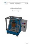
XtraforsPrime servomotor
SERVICE MANUAL
XtraforsPrime
Version 11.06
Version 11.06
Sheet 1 of 46
XtraforsPrime servomotor
Version 11.06
Sheet 2 of 46
XtraforsPrime servomotor
Contents
1.-Introduction to the product
2.-Safety Guideline
2.1.- Appropriate use
2.2.- Explanations
2.3.- Hazards by improper use
2.4.-Transport and storage
2.5 – Installation
2.6.- Protection against touching electrical parts
2.7.- Protection against dangerous movements
2.8.- Protection against contact with hot parts
2.9.- Protection during handling and mounting
3.- Technical data
3.1.- General description
3.2.- Definitions
3.3.- Characteristics
3.4.- Functional curve
3.5.- Cooling
3.6.- Brake functionality
3.7.- Grease life
3.8.- Shaft load
3.9.- Tolerances
4.- Dimensions
4.1.- Dimensions sheet
4.2.- Type of shaft end
4.3.- Keyed shaft
4.4.- Optional flange mounting
5.- Codification
6.- Installation
6.1.- Power connection
6.2.- Signal connection
6.3.- Connector position
7.- Conditions of use
7.1.- Ambient temperature
7.2.- Mechanical environmental conditions
7.2.1.- Vibration and Shock
7.2.1.- Enclosure protection IP
7.3 .- Balancing
8.- Accessories
8.1.-Cables
9.- Applications
9.1.- Process to select the servomotor
9.2.- Inertia calculations
9.3.- Torque calculations
Version 11.06
Sheet 3 of 46
Page
3
4
4
4
5
5
5
6
6
7
7
9
9
9
12
16
18
18
19
20
24
25
25
26
26
26
27
29
29
30
30
32
32
34
34
34
34
35
35
37
37
38
40
XtraforsPrime servomotor
Version 11.06
Sheet 4 of 46
XtraforsPrime servomotor
1.- Introduction to the Product
The XtraforsPrime servomotor is a new product generation that resumes all the knowhow and
the new technologies of Mavilor and the group Infranor.
The improvement can be found in the design, in the harmony with the drives, the performances
and optional solutions
Version 11.06
Sheet 5 of 46
XtraforsPrime servomotor
2. Safety Guidelines
2.1 Appropriate use
Servo motors have been designed, developed and manufactured for conventional use in the
industry. They were not designed, developed and manufactured for any use involving serious
risks or hazards that could lead to death, injury, serious physical damage, or
loss of any kind without the implementation of exceptionally stringent safety precautions.
Synchronous servomotors are precision motors. They are not intended to be connected directly to
a rotary current power supply system. They have to be operated only by a particular electronic
power stage. A direct connection to a main supply will lead to the destruction of the motor.
Personnel that in any way uses our products must first read and understand the relevant safety
instructions and be familiar with appropriate use.
Do not mount damaged or faulty products or use them in operation.
Make sure that the products have been installed in the manner described in the relevant
documentation.
Servo motors can have bare parts with voltages applied (e.g. terminals) or hot surfaces.
Additional sources of danger result from moving machine parts. Improperly removing the
required covers, inappropriate use, incorrect installation or incorrect operation can result in
severe personal injury or damage to property.
2.2.-Explanations
The safety instructions describe the following degrees of hazard seriousness in compliance with
ANSI Z535.4. The degree of hazard seriousness informs about the consequences resulting from
noncompliance with the safety instructions.
Signal Word
Version 11.06
Definition
DANGER indicates an imminently hazardous
situation which, if not avoided, will result in death or
serious injury. This signal word is to be limited to the
most extreme situations
WARNING indicates a potentially hazardous
situation which, if not avoided, could result in death
or serious injury
CAUTION indicates a potentially hazardous
situation which, if not avoided, may result in minor
or moderate injury. It may also be used to alert
against unsafe practices
Sheet 6 of 46
XtraforsPrime servomotor
2.3 Hazards by Improper Use
High voltage and High discharge current! Danger to
life or severe bodily harm by electric shock
Dangerous movements! Danger to life severe bodily
harm or material damage by an unintentional motor
movement
High electrical voltage due to wrong connections!
Danger to life or bodily harm by electric shock
Health hazard for persons with heart pacemakers,
metal implants and hearing aids in proximity to
electrical equipment!
Surface of machine housing could be extremely hot!
Danger of injury! Danger of burns!
Risk of injury due to improper handling! Bodily harm
caused by crushing, shearing, cutting and mechanical
shock
2.4 Transport and Storage
During transport and storage, devices must be protected from excessive stress ( mechanical load,
temperature, humidity, aggressive atmosphere, etc.).
Servo drives contain components sensitive to electrostatic charges which can be damaged by
inappropriate handling. It is therefore necessary to provide the required safety precautions
against electrostatic discharges during installation or removal of servo drives.
2.5 Installation
The installation must take place according to the service manual using suitable equipment and
tools.
Devices may only be installed without voltage applied and by qualified personnel. Before
installation, voltage to the switching cabinet should be switched off and prevented from being
switched on again.
The general safety regulations and national accident prevention guidelines (Council Directive
89/391/CEE) must be observed when working with high voltage systems.
Electrical installation must be carried out according to the relevant guidelines (e.g. line cross
section, fuse, protective ground connection).
High voltage and High discharge current! Danger to
life or severe bodily harm by electric shock
Version 11.06
Sheet 7 of 46
XtraforsPrime servomotor
2.6 Protection against Touching Electrical Parts
Before turning on a servo drive, make sure that the housing is properly connected to ground (PE
rail). The ground connection must be made, even when testing the servo drive or when operating
it for a short time!
Before turning the device on, make sure that all voltage-carrying parts are securely covered.
During operation, all covers and switching cabinet doors must remain closed.
Control and high power contacts can have voltage applied, even when the motor is not turning.
Touching the contacts when the device is switched on is not permitted.
Before working on servo drives, they must be disconnected from the power mains and prevented
from being switched on again.
The servo drives are labelled with the following warning:
High electrical voltage due to wrong connections!
Danger to life or bodily harm by electric shock
2.7 Protection against Dangerous Movements
Dangerous movements can be caused by faulty control of the connected motors.
Some common examples are:
- improper or wrong wiring of cable connections
- incorrect operation of the equipment components
- wrong input of parameters before operation
- malfunction of sensors, encoders and monitoring devices
- defective components
- software or firmware errors
Dangerous movements can occur immediately after equipment is switched on or even after an
unspecified time of trouble-free operation.
The monitoring in the drive components will normally be sufficient to avoid faulty operation in
the connected drives. Regarding personal safety, especially the danger of bodily injury and
material damage, this alone cannot be relied upon to ensure complete safety. Until the integrated
monitoring functions become effective, it must be assumed in any case that faulty drive
movements will occur. The extent of faulty drive movements depends upon the type of control
and the state of operation.
Dangerous movements! Danger to life severe bodily
harm or material damage by motor unintentional
movement
- Ensure personal safety by means of qualified and tested higher-level monitoring devices or
measures integrated in the installation. Unintended machine motion is possible if monitoring
devices are disabled, bypassed or not activated.
- Pay attention to unintended machine motion or other malfunction in any mode of operation.
- Keep free and clear of the machine’s range of motion and moving parts. Possible measures to
prevent people from accidentally entering the machine’s range
of motion:
- use safety fences
Version 11.06
Sheet 8 of 46
XtraforsPrime servomotor
- use safety guards
- use protective coverings
- install light curtains or light barriers
- Fences and coverings must be strong enough to resist maximum possible momentum,
especially if there is a possibility of loose parts flying off.
- Mount the emergency stop switch in the immediate reach of the operator. Verify that the
emergency stop works before starting up. Do not operate the machine if the emergency stop is
not working.
- Isolate the drive power connection by means of an emergency stop circuit or use a starting
lockout to prevent unintentional start.
- Make sure that the drives are brought to a safe standstill before accessing or entering the danger
zone. Safe standstill can be achieved by switching off the power supply contactor or by safe
mechanical locking of moving parts.
- Secure vertical axes against falling or dropping after switching off the motor power by, for
example:
- mechanically securing the vertical axes
- adding an external braking/ arrester/ clamping mechanism
- ensuring sufficient equilibration of the vertical axes
The standard equipment motor brake or an external brake controlled directly by the drive
controller is not sufficient to guarantee personal safety!
2.8 Protection against Contact with Hot Parts
Surface of machine housing could be extremely hot!
Danger of injury! Danger of burns!
- Do not touch housing surfaces near sources of heat!
- After switching off the equipment, wait at least ten (10) minutes to allow it to cool down before
touching it.
- Do not touch hot parts of the equipment, such as housings with integrated heat sinks and
resistors.
2.9 Protection during Handling and Mounting
Under certain conditions, incorrect handling and mounting of parts and components may cause
injuries.
Risk of injury due to improper handling! Bodily
harm caused by crushing, shearing, cutting and
mechanical shock
- Observe general installation and safety instructions with regard to handling and mounting.
- Use appropriate mounting and transport equipment.
- Take precautions to avoid pinching and crushing.
- Use only appropriate tools. If specified by the product documentation, special tools must be
used.
Version 11.06
Sheet 9 of 46
XtraforsPrime servomotor
- Use lifting devices and tools correctly and safely.
- For safe protection wear appropriate protective clothing, e.g. safety glasses, safety shoes and
safety gloves.
- Never stand under suspended loads.
- Clean up liquids from the floor immediately to prevent slipping.
Version 11.06
Sheet 10 of 46
XtraforsPrime servomotor
3.- Technical Data
3.1.- General Description
The three-phase synchronous motors from the XtraforsPrime are permanently excited,
electronically commutated synchronous motors for applications that require excellent dynamic
characteristics and positioning precision as well as compact size and reduced weight.
• NdFeB permanent magnets
• Sinusoidal commutation with encoder or resolver as feedback unit
• Three-phase winding with star connection
• Compact sizes result in low weight
• High overload capability/peak torque
• 0 Cogging torque due to it’s special construction without slots in the stator
• High dynamic torque at high speeds
• Long life-span, all motor parts except for bearings are free of wear
• Direct diversion of lost power generated in the stator over the housing to the flange
• Preloaded, grooved ball bearings which are sealed on both sides and greased
• Complete motor system with stall torque ranging from 0.25 Nm to 75 Nm
• Connection using two circular plugs or cables
3.2.- Definitions
Max speed
The speed limit is fixed by the bus voltage of the drive
The value is given in RPM
Stall torque
The torque is given by the motor at very low speed, with an increment of the winding
temperature of 130ºC and mounted with a heat sink plate.
The value is given in Nm
Stall current
The current is required to achieve the stall torque
The value is given in A
Peak torque
The maximum torque is available without iron saturation (torque constant still linear)
The value is given in Nm
Version 11.06
Sheet 11 of 46
XtraforsPrime servomotor
EMF constant
Voltage that the motor gives as a generator between two terminals at certain speed, the voltage is
measured in rms value and the speed in rad/s
The value is given in Vs/rad
Torque constant
The ratio between the current (in rms value) is supplied to the motor and the torque in the output
shaft, measured in Nm
The value is given in Nm/A
Reluctance torque (Cogging)
The maximum torque needed to move the shaft without power. It characterizes the stepping
effect of the rotor which should be as low as possible.
The value is given in Nm
Winding resistance
The resistance is measured between two phases at 25ºC T ambient
The values is given in
Winding inductance
The inductance is measured between two phases
The value is given in mH
Rotor inertia
It is inertia of the rotor without any accessories.
The value is given in kg m210-3
Version 11.06
Sheet 12 of 46
XtraforsPrime servomotor
Mechanical time constant
It characterizes the speed increase for an input voltage step. The value shows the time to achieve
the 63% of the maximum speed for the input voltage.
w
100%
75%
U
Ke
Tm
JxR
KexKt
50%
25%
0%
0
Tm
33,3
66,6
99,9 t
The values is given in s
Electrical time constant
It characterizes the current increase in the motor winding for a voltage step
I
100%
75%
U
R
Te
50%
L
R
25%
0%
0
33,3
66,6
Te
99,9 t
The value is given in ms when L is in mH and R in
Thermal resistance
It is the temperature difference across a structure when a unit of heat energy flows through it in
unit time
The value is given in ºC/W
Version 11.06
Sheet 13 of 46
XtraforsPrime servomotor
Mass
It is the weight of the motor without accessories. The value is given in kg
Radial load
It expresses the shaft radial load applied in the middle of the output shaft, which will give a basic
rating life of the bearings of 20000 hours
Axial load
It expresses the shaft axial load which will give a basic rating life of the bearings of 20000 hours
Insulation
It refers to the maximum operation temperature allowed
3.3.- Characteristics
400 VAC
CHARACTERISTICS
SYMBOL
UNITS
FP-0023
FP-0034
FP-0055
FP-0105
FP-0207
FP-0307
Max. Speed at 400V (± 10%)
rpm
nm
36000(1)
30000(1)
22000(2)
15000
9500
8500
Stall Torque (± 10%)
Ms
Nm
0.24
0.40
0.54
1
2
2.7
Stall Current (± 10%)
Is
A
1.40
1.49
2.15
2.51
3.04
3.63
Nominal Torque at 3000rpm (3)
Mn
Nm
0.23
0.38
0.46
0.9
1.85
2.54
Peak Torque (± 10%)
Mj
Nm
1.44
2.4
3.24
6
12
16.2
EMF Constant (±5%)
Ke
Vs/rad
0.099
0.155
0.145
0.23
0.38
0.43
Torque Constant (±5%)
Kt
Nm/A
0.17
0.27
0.25
0.40
0.66
0.74
Cogging Torque
Ct
Nm
0
0
Winding Resistance (± 5%)
R
Ω
10
14.7
0
9.7
0
9.2
0
8.2
0
6.2
Winding Inductance (± 5%)
L
mH
2
4.34
2.5
2.45
3.4
2.6
Rotor Inertia
J
kgm²10-³
0.0033
0.01
0.02
0.04
0.13
0.19
Tm
ms
1.94
3.53
5.33
4.02
4.26
3.68
Electrical Time Constant
Te
ms
0.200
0.295
0.258
0.266
0.415
0.419
Thermal Time Constant (5)
Tth
s
661
712
855
588
980
1126
Thermal Resistance
Rth
ºc/W
2.97
1.78
1.30
1.00
0.77
0.71
F
F
F
F
F
F
155
155
155
155
155
155
4
4
8
8
8
8
Mechanical Time Constant
Insulation
Max. winding temperature
ºc
Nº of poles
Axial force
Fa
N
40
80
100
100
120
120
Radial force
Fr
N
75
150
230
250
338
367
Weight
M
kg
Temperature sensor type
With an Aluminium heat sink plate
(4)
Version 11.06
mm
0.4
0.7
1
1.2
2.1
2.5
PTC
PTC
PTC
PTC
PTC
PTC
150x150
300x300
300x300
300x300
300x300
300x300
Sheet 14 of 46
XtraforsPrime servomotor
CHARACTERISTICS
SYMBOL
UNITS
FP-0409
FP-0609
FP-0711
FP-0911
FP-1111
FP-1311
Max. Speed at 400V (± 10%)
rpm
nm
5300
5500
6300
5000
4600
4600
Stall Torque (± 10%)
Ms
Nm
4.2
5.6
6.5
9
11
13.2
Is
A
3.57
4.97
6.82
7.99
8.14
9.77
Mn
Nm
4.15
5.12
6.10
8.20
9.10
10.75
Stall Current (± 10%)
Nominal Torque at 3000rpm (3)
Peak Torque (± 10%)
Mj
Nm
25.2
33.6
39
54
66
79.2
EMF Constant (±5%)
Ke
Vs/rad
0.68
0.65
0.55
0.65
0.78
0.78
Torque Constant (±5%)
Kt
Nm/A
1.18
1.13
0.95
1.13
1.35
1.35
Cogging Torque
Ct
Nm
0
0
0
0
0
0
Winding Resistance (± 5%)
R
Ω
6.5
4.1
2.84
2.4
1.91
1.9
Winding Inductance (± 5%)
L
mH
3.8
2.4
2.4
2.29
2.07
2
Rotor Inertia
J
kgm²10-³
0.48
0.63
1.16
1.72
2.28
2.85
Tm
ms
3.90
3.53
6.29
5.64
4.13
5.14
Electrical Time Constant
Te
ms
0.585
0.585
0.845
0.954
1.084
1.053
Thermal Time Constant (5)
Tth
s
1005
1108
992
1157
1340
1604
Thermal Resistance
Rth
ºc/W
0.70
0.57
0.44
0.38
0.46
0.32
F
F
F
F
F
F
ºc
155
155
155
155
155
155
8
8
8
8
8
8
N
160
160
200
200
200
200
685
Mechanical Time Constant
Insulation
Max. winding temperature
Nº of poles
Axial force
Fa
Radial force
Fr
N
572
606
550
600
650
Weight
M
kg
4.2
4.3
5.6
7
8.3
9.6
PTC
PTC
PTC
PTC
PTC
PTC
mm
400x400
400x400
500x500
500x500
500x500
500x500
Temperature sensor type
With an Aluminium heat sink plate
(4)
CHARACTERISTICS
SYMBOL
UNITS
FP-1714
FP-3314
FP-5019
FP-8019
Max. Speed at 400V (± 10%)
rpm
nm
3500
2500
2000
2000
Stall Torque (± 10%)
Ms
Nm
18.3
31.5
54.5
75
Stall Current (± 10%)
Is
A
10.67
13.37
19.07
22.79
Nominal Torque at 3000rpm (3)
Mn
Nm
15.50
27.50
46.00
59.00
Peak Torque (± 10%)
Mj
Nm
109.8
189
327
450
EMF Constant (±5%)
Ke
Vs/rad
0.99
1.36
1.65
1.9
Torque Constant (±5%)
Kt
Nm/A
1.71
2.36
2.86
3.29
Cogging Torque
Ct
Nm
0
0
0
0
Winding Resistance (± 5%)
R
Ω
1.23
1.28
0.8
0.83
Winding Inductance (± 5%)
L
mH
2.6
2.1
2
2.1
Rotor Inertia
J
kgm²10-³
6.02
12.01
28.3
37.7
Mechanical Time Constant
Tm
ms
4.36
4.80
4.80
5.00
Electrical Time Constant
Te
ms
2.114
1.641
2.500
2.530
Thermal Time Constant (5)
Tth
s
2249
2948
2407
2555
Thermal Resistance
Rth
ºc/W
0.41
0.25
0.20
0.13
F
F
F
F
155
155
155
155
8
8
12
12
Insulation
Max. winding temperature
ºc
Nº of poles
Axial force
Fa
N
360
360
700
700
Radial force
Fr
N
770
950
1500
1600
Weight
M
kg
Temperature sensor type
With an Aluminium heat sink plate
(4)
Version 11.06
mm
14.2
23.2
32
41
PTC
PTC
PTC
PTC
700x700
700x700
700x700
700x700
Sheet 15 of 46
XtraforsPrime servomotor
230 VAC
CHARACTERISTICS
SYMBOL
UNITS
FP-0023
FP-0034
FP-0055
FP-0105
FP-0207
FP-0307
Max. Speed at 230V (± 10%)
rpm
nm
27000(1)
30000(1)
16300(2)
11400
8700
6600
Stall Torque (± 10%)
Ms
Nm
0.24
0.4
0.54
1
2
2.7
Stall Current (± 10%)
Is
A
1.97
2.98
2.67
3.45
5.28
5.44
Nominal Torque at 3000rpm (3)
Mn
Nm
0.23
0.38
0.46
0.9
1.85
2.54
Peak Torque (± 10%)
Mj
Nm
1.44
2.4
3.24
6
12
16.2
EMF Constant (±5%)
Ke
Vs/rad
0.07
0.077
0.12
0.17
0.22
0.29
Torque Constant (±5%)
Kt
Nm/A
0.12
0.13
0.20
0.29
0.38
0.50
Cogging Torque
Ct
Nm
0
0
Winding Resistance (± 5%)
R
W
5.1
3.7
0
6.2
0
4.8
0
2.7
0
2.8
Winding Inductance (± 5%)
L
mH
1.0
1.1
1.6
1.3
1.1
1.2
Rotor Inertia
J
kgm²10-³
0.0033
0.01
0.02
0.04
0.13
0.19
Mechanical Time Constant
Tm
ms
1.97
3.53
5.28
3.95
4.27
3.68
Electrical Time Constant
Te
ms
0.197
0.295
0.260
0.271
0.414
0.419
Thermal Time Constant (5)
Tth
s
661
712
855
588
980
1126
Thermal Resistance
Rth
ºc/W
2.93
1.78
1.31
1.02
0.77
0.71
F
F
F
F
F
F
155
155
155
155
155
155
4
4
8
8
8
8
Insulation
Max. winding temperature
ºc
Nº of poles
Axial force
Fa
N
40
80
100
100
120
120
Radial force
Fr
N
75
150
230
250
338
367
Weight
M
kg
0.4
0.7
1
1.2
2.1
2.5
PTC
PTC
PTC
PTC
PTC
PTC
150x150
300x300
300x300
300x300
300x300
300x300
Temperature sensor type
With an Aluminium heat sink plate (4)
CHARACTERISTICS
SYMBOL
mm
UNITS
FP-0409
FP-0609
FP-0711
FP-0911
FP-1111
FP-1311
FP-1714
Max. Speed at 230V (± 10%)
rpm
nm
5000
3800
4800
3800
3500
3200
3100
Stall Torque (± 10%)
Ms
Nm
4.2
5.6
6.5
9
11
13.2
18.3
Stall Current (± 10%)
Is
A
6.46
6.53
9.46
11.63
11.76
13.03
17.34
Nominal Torque at 3000rpm (3)
Mn
Nm
4.15
5.12
6.10
8.20
9.10
10.75
15.50
Peak Torque (± 10%)
Mj
Nm
25.2
33.6
39
54
66
79.2
109.8
EMF Constant (±5%)
Ke
Vs/rad
0.38
0.50
0.39
0.44
0.54
0.59
0.61
Torque Constant (±5%)
Kt
Nm/A
0.65
0.86
0.67
0.77
0.94
1.01
1.06
Cogging Torque
Ct
Nm
0
0
0
0
0
0
0
Winding Resistance (± 5%)
R
W
2.0
2.4
1.5
1.1
0.9
1.1
0.5
Winding Inductance (± 5%)
L
mH
1.2
1.4
1.2
1.1
1.0
1.1
1.0
Rotor Inertia
J
kgm²10-³
0.48
0.63
1.16
1.72
2.28
2.85
6.02
Tm
ms
3.84
3.53
6.42
5.64
4.15
5.10
4.40
Electrical Time Constant
Te
ms
0.593
0.585
0.828
0.955
1.080
1.061
2.097
Thermal Time Constant (5)
Tth
s
1005
1108
992
1157
1340
1604
2249
Thermal Resistance
Rth
ºc/W
0.71
0.57
0.43
0.38
0.46
0.32
0.41
F
F
F
F
F
F
F
155
155
155
155
155
155
155
8
8
8
8
8
8
8
360
Mechanical Time Constant
Insulation
Max. winding temperature
ºc
Nº of poles
Axial force
Fa
N
160
160
200
200
200
200
Radial force
Fr
N
572
606
550
600
650
685
770
Weight
M
kg
4.2
4.3
5.6
7
8.3
9.6
14.2
PTC
PTC
PTC
PTC
PTC
PTC
PTC
mm
400x400
400x400
500x500
500x500
500x500
500x500
700x700
Temperature sensor type
With an Aluminium heat sink plate (4)
Version 11.06
Sheet 16 of 46
XtraforsPrime servomotor
48 VDC
CHARACTERISTICS
Max. Speed at 48VDC (± 10%)
Stall Torque (± 10%)
Stall Current (± 10%)
Nominal Torque at 3000rpm (3)
Peak Torque (± 10%)
EMF Constant (±5%)
Torque Constant (±5%)
Cogging Torque
Winding Resistance (± 5%)
Winding Inductance (± 5%)
Rotor Inertia
Mechanical Time Constant
Electrical Time Constant
Thermal Time Constant (5)
Thermal Resistance
Insulation
Max. winding temperature
Nº of poles
Axial force
Radial force
Weight
Temperature sensor type
With an Aluminium heat sink plate (4)
SYMBOL
rpm
Ms
Is
Mn
Mj
Ke
Kt
Ct
R
L
J
Tm
Te
Tth
Rth
UNITS
nm
Nm
A
Nm
Nm
Vs/rad
Nm/A
Nm
W
mH
kgm²10-³
ms
ms
s
ºc/W
ºc
Fa
Fr
M
N
N
kg
mm
FP-0023
6000
0.24
2.80
0.23
1.44
0.05
0.09
0
2.5
0.5
0.0033
1.94
0.200
661
2.97
F
155
4
40
75
0.4
PTC
150x150
FP-0034
6000
0.4
3.83
0.38
2.4
0.06
0.10
0
2.2
0.7
0.01
3.48
0.300
712
1.81
F
155
4
80
150
0.7
PTC
300x300
FP-0055
4500
0.54
4.64
0.46
3.24
0.07
0.12
0
2.1
0.5
0.02
5.40
0.254
855
1.28
F
155
8
100
230
1
PTC
300x300
FP-0105
3000
1
6.37
0.9
6
0.09
0.16
0
1.4
0.4
0.04
4.08
0.262
588
0.99
F
155
8
100
250
1.2
PTC
300x300
(1) 25000 rpm values achievable with GD1 & CD1 Drive (Speed Limit Converter)
(2) 15000 rpm values achievable with GD1 & CD1 Drive (Max. Current Bandwidth, 1KHz)
(3) From FP-1714 to big sized, Nominal Torque at 1500rpm
(4) From FP-1714 to big sized, the width size is 20mm, the rest 10mm.
(5) With heat sink included
When the motor is mounted with encoder, the performances could be changed because of the temperature or speed limit of the
electronics, please ask factory for more details.
Version 11.06
Sheet 17 of 46
FP-0207
3000
2
12.53
1.85
12
0.09
0.16
0
0.5
0.2
0.13
4.36
0.405
980
0.75
F
155
8
120
338
2.1
PTC
300x300
XtraforsPrime servomotor
3.4.- Functional curves
The curves shown here below, have been obtained with a CD1a 400VAC drive. The motors were
mounted in a heat sink plate of aluminium see table 4 and with an increment of temperature on
the winding of 130º at 25ºC Amb.
Version 11.06
FP-0023 (CD1a 5.1)
FP-0034
FP-0055
(CD1a 5.1)
FP-0105
FP-0207
(CD1a 7.2)
FP-0307
Sheet 18 of 46
(CD1a 5.1)
(CD1a 5.1)
(CD1a 7.2)
XtraforsPrime servomotor
FP-0409
(CD1a 7.2)
FP-0711
(CD1a 14)
FP-1111
FP-1714
Version 11.06
(CD1a 30)
FP-0609
FP-0911
FP-1311
(CD1a 30)
Sheet 19 of 46
FP-3314
(CD1a 14)
(CD1a 30)
(CD1a 30)
(CD1a 30)
XtraforsPrime servomotor
FP-5019
(CD1a 45)
FP-8019
(CD1a 45)
3.5.- Cooling
The XtraforsPrime motor are self-cooling. The motors must be installed on the cooling surface
equivalent to the aluminium heat sink according to the following table
.
Motor
FP-0023
FP-0034
FP-0055
FP-0105
FP-0207
FP-0307
FP-0409
FP-0609
Heat Sink Plate
150*150*10
300*300*10
300*300*10
300*300*10
300*300*10
300*300*10
400*400*10
400*400*10
Motor
FP-0711
FP-0911
FP-1111
FP-1311
FP-1714
FP-3314
FP-5019
FP-8019
Heat Sink Plate
500*500*20
500*500*20
500*500*20
500*500*20
700*700*20
700*700*20
700*700*20
700*700*20
Table 4
Free convection of the motor housing must
be guaranteed!
3.6.- Brake functionality
The XtraforsPrime motors can be supplied with a holding brake
Motor
FP-0023
FP-0034
FP-0055
FP-0105
FP-0207
FP-0307
FP-0409
FP-0609
-
-
1
1
2
4,5
4,5
9
10
10
11
12
12
18
Inertia 10 kgm
0.021
0.021
0.068
0.18
0.18
0.54
Weight kg
0.11
0.11
0.15
0.30
0.30
0.46
Brake torque Nm
Power W
-4
2
Motor
FP-0711
FP-0911
FP-1111
FP-1311
FP-1714
FP-3314
FP-5019
FP-8019
Brake torque Nm
9
9
18
18
18
36
72
72
Power W
18
18
24
24
24
26
40
40
Inertia 10 kgm
0.54
0.54
1.66
1.66
1.66
5.56
11.5
11.5
Weight kg
0.46
0.46
0.9
0.9
0.9
1.6
2.85
2.85
-4
2
Table 5
Version 11.06
Sheet 20 of 46
XtraforsPrime servomotor
Release voltage vs brake air gap and motor temperature
3.7.- Grease life
Test item
Appearance
Thickener
Worked penetration
Dropping point ºC
Copper strip corrosion
Evaporation loss mass %
100ºC, 24h
99ºC, 22h
Oil separation mass%
Oxidation stability Mpa
100ºC, 24h
99ºC, 100h
10 um or larger
25 um or larger
75 um or larger
125 um or larger
Foreign particles particles/cm 3
Working stability
Water washout mass%
Low-temperature torque Ncm
Corrosion preventive properties
2
Base oil kinematics viscosity mm /s
38ºC,1h
Starting torque
-30ºC Running torque
Starting torque
-40ºC Running torque
52ºC, 48h
40ºC
Multemp SRL
light brown,
buttery
Lithium soap
250
190
pass
0.3
1.2
0.025
400
100
0
0
305
1.3
7.9
2.5
11
2.8
#1
26
Test method
ASTM D217
ASTM D566
ASTM D4048
ASTM D972
ASTM D6184-98
Mod.
ASTM D942
ASTM D1264
ASTM D1478-63
ASTM D1743-73
ASTM D445
Other greases are available for different temperatures, please ask factory for more information
Version 11.06
Sheet 21 of 46
XtraforsPrime servomotor
3.8.- Shaft Load
Axial force
The axial force Fa on the shaft end is made up of the installation forces (e.g. stress caused by
installation) and operational forces (e.g. thrust caused by slanted pinions). The maximum axial
force Fa depends on the bearing type and the desired lifespan of the bearings.
The fixed bearing is secured on the B flange with a retaining plate. The floating ball bearing is
preloaded on the A flange with a spring in the direction of the B flange. Axial forces in the
direction of the A flange can cause the spring bias to be overcome and the shaft is shifted by the
amount of axial play in the bearing (0.1 to 0.2 mm approx). This shift can cause problems on
motors with holding brakes or motors with encoders.
Because of the high axial forces on the motor shaft during installation, the
bearings could be damaged and the operation of the motor holding brake
could be so heavily influenced that it has no or only a reduced braking effect.
Encoder errors could also occur.
Therefore, excessive pressure or shocks to the front of the shaft end or the
rear housing cover should be avoided at all costs.
Loads caused by a hammer definitely exceed the permissible values!
Radial force
The radial force Fr on the shaft end is made up of installation forces (e.g. belt tension on pulleys)
and operation forces (e.g. load torque on the pinion). The maximum radial force Fr depends on
the shaft end type, bearing type, average speed, position where the radial force is applied and the
desired lifespan of the bearing. As standard 20000 h when the load indicated on the catalogue is
applied in the middle of the output shaft.
Excessive radial force can cause premature wear on the bearing or, in extreme
cases, can cause the output shaft to break
Version 11.06
Sheet 22 of 46
XtraforsPrime servomotor
When installing drive elements on the motor shaft avoid hyperstatic
arrangements of the motor shaft bearing. The tolerances that occurs cause
additional force on the motor shaft bearings
This can significantly reduce the bearing lifespan or damage the bearing.
Shaft Load vs position
Radial load FP_0034
Rear Ball Bearing
450
400
350
400
350
300
300
250
200
150
Rear Ball Bearing
250
200
150
100
100
50
50
0
0
0
5
10
15
20
0
25
Radial load FP_0105
10
15
Radial load FP_0207
Frontal Ball Bearing
3000 rpm
(lifetime 20000 hours)
500
5
20
Distance on output shaft between load application point
and output flange (mm)
Distance on output shaft between load application point
and output flange (mm)
Rear Ball Bearing
3000 rpm
(lifetime 20000 hours)
800
450
Frontal Ball Bearing
Rear Ball Bearing
700
400
350
600
300
Fr (N)
Fr (N)
Frontal Ball Bearing
3000 rpm
(lifetime 20000 hours)
500
450
Fr (N)
Fr (N)
500
Radial load FP_0055
Frontal Ball Bearing
3000 rpm
(lifetime 20000 hours)
250
200
150
500
400
300
200
100
100
50
0
0
0
5
10
15
20
Distance on output shaft between load application point
and output flange (mm)
Version 11.06
Sheet 23 of 46
0
5
10
15
20
Distance on output shaft between load application point
and output flange (mm)
XtraforsPrime servomotor
Radial load FP_0307
800
Radial load FP_0409
Frontal Ball Bearing
3000 rpm
(lifetime 20000 hours)
Rear Ball Bearing
1250
700
Fr (N)
Fr (N)
500
400
300
200
750
500
250
100
0
0
0
5
10
15
20
0
Distance on output shaft between load application point
and output flange (mm)
Radial load FP_0609
10
20
30
40
Distance on output shaft between load application point
and output flange (mm)
Radial load FP_0711
Frontal Ball Bearing
3000 rpm
(lifetime 20000 hours)
1250
Rear Ball Bearing
Frontal Ball Bearing
3000 rpm
(lifetime 20000 hours)
1500
Rear Ball Bearing
1250
1000
1000
750
Fr (N)
Fr (N)
Rear Ball Bearing
1000
600
500
250
750
500
250
0
0
0
10
20
30
40
0
Distance on output shaft between load application point
and output flange (mm)
Radial load FP_0911
10
20
30
40
Distance on output shaft between load application point
and output flange (mm)
Radial load FP_1111
Frontal Ball Bearing
3000 rpm
(lifetime 20000 hours)
1500
Rear Ball Bearing
1250
1250
1000
1000
750
500
250
Frontal Ball Bearing
3000 rpm
(lifetime 20000 hours)
1500
Fr (N)
Fr (N)
Frontal Ball Bearing
3000 rpm
(lifetime 20000 hours)
Rear Ball Bearing
750
500
250
0
0
0
10
20
30
40
Distance on output shaft between load application point
and output flange (mm)
Version 11.06
Sheet 24 of 46
0
10
20
30
Distance on output shaft between load application point
and output flange (mm)
40
XtraforsPrime servomotor
Radial load FP_1311
1500
Radial load FP_1714
Frontal Ball Bearing
3000 rpm
(lifetime 20000 hours)
Rear Ball Bearing
2000
Rear Ball Bearing
1500
Fr (N)
1000
750
500
1250
1000
750
500
250
250
0
0
0
10
20
30
40
0
Distance on output shaft between load application point
and output flange (mm)
Radial load FP_3314
10
20
30
40
50
Distance on output shaft between load application point
and output flange (mm)
Radial load FP_5019
Frontal Ball Bearing
1500 rpm
(lifetime 20000 hours)
2000
Rear Ball Bearing
1500 rpm
(lifetime 20000 hours)
3000
1750
Frontal Ball Bearing
Rear Ball Bearing
2500
1500
2000
Fr (N)
1250
1000
750
500
1500
1000
500
250
0
0
0
10
20
30
40
50
0
Distance on output shaft between load application point
and output flange (mm)
10
1500 rpm
(lifetime 20000 hours)
3000
Frontal Ball Bearing
Rear Ball Bearing
2500
2000
1500
1000
500
0
0
10
20
30
40
50
Distance on output shaft between load application point
and output flange (mm)
Version 11.06
20
30
40
50
Distance on output shaft between load application point
and output flange (mm)
Radial load FP_8019
Fr (N)
Fr (N)
Frontal Ball Bearing
1750
1250
Fr (N)
3000 rpm
(lifetime 20000 hours)
Sheet 25 of 46
XtraforsPrime servomotor
3.9.- Tolerances IEC 60072
Shaft extension run-out
Shaft diameter
Normal
Reduced
0 < D ≤ 10
0.030
0.015
10 < D ≤ 18
0.035
0.018
18 < D ≤ 30
0.040
0.021
Concentricity and Perpendicularity
Mounting flange diameter
32
40
60
80
95
130
Version 11.06
Normal
Reduced
0.08
0.08
0.08
0.08
0.08
0.10
0.04
0.04
0.04
0.04
0.04
0.05
Sheet 26 of 46
XtraforsPrime servomotor
4.- Dimensions
4.1.- Dimensions sheet
FP-0023
FP-0034
FP-0055
FP-0105
FP-0207
FP-0307
FP-0409
FP-0609
FP-0711
FP-0911
FP-1111
FP-1311
FP-1714
FP-3314
FP-5019
FP-8019
INCREMENTAL
END DAT 2.1
HIPERFACE
SinCos
ØAj6
ØB
4xØC
ØDk6
E
F
G
G1
□H
I
J0 +0.1
K
28
40
4.5
8j5
25
-
2.5
5
38
-
-
48
32
45
4.5
8j5
25
-
2.5
5
42
-
-
70
40
65
5.5
9
20
M3x9
2.5
5.5
57
A3x3x12
10.2
107
40
65
5.5
9
20
M3x9
2.5
5.5
57
A3x3x12
10.2
60
75
5.5
11
23
M4x10
2.5
7
70
A4x4x14
60
75
5.5
11
23
M4x10
2.5
7
70
80
100
6.6
19
40
M6x16
3
9
80
100
6.6
19
40
M6x16
3
95
115
9
19
40
M6x16
95
115
9
19
40
M6x16
95
115
9
19
40
95
115
9
19
130
165
11
130
165
180
180
L1
ØM
125
160
48
140.5
171.5
53
90
129
74
107
110
149
74
12.5
112
116.5
142
89
A4x4x14
12.5
112
137.5
165.5
89
90
A6x6x30
21.5
132
147.5
177
111
9
90
A6x6x30
21.5
132
165.5
210
111
3
9
110
A6x6x30
21.5
152
149
194
130
3
9
110
A6x6x30
21.5
152
173
218
130
M6x16
3
9
110
A6x6x30
21.5
152
197
242
130
40
M6x16
3
9
110
A6x6x30
21.5
152
221
266
130
24
50
M8x19
3.5
12
140
A8x7x32
27
182
215
258
184
11
24
50
M8x19
3.5
12
140
A8x7x32
27
182
317
367
184
215
16
32
58
M12x28
4
19.5
192
A10x8x50
35
247
297.5
383
240
215
16
32
58
M12x28
4
19.5
192
A10x8x50
35
247
348.5
434
240
FP-0023
L
L1
(**) (**)
-
FP-0034
L
L1
(**) (**)
-
FP-00711
L
L1
INCREMENTAL
END DAT 2.1
HIPERFACE
SinCos
Version 11.06
162
185.5
172.5
181
197
220.5
205.5
220.5
FP-0055
L
L1
112.5 145
123
167
123
156
137
172
FP-0911
L
L1
186
209.5
196.5
205
221
244.5
229.5
244.5
FP-0105
L
L1
132.5 165
143
187
143
179
157
192
FP-1111
L
L1
210
233.5
220.5
229
258
281.5
268.5
281.5
FP-0207
L
L1
116.5 162
159
190
142
173
159
190
FP-1311
L
L1
234
257.5
244.5
253
Sheet 27 of 46
282
305.5
292.5
305.5
FP-0307
L
L1
137.5 189
180
217
163
200
180
217
FP-1714
L
L1
223
266
258
265
296.5
322.5
304
318.5
FP-0409
L
L1
147.5
192
185.5
215
158
202.5
177
215
FP-3314
L
L1
325
368
360
367
L
398.5
424.5
406
420.5
FP-5019
L
L1
310.5
317.5
317.5
322.5
363
368
368
373
FP-0609
L
L1
165.5
215
203.5
245
176
225.5
195
244.5
FP-8019
L
L1
361.5
368.5
368.5
373.5
414
419
419
424
XtraforsPrime servomotor
4.2.- Type of Output Shaft
All the XtraforsPrime servomotor shafts comply to DIN 748. They can be supplied with a
smooth shaft or keyed shaft. The NEMA option is also available.
Smooth shaft
A smooth output shaft is used for a force-fit shaft-hub connection that guarantees a zero –play
connection between shaft and hub as well as smooth operation.
For connection of pinion gears, belt disks or similar drive elements, please use suitable clamping
sets, pressure sleeves or other fastening elements
Drive elements must be protected against unintentional removal
The output shaft has a threaded centre hole which can be used to remove drive elements
4.3.- Keyed shaft
The keyed shaft can be used for a form-fit torque transfer with low demands on the shaft-hub
connection and for handling torques with a constant direction.
The keyways for the XtraforsPrime servomotors conform to keyway form N1 according to DIN
6885-1. Form A Shaft keys used conforms to DIN 6885-4 . Balancing motors with keyways is
done using the half-key convention according to ISO 2372
The end of the shaft has a threaded centre hole which can be used to mount drive elements with
shaft end disks.
The shaft key can be deflected during heavy reverse operation. In extreme
cases, this can cause the output shaft to break!
Smooth output shaft should be used preferably
4.4.- Optional flange mounting
The NEMA mounting flange is an option available, for other configuration contact factory.
Version 11.06
Sheet 28 of 46
XtraforsPrime servomotor
5.- Codification
Version 11.06
Sheet 29 of 46
XtraforsPrime servomotor
1.- Stall Torque
2.-Peak Torque
3.-Motor Type
4.- Voltage constant
5.- Torque constant
6.- Nominal speed
7.- Supply voltage of the drive
8.- Power at nominal speed
9.- Current at nominal power and speed
Version 11.06
10.- Frequency of the current at rated speed
11.- Phase number
12.- Insulation class
13.- Ambient temperature
14.- IP protection class
15.- Fabrication date code
16.- Motor code
17.-Serial number
Sheet 30 of 46
XtraforsPrime servomotor
6.- Installation
The XtraforsPrime servomotors are not permitted to be connected directly to
power mains, they are only permitted to be operated in combination with an
Infranor servo drive
The plugs must be connected and fastened correctly.
Incorrectly connecting the plugs and tightening the nuts can cause problems
and damage the servomotor or servo drive.
6.1.- Power Connection
Version 11.06
Sheet 31 of 46
XtraforsPrime servomotor
6.2.- Signal Connection
RESOLVER
TAMAGAWA
INCREMENTAL
LTN
DYNAPAR M15
DYNAPAR M21
TRANSMITER 2T8
CONTACT
FUNCTION
1
WIRE
COLOUR
YELLOW
FUNCTION
S2(SIN+)
WIRE
COLOUR
BLUE
2
BLUE
S4(SIN-)
3
BLACK
4
RED
REDWHITE
YELLOWWHITE
5
6
Quantum Devices
QR145
FUNCTION
S2(SIN+)
WIRE
COLOUR
GREY
YELLOW
S4(SIN-)
BROWN
HALL2
S3(COS+)
BLACK
S3(COS+)
WHITE
HALL3
S1(COS-)
RED
REDWHITE
BLACKWHITE
S1(COS-)
BLUE
BLUEBLACK
R1(REF+)
R2(REF-)
R1(REF+)
SIGNAL CONNECTOR
INCREMENTAL Sin Cos
HEIDENHAIN
ERN 1185
A+
ABSOLUTE HIPERFACE
STEGMANN
SKS/SKM 36
SKS/SKM 50
WIRE
FUNCTION
COLOUR
WHITE
SIN +
A-
BROWN
SIN -
B+
PINK
COS +
RED-BLACK
B-
BLACK
COS -
VIOLET
Clock
GREY
DATA +
C-
YELLOW
Clock’
GREEN
DATA -
D+
GREY
Data
PINK
Data’
WHITE
BLUE
BLACK
BLUE
RED
GND(Encoder)
+5V(Encoder)
Thermistor
Thermistor
+5V(Memory)
BLUE
RED
BLACK
BLUE
RED
GND(Encoder)
+12V(Encoder)
Thermistor
Thermistor
+5V(Memory)
GREY
GND(0V
Memory)
GREY
GND(0V
Memory)
WHITE
BLUE
SCL(Memory)
SDA(Memory)
WHITE
BLUE
SCL(Memory)
SDA(Memory)
FUNCTION
WIRE COLOUR
FUNCTION
HALL1
GREEN-BLACK
A+
HALL2
YELLOW-BLACK
A-
HALL3
BLUE-BLACK
A
WIRE
COLOUR
VIOLET
ORANGEWHITE
BROWNWHITE
BLUE
A
A’
GREEN
A’
B
BROWN
B’
WHITE
HALL1
WIRE
COLOUR
GREEN-BLACK
YELLOWBLACK
FUNCTION
B+
BLUE-BLACK
RED-BLACK
B-
GREY
C+
B
PINK
B’
YELLOW
R2(REF-)
GREEN
GREENBLACK
VIOLET
VIOLETBLACK
BLACK
RED
BLACK
BLUE
RED
Z
ORANGE
Z
VIOLET
D-
Z’
YELLOW
Z’
RED
R+
GND(Encoder)
+5V(Encoder)
Thermistor
Thermistor
+5V(Memory)
BLACK
RED
BLACK
BLUE
RED
GND(Encoder)
+5V(Encoder)
Thermistor
Thermistor
+5V(Memory)
BLACK
BLUE
BLACK
BLUE
RED
R+5V(Encoder)
Thermistor
Thermistor
+5V(Memory)
GND(0V
Memory+ 0V
Encoder)
SCL(Memory)
SDA(Memory)
7
8
9
10
11
12
13
14
BLACK
BLUE
RED
Thermistor
Thermistor
+5V(Memory)
BLACK
BLUE
RED
Thermistor
Thermistor
+5V(Memory)
15
GREY
GND(0V
Memory)
GREY
GND(0V
Memory)
GREY
GND(0V Memory)
GREY
GND(0V Memory)
GREY
16
17
WHITE
BLUE
SCL(Memory)
SDA(Memory)
WHITE
BLUE
SCL(Memory)
SDA(Memory)
WHITE
BLUE
SCL(Memory)
SDA(Memory)
WHITE
BLUE
SCL(Memory)
SDA(Memory)
WHITE
BLUE
Version 11.06
ABSOLUTE EnDat 2.1
HEIDENHAIN
EQN 1125 EQN 1113
Sheet 32 of 46
XtraforsPrime servomotor
6.3.- Connector position
The XtraforsPrime servomotor mounts a revolving angled connector, this allows different
positions.
Version 11.06
Sheet 33 of 46
XtraforsPrime servomotor
7.- Conditions of use
7.1.- Ambient temperature
The characteristics specified for the XtraforsPrime servomotor apply in the following conditions
Ambient temperature of 25º
Operating temperature -40 to +70ºC
Altitude of o to 1000 m above sea level
For different ambient temperatures, the following derating curves should be used. Other
conditions please ask factory
Version 11.06
FP-0023
FP-00334
FP-0055
FP-0105
FP-0207
FP-0307
Sheet 34 of 46
XtraforsPrime servomotor
Version 11.06
FP-0409
FP-0609
FP-0711
FP-0911
FP-1111
FP-1311
FP-1714
FP-3314
Sheet 35 of 46
XtraforsPrime servomotor
FP-5019
FP-8019
7.2.- Mechanical environmental conditions
According to IEC 68-2-6, the XtraforsPrime servomotors may be operated permanently installed and
weather-protected under following conditions:
7.2.1.- Vibration Shock
Sinusoidal vibrations
50 m/s2 from 10 to 500 Hz (EN 60068-2-6)
Shocks
15 g during 11ms (EN 60068-2-27)
7.2.2.- Enclosure Protection (IP Class)
The type of protection is defined by the identification symbol IP (International Protection) and
two code numbers specifying the degree of protection. The first code number defines the degree
of protection against contact and penetration of foreign particles. The second code number
defines the degree of protection against water.
The protection classes according to IEC 529 apply to XtraforsPrime servomotor.
The degree of protection of the motor is IP-65, the Viton® joint used is to prevent against the
most usual fluids (water and cooling fluids), for other type of fluids, contact the manufacturer.
In the case of vertical installation positions (shaft up), dirt and fluids can enter the motor interior
more easily, causing malfunctions or failures. In those cases a sealing ring on the shaft is
recommended
The installation position and the protection class of the motors should be taken into account
when planning the system.
7.3.- Balancing.
XtraforsPrime servomotor motors are dynamically balanced according to DIN ISO 2372, Group
K (Veff max 4.5 mm/s)
Version 11.06
Sheet 36 of 46
XtraforsPrime servomotor
8.- Accessories
8.1.- Cables
Power cables
CM100-xxxxR
Version 11.06
Example
Sheet 37 of 46
XtraforsPrime servomotor
Signal cables
FP-0055/FP-0105
FP-0207/FP-0307
FP-0409/FP-0609
FP-0711/FP-09011/
FP-1111/FP-1311
FP-1714/FP-3314
FP-5019/FP-8019
Power cable
CM100-xxxxR
CM100-xxxxR
CM100-xxxxR
Resolver cable
CR022-xxxxR
CR022-xxxxR
CR022-xxxxR
Encoder cable
CC022-xxxxR
CC022-xxxxR
CC022-xxxxR
CM400-xxxxR
CR022-xxxxR
CC022-xxxxR
CM400-xxxxR
CM400-xxxxB
CR022-xxxxR
CR022-xxxxR
CC022-xxxxR
CC022-xxxxR
xxxx = Required length in centimeters
Version 11.06
Sheet 38 of 46
XtraforsPrime servomotor
9.- Applications
9.1.- Process to select the servomotor
1.- CALCULATE
- Inertia of the load
-Acceleration required
-Acceleration torque of the load
- Resistant torque
-Speed of the motor required
2.- SELECT THE MOTOR
-Nominal torque
-Nominal speed
3.- CALCULATE THE TOTAL INERTIA
4.- CALCULATE THE ACCELERATION AND DECELERATION TORQUE
M aT
JT . .1,2 M A
MT
MR
MD
M aT
MR
5.- CALCULATE THE TORQUE rms
M RMS
M A2 .t1
M c2 .t2
T
M D2 .t3
Duty Cycle
MA
MC
t1
t2
t3
MD
T
Version 11.06
Sheet 39 of 46
t4
XtraforsPrime servomotor
9.2.- Inertia calculations
Direct transmission
JE
JT
JE
JT
JE
JJT E
JT
m.R 2
; m
2
2
Jm
E .RJ M ;
2
J
. .R 2 .L
Density
2
; m
. .R .L
J
m.(E Re2 MRi2 )
; m
22
2
m
.(
R
R
J E JeM i ) ; m
. .( Re2 Ri2 ).L
. .( Re2
2
JM
JE
Ri2 ).L
Gear Transmission
JE
JT
i
J1
J2
i2
JE
NM
NC
J3
JM
RP 3
RP 4
Z3
Z4
Z .m
; Re R p m
2
i reduction ratio N speed
R Pitch radius Z nº teeth
RP
m
Version 11.06
Sheet 40 of 46
module
XtraforsPrime servomotor
Lead screw transmission
JE
(m p
JT
JE
ms ).
p
2
2
JV
JM
m
mass of the load p
Jv
Inertia of the screw
pitch
Belt
(m p
mt ).R 2
JE
3J R
JT
JE
JR
Inertia of the drum
mp
mass of the load
mt
mass of the belt
JM
3J R of
(mthe
m
R J E Radius
drum
p
t ).R
Pinion
Version 11.06
JT
JE JM
Radius
JE
J P (m p mc ).R 2
JT
JE JM
m
Sheet 41 of 46
JE
m p .R
2
J1
2
J E 3J R (m p mt ).R 2
XtraforsPrime servomotor
Jp
Inertia of pinion RJ Radius
J J of pinion
mp
mass of the load
JM
Inertia of the motor
T
E
mc
M
mass of the chariot
J E J P (m p mc ).R 2
JT
Winch
JE JM
J E m p .R 2 J 1
JT
JE JM
9.3.- Torque calculations
Gear transmission
MC
MM
; i
i.
0.6.....0.95
Version 11.06
Sheet 42 of 46
NC
NM
XtraforsPrime servomotor
Belt transmission
NM
MR
ML
60 .V
i
2 .R
R . . ( m p mT ) . g
.i
F .R
.i
MC
1.25 M R
Screw lead transmission
M R1
M R2
2
Rc
2
p
.[(m p
2
2 .Rc .Fp
1.
NM
V
i i
p
NV
0.75 ...0.9d
0.8..0.95
2
MC
Version 11.06
M R2
1
MR
ML
Sheet 43 of 46
1
0.15
1
0.8..0.95
30 / 00..90 / 00
M R1
NM
ms ).g .F2 ]
F1.
.i
p 1
2 i. 1.
1.1M R
2
ML
ML
XtraforsPrime servomotor
Winch
MC
Version 11.06
Sheet 44 of 46
ML
m p .g.R
XtraforsPrime servomotor
NOTES
Version 11.06
Sheet 45 of 46
XtraforsPrime servomotor
Infranor Sales Offices and Distributors
REP. OF CHINA
INFRANOR MOTION CONTROL
TECHNOLOGY (Shanghai) Co.Ltd
Room. 601 No. 448 HongCao Rd.
Shanghai P.R. China CN-200233
Tel. + 86 21 6145545
FRANCE
INFRANOR S.A.
Immb. Newton 1 Georges Besse
F-92160 ANTONY
Tel. + 33 (0) 156451600
GERMANY
INFRANOR GmbH
Donaustrasse, 19a D-63452 HANAU
Tel. + 49 6181 180 120
Fax + 49 6181 180 1290
ARGENTINA
TEKMATIC, S.A.
Tel. + 54 11 4222 5040
Fax. +54 11 4201 2478
AUSTRIA
SPÖRK ANTRIEBSSYSTEME
GMBH
Tel. +43 22527 1110
Fax. +43 22527111029
AUSTRALIA
RUTTY & CO.
Tel. + 61 2 9457 2222
Fax. + 61 2 9457 2299
BULGARIA
ZGPU Group Ltd.
Tel. + 359 66 800 926
Fax. + 359 66 800 925
COLOMBIA
SERVELEC Ltda.
Tel. +57 1 295 1333
Fax. +57 1 263 78 13
CZECH REPUBLIC
RONAX DEVICES s.r.o.
Tel. + 420 595 172 338
Fax. +420 595 172 339
DENMARK
DELTA ELEKTRONIK A/S
Tel. + 45 437 1 8088
Fax + 45 437 1 8038
EGYPT
AEE Advanced Electronic
Engineering
Tel. + 202 24185020
Fax + 202 24159265
Version 11.06
NETHERLANDS
INFRANOR S.A.
Einsteinstraat 6
Po Box 1317
NL-3260 LP OUD-BEIJERLAND
Tel. + 31 186 610 155
Fax + 31 186 614 535
SPAIN
INFRANOR SPAIN, S.L.U
C/ Occitània, 24
08911 BADALONA-Barcelona
Tel. + 34 934 601 631
Fax + 34 933 999 608
SWITZERLAND
INFRANOR SA
Rue des Uttins, 27
CH-1401 Yverdon-Les-Bains
Tel.: + 41 (0) 24 447 02 90
Fax.: +41 (0) 24 447 02 91
FINLAND
SKS GROUP
Tel: +358 20 764 6750
Fax.: +358 20 764 6820
GREECE
KYMA GmbH
Tel. + 30 2 310556 239
Fax + 30 2 310566 491
HUNGARY
SYNCRODAN Kft.
Tel. + 36 1265 0677
Fax. + 36 1265 0677
INDIA
GROUP INTELMAC
Tel. + 91 20 2431 8111
Fax. + 91 20 2431 8116
IRAN
RAD ELECTRIC Co.
Tel: +98 21 3391 0071
Fax: +98 21 3397 3805
ISRAEL
ABIRY TECHNOLOGIES L.T.D.
Tel. +972 36470471
Fax +972 36470472
ITALY
ELCAM S.P.A.
Tel. + 39 (0) 266200980
Fax + 39 (0) 266200989
JAPAN
KANOSHOJI Co., Ltd.
Tel. +81 3 5298 2700
Fax +81 3 5298 2888
Sheet 46 of 46
UNITED KINGDOM
INFRANOR L.T.D.
Unit 60A, Smithbrook kilns
Cranleigh, UK Surrey GU6 8JJ
Tel. + 44 1483 274887
Fax + 44 1483 276037
UNITED STATES
INFRANOR INC.
299 Ballardvale Street, Suite 4
Wilmington, MA 01887-1013
Tel. + 1 9789889002
Fax. + 1 9789889112
MAVILOR MOTORS SA
P.I. Can Bernades-Subirà
C/. Empordà 11-13
08130 Sta. Perpètua de Mogoda
Barcelona Spain
Tel: +34 93 574 36 90
Fax: +34 93 574 35 70
KOREA
HKP Co., Ltd.
Tel: 82-2-3431-3182
Fax: 82-2-3431-3183
MALAYSIA
SOUTH PACIFIC RADIO Co.
SDN BHD
Tel. +60 5 2538 555
Fax + 60 5 2541 161
MEXICO
INDUSTRIAL MAGZA
Tel+ 52 55 53 63 23 31
Fax + 52 55 55 60 07 56
MOROCCO
ADVANCED AUTOMATION
Tel. + 212 22 86 19 29 / 22 86
19
39 Fax + 212 22 86 34 35
NORWAY
FERMAR ASSOCIATES
Tel. + 47 2233 5301
Fax + 47 2233 5301
POLAND
LEMI BIS
Tel. + 48 71 339 00 29/30
Fax + 48 71 339 05 01
RUSSIA
May Electronics Components
Tel. + 7 (495) 2288898
Fax. + 7 (495) 2288898
SOUTH AFRICA
Pro-Vey (Pty) Ltd
Tel. + 27 (12) 661 2909
Fax + 27 (12) 661 1262
SLOVENIA
JMB Commerc, d.o.o.
Tel.: + 386 2 80 333 81 / 82 /
83
Fax.: + 386 2 80 333 80
SLOVAKIA
ECS Sluzby s.r.o
Tel: + 421 2 4564 3147
Fax.: +421 2 4525 9606
TURKEY
DAYE MAKINE
Tel.: + 90 216 641 68 84
Fax.: + 90 216 641 68 86
TAIWAN
EU POR Co.Ltd.
Tel.: + 886 2 291 457 67
Fax.: + 886 2 291 453 37
VIETNAM
LIEN MINH HUNG Trading
Tel. + 84 8 9 032 578
Fax. + 84 8 9 290 758