1
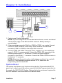
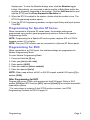
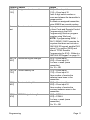
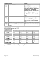
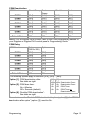
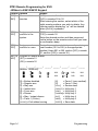
RTX3: Wireless Expansion Module
V2.0
Reference and Installation Manual
Warranty
For complete warranty information, please visit www.paradox.com/terms. Your
use of the Paradox product signifies your acceptance of all warranty terms and
conditions. Imperial, EVO, Spectra SP Series and Esprit are trademarks or
registered trademarks of Paradox Security Systems Ltd. or its affiliates in Canada,
the United States and/or other countries. For the latest product approvals, such as
UL and CE, please visit www.paradox.com. © 2009 Paradox Security Systems
Ltd. All rights reserved. Specifications may change without prior notice.
Patents
One or more of the following US patents may apply: 7046142, 6215399, 6111256,
6104319, 5920259, 5886632, 5721542, 5287111, 5119069, 5077549 and
RE39406 and other pending patents may apply. Canadian and international
patents may also apply.
Table of Contents
Specifications .......................................................................... 4
Hardware Compatibility ........................................................... 4
Overview ................................................................ 5
Description .............................................................................. 5
Features .................................................................................. 5
Installation .............................................................. 7
System Reset ..........................................................................
LED Feedback.........................................................................
All Panels ................................................................................
EVO and SP Series only .........................................................
7
8
8
8
Programming .......................................................... 8
Programming for Imperial ........................................................ 8
Programming for Spectra SP Series ....................................... 9
Programming for EVO ............................................................. 9
After Programming for EVO .................................................... 9
RTX3 Programming Sections for EVO .................................. 10
RTX3 PGM Options for EVO ................................................ 12
RTX3 Remote Programming for EVO
- Without a K641/K641R Keypad .................................... 14
Programming for Esprit and Stand Alone .............................. 15
Esprit Programming............................................................... 15
Stand Alone Use ................................................................... 18
Firmware Upgrade................................................................. 18
Index ....................................................................19
Specifications
Power input voltage:
12Vdc
Frequency:
433MHz or 868MHz
Sensitivity:
-120 dBm
Current consumption:
50 mA
Dimensions
(no antenna):
15cm x 16cm x 3cm (6in x 6.5in x 1.1in)
Operating temperature:
0°C to 49°C (32°F to 120°F)
PGM outputs:
PGM1 and PGM2 - 150mA PGM transistor outputs
PGM3 - form C relay output rated at 5A/28Vdc, N.O./
N.C. (PGM4 optional)
Range:
Refer to the appropriate transmitter Instructions
Other:
Di-pole antenna; Error Correction Algorithm
Approvals:
For the latest information on product approvals, visit
our Web site at paradox.com
Hardware Compatibility
Zones
Remotes
Remote
Type
Wireless
PGMs
Wireless
Keypads
Wireless
Siren
Wireless
Repeater
PX8 Output
Module
Imperial
32
999
REM1
RAC1
REM2
RAC2
REM3
EVO
32
32/96/999
REM1
RAC1
REM2
RAC2
REM3
Spectra SP
32
32
REM1
RAC1
REM2
RAC2
REM3
Esprit
32
REM1
Stand Alone
32
32
REM1
-
8
16
-
-
-
-
8
-
-
-
-
4
-
-
-
-
2
-
-
-
-
-
-
4
Chapter 1: Overview
Description
Features
The RTX3 is a 2-way, 32 zone wireless
expansion module which enables
Imperial, DGP/EVO, Spectra SP
Series or Esprit control panels to
support wireless hardware such as
motion detectors and remote controls.
•
•
Included Items:
• 2 antennas
Required/Optional Items:
• Mounting hardware
• Optional 12Vdc external power
supply (PS27D / PS17)
Compatibility:
• Imperial V32 panels
• EVO / DGP panels
• Spectra SP Series panels
• Esprit panels
•
•
•
•
•
•
•
•
•
•
•
Overview
Up to 32 wireless zones
Support for REM1 / REM2 / REM3 /
RAC1 / RAC2 remote controls
Support for wireless PGMs (EVO /
SP Series only)
Support for all Magellan
transmitters including 2WPGM
Support for two RPT1 and eight
K32RF / K37 (SP Series only)
Support for SR150 Wireless Siren
and RPT1 Wireless Repeater
(SP Series only)
Support for PX8 Output Module
In-field firmware upgradeable
through WinLoad via serial
or 4-wire connection
RF jamming supervision
Low battery, tamper and check-in
supervision
Transmitter signal strength display
3 PGM outputs and 1 optional
output (not available on Imperial
panels)
Noise level test and indicator
Page 5
5
1
6
2
3
7
4
8
9
1. LED display
(see LED Feedback on page 8)
2. Firmware upgrade serial
connection (see Firmware
Upgrade on page 18)
3. Anti-tamper switch
4. PCB screw
5. Antennas
6. Mounting clips
7. Esprit Mode Programming button:
Press to enter programming mode in
Esprit mode (see Programming for
Esprit and Stand Alone on page
page 15). Also used for system reset
(see System Reset on page 7).
8. Connect the Esprit 636/646 LED
keypad to the “Program” connector to
program in Esprit and Stand Alone
mode.
9. Wiring slot
Page 6
Overview
Chapter 2: Installation
3
1
2
1. Control panel Combus connection
NOTE: If you are using the RTX3 as a stand-alone device, connect an external
12Vdc power supply to the RED and BLK terminals. Battery backup is
recommended.
2. If the current draw exceeds 150mA on PGM1 or PGM2, use a relay. Connect
the RTX3’s RED connector to the relay’s RED connector, and the PGM
connector (PGM1 or PGM2) to the relay’s BLK connector.
3. Connect PGM3 and PGM4 to external power supplies if you need additional
power. A PS-817 is recommended. Connect the PGM’s N/O connector to the
external power supply’s “+” connection. Connect the power supply’s “-”
connector to the device’s “-” connector. Connect the PGM’s COM connector to
the device’s “+” connector.
NOTE: Write down the serial number of all wireless modules to be used with
the RTX3. If this installation replaces another RTX3, make sure the
programming can be transferred.
System Reset
The system reset feature only functions during the first 30 seconds after RTX3
power up. In order to reset the system, press and hold the Programming button for
5 seconds, the BUS RX LED flashes. Release the button and press it again while
the LED flashes to reset the module to its default values.
Installation
Page 7
LED Feedback
Legend
R = Red
G = Green
Y = Yellow
= Off
= On
= Flashing
All Panels
ERROR
R Problem with the module
BUS RX
EVO and SP Series only
ERROR
R
Com fail: GRN/YEL
short / no data
R
Com fail: too many
modules / wrong data
BUS RX
BUS TX
G Receiving from panel
BUS TX
G Transmitting to panel
RF RX
G Receiving wireless
RF TX
Y Transmitting wireless
ERROR
BUS RX
BUS TX
G
ERROR
R
Com fail: GRN/
BUS RX G YEL reversed
BUS TX
G
ERROR
R
BUS RX
Combus power
too low
BUS TX
Chapter 3: Programming
This chapter provides programming instructions for Imperial, Spectra SP Series,
EVO, Esprit, and stand alone installations.
Programming for Imperial
When connected to an Imperial panel, all RTX3 settings are programmed using
BabyWare. For more detailed instructions on using BabyWare and programming
remotes, refer to the Imperial System Guide.
To program an RTX3 for an Imperial system:
1. When BabyWare is communicating with the V32 controller and an RTX3
module is connected to the Multibus, it automatically appears in the Modules
Page 8
Programming
display area. To view the Modules display area, click the Modules toggle
button. Alternatively, you may wish to add a module to BabyWare before the
module is physically connected to the system. Click the Add Item button and
add the RTX3 from the Zone Expansion Modules list.
2. When the RTX3 is added to the system, double-click the module’s icon. The
RTX3 Programming window opens.
3. From the RTX3 Programming window, configure Input Setup and Input options.
Click OK.
Programming for Spectra SP Series
When connected to a Spectra SP series panel, the wireless settings are
programmed using control panel programming sections. Refer to the panel’s
Programming Guide.
NOTE: Programming for a Spectra SP series system requires K32 or K10V/H
keypads version 2.0 or higher.
NOTE: Only one RTX3 module can be connected to a Spectra SP Series panel.
Programming for EVO
When connected to an EVO panel, the wireless settings are programmed in
Module Programming Mode.
To enter Module Programming Mode:
1. Press and hold the [0] key.
2. Enter your [INSTALLER CODE].
3. Enter section [4003].
4. Enter the module’s [SERIAL NUMBER]
5. Enter the required [DATA].
NOTE: When used without a K641 or K641R keypad, enable EVO option [1] in
section [3029].
After Programming for EVO
Program the zones, PGMs, and remotes into the EVO panel. Refer to EVO
section [3034] and RTX3 section [001]* options [2] and [3] for wireless transmitter
supervision options.
* For instructions on entering 3-digit RTX3 section numbers, see RTX3
Programming Sections for EVO on page 10.
Programming
Page 9
RTX3 Programming Sections for EVO
Section Feature
[001]
RTX3 options
Option [1] Low battery
supervision
Option [2] Check-in supervision
Option [3] Check-in supervision
time interval
Option [4] RF Jamming
supervision
Option [5] On-board module
tamper supervision
Option [6] PGM1 initial state
Option [7] PGM2 initial state
Option [8] Transmitter tamper
signal
[002]
Details
For RTX3 version 1.5 and higher,
this option is always On
(default: On).
default: Off
Off = 24 hours (default)
On = 80 minutes
default: On
default: Off
Off
On
Off
On
Off
= Normally Open (default)
= Normally Closed
= Normally Open (default)
= Normally Closed
= RTX3 ignores tamper signal
(default)
On = RTX3 reports tamper signal
Remote control options
Option [1] REM2 Visual and
auditory feedback
compatibility options*
Off = Old visual and auditory
feedback (Supported by
REM2 V2.00 or lower)
On = New visual and auditory
feedback (default)
(Requires REM2 V2.01 or
higher with K641 / K641R
keypads)
[030]
View transmitter, remote and PGM To view a transmitter’s 6-digit
serial numbers
serial number, press and hold the
transmitter’s anti-tamper switch.
* The new visual and auditory feedback includes the following system statuses:
stay armed, instant armed and exit delay. Other status feedback has not
changed. Note that for REM2 versions 1.04 or older, stay arm, instant arm and
exit delay statuses are not supported, and a rejection beep will be heard when
the system is in these statuses.
Page 10
Programming
Section Feature
[101] to Assign wireless transmitters
[132]
See
text
Remote controls
[601] to Transmitter signal strength
[632]
[701] to Current battery life
[732]
[801] to Previous battery life
[832]
[671] to 2WPGM signal strength
[678]
Programming
Details
[101] = Zone Input 1
[132] = Zone Input 32
Enter 6-digit serial number or
press and release the transmitter’s
tamper switch.
To delete an assigned transmitter,
enter 000000 as a serial number.
To program remotes controls, refer
to User Code and Remote Control
Programming in the EVO
Programming Guide or program
remotes using WinLoad.
NOTE: If programming REM1 /
RAC1/ REM2 / RAC2 remotes for
a system that does not include a
K641/K641R keypad, enable EVO
option [1] in section [3029] and
refer to “RTX3 Remote
Programming for EVO - Without a
K641/K641R Keypad” on page 14.
[601] = Zone input 1
[632] = Zone input 32
3 or less = weak (move
transmitter)
4 to 10 = OK
[701] = Zone input 1
[732] = Zone input 32
View number of weeks the
batteries have been in the
transmitter.
[801] = Zone input 1
[832] = Zone input 32
View number of weeks the
previous batteries were in the
transmitter.
[671] = PGM 1
[678] = PGM 8
3 or less = weak (move
transmitter)
4 to 10 = OK
Page 11
Section Feature
[901] to Assign 2WPGMs
[908]
Details
[901] = PGM 1
[908] = PGM 8
Enter 6-digit serial number or
press and release the transmitter’s
tamper switch. To delete an
assigned 2WPGM, enter 000000
as a serial number. If a section
between [901] to [904] is empty,
the RTX3 will use the on-board
PGM.
[910] to PGM programming
Program the Two-Way PGM
[989]
activation event, deactivation
event and PGM Delay options.
Refer to RTX3 PGM Options for
EVO.
[991]
View two-way PGM tamper trouble PGM # in trouble will be displayed
[992]
View two-way PGM supervision
PGM # in trouble will be displayed
trouble
RTX3 PGM Options for EVO
PGM Activation
PGM Number
Event Group Feature Group Start #
End #
PGM1
[910]
[911]
[912]
[913]
PGM2
[920]
[921]
[922]
[923]
PGM3
[930]
[931]
[932]
[933]
PGM4
[940]
[941]
[942]
[943]
PGM5
[950]
[951]
[952]
[953]
PGM6
[960]
[961]
[962]
[963]
PGM7
[970]
[971]
[972]
[973]
PGM8
[980]
[981]
[982]
[983]
Default Data
000
000
000
000
NOTE: For a complete list of events, refer to the PGM programming section of
your DGP/EVO control panel’s Programming Guide.
Page 12
Programming
PGM Deactivation
PGM Number
Event Group Feature
Start #
End
Group
PGM1
[914]
[915]
[916]
[917]
PGM2
[924]
[925]
[926]
[927]
PGM3
[934]
[935]
[936]
[937]
PGM4
[944]
[945]
[946]
[947]
PGM5
[954]
[955]
[956]
[957]
PGM6
[964]
[965]
[966]
[967]
PGM7
[974]
[975]
[976]
[977]
PGM8
[984]
[985]
[986]
[987]
Default Data
000
000
000
000
NOTE: For a complete list of events, refer to the PGM programming section of
your Digiplex or Digiplex EVO control panel’s Programming Guide.
PGM Delay
PGM Number
Delay
Options
(000 to 255)
PGM1
[918]
[919]
PGM2
[928]
[929]
PGM3
[938]
[939]
PGM4
[948]
[949]
PGM5
[958]
[959]
PGM6
[968]
[969]
PGM7
[978]
[979]
PGM8
[988]
[989]
Default Data
005
Off
The following options apply to sections [919], [929]... [989]:
Option [1]: PGM deactivation after:
See table on right
Option [2]: PGM base time:
On = Minutes
Off = Seconds (default)
[1]
Off
Off
On
On
[8]
Off
On
Off
On
Deactivation Event
Deactivation Event
PGM Timer
PGM Timer or
Deactivation Event
Option [8]: Flexible PGM deactivation*:
See table on right
* In order to use the “Flexible PGM deactivation” option (option [8]), the “PGM
deactivation after option” (option [1]) must be On.
Programming
Page 13
RTX3 Remote Programming for EVO
- Without a K641/K641R Keypad
Section Feature
Details
[040] to View or delete used [040] = remotes 1 to 8
[043]
remotes
[043] = remotes 25 to 32
After entering the section, select which of the
eight remote positions you wish to delete. Any
remote position displaying “ ” will be deleted
when [ENTER] is pressed.
[201] = remote 01
[201] to Assign remote
[232] = remote 32
[232]
controls to the
Enter the desired section and then press and
system
hold a button on the remote control until you hear
a confirmation beep.
[301] to Assign remotes
Assign the remote controls to users by entering a
[332]
controls to users
user number (001 to 255) in the appropriate
section (Users 001 to 255, section [301] = remote
01, section [332] = remote 32.)
[401] to Program or delete remote
[432]
[401] = remote 01
[432] = remote 32
*
_____ / _____ / _____ / _____ / _____ / _____ / _____ / _____
(default: 15000000)
[0] = Button disabled
[1] = Regular arm
[2] = Stay arm
[3] = Instant arm
[4] = Force arm
[5] = Disarm
[6] = Stay / instant disarm
[7] = Panic 1 (Police)
[CLEAR] = Exit without saving
Page 14
N/A
+
N/A
N/A
N/A
+
N/A
N/A
[8]
= Panic 2 (non-medical)
[9]
= Panic 3 (fire)
[STAY] = Smoke reset
[FORCE] = Utility key 1
[ARM] = Utility key 2
[DISARM]= Utility key 3
[BYP]
= Utility key 4
[MEM] = Utility key 5
[ENTER] = Save data
Programming
Programming for Esprit and Stand Alone
To enter programming mode with Esprit or in Stand Alone mode:
1. Connect an Esprit 636 or 646 to the “Program” connector.
2. Press the “Esprit Mode Programming” button.
3. Press [ENTER] on your Esprit keypad and enter the installer code
(default: 757575).
4. Enter the desired section number.
Esprit Programming
Section Feature
[000]
Installer code
PGM initial state
Option [6] PGM1 initial
state
Option [7] PGM2 initial
state
[101] to Wireless transmitter
[132]
assignment
Details
Set installer code (4 or 6 digits, default:
757575)
[004]
[301] to User code assignment
[332]
[201] to Remote control
[232]
assignment
Programming
Off = Normally open (default)
On = Normally closed
Off = Normally open (default)
On = Normally closed
[101] = Zone input 1
[132] = Zone input 32
Enter 6-digit serial number or press and
release the transmitter’s tamper switch. To
delete an assigned transmitter, enter
000000 as a serial number.
[301] = User 01
[332] = User 32
Assign a valid user code from the Esprit
Panel into the RTX3. To delete a user
code, press [2ND] and then [ENTER].
[201] = Remote control 01
[232] = Remote control 32
Press [ENTER]. After the confirmation beep,
press and hold any button on the remote
until you hear two beeps.
To delete a remote control, press [2ND]
followed by [ENTER].
Page 15
Section Feature
Details
[401] to Remote Control Button Options
[432]
[401] = remote control 01
[432] = remote control 32
Option [1] Option [2] Option [3] Definition*
Off
Off
Off
No Arm or Disarm
On
Off
Off
= Regular Arm
Button
(default)
Off
On
Off
= Regular Arm
Button
On
On
Off
Button
Button
Off
Off
On
Button
On
Off
On
Button
Button
Off
On
On
Button
Button
On
On
On
Button
= Regular Arm
= Regular Arm
= Force Arm
= Force Arm
= Stay Arm
= Regular Arm
= Stay Arm
= Stay Arm
* Buttons used to arm the system are also used to
disarm the system.
Option [4] To select PGM,
see section
[011]
Option [5] To select PGM,
see section
[012]
Option [6] To select PGM,
see section
[013]
Option [7] To select PGM,
see section
[014]
Option [8]
Page 16
Enable button
(default = On)
Enable button
(default = On)
Enable button
(default = On)
Enable button
(default = On)
Enable button
(default = On)
for PGM activation
for PGM activation
for PGM activation
for PGM activation
+
for Panic Alarm
Programming
Section Feature
[011] to PGM output activation
[014]
[011] = Remote Button
[012] = Remote Button
[013] = Remote Button
[014] = Remote Button
Option [1] Activate PGM
1 output
Option [2] Activate PGM
2 output
Option [3] Activate PGM
3 output
Option [4] Activate PGM
4 output
[021] to PGM latch / delay
[024]
[021] = PGM 1
[024] = PGM 4
Option [0] Latched
Option [1] 1 second
Option [2] 5 seconds
Option [3] 10 seconds
Option [4] 20 seconds
Option [5] 40 seconds
Option [6] 60 seconds
Option [7] 2 minutes
Option [8] 4 minutes
[001]
Code length
Option [1] Code length
Option [2]
Programming
Panic alarm
Details
Refer to section [401] to [432]
Default On in section [011]
Default On in section [012]
Default On in section [013]
Default On in section [014]
(default)
On = 6-digit access code length (default)
Off = 4-digit access code length
On = Panic alarm toggles PGM and panic
alarm (default)
Off = Panic alarm toggles the PGM
Page 17
Section Feature
[002]
PGM output on panic
Option [0] No PGM output on panic alarm
Option [1] Toggle PGM 1 on panic alarm
Option [2] Toggle PGM 2 on panic alarm
Option [3] Toggle PGM 3 on panic alarm
Option [4] Toggle PGM 4 on panic alarm
[003]
RF lockout on panic
Option [0] No RF signal lockout on panic alarm
Option [1] 30-second RF signal lockout on panic alarm
Option [2] 60-second RF signal lockout on panic alarm
Option [3] 90-second RF signal lockout on panic alarm
Option [4] 120-second RF signal lockout on panic alarm
Details
(default)
(default)
Stand Alone Use
The RTX3 can be used as a Stand Alone module. The programming sections are
the same as when used with an Esprit with the following exceptions:
•
In Stand Alone mode, section [001], option [1] and option [2] will not affect
system use.
• Panic alarms can only be used to toggle PGMs on the RTX3 in Stand Alone
mode.
• Sections [301] to [332] do not have to be programmed.
NOTE: To program wireless transmitters in Stand Alone mode, you must use a
PX8 in conjunction with the RTX3. Refer to the PX8 Instructions for more
information.
Firmware Upgrade
The RTX3 firmware can be upgraded using either a serial connection or a fourwire connection. For firmware upgrade instructions, refer to the Firmware
Upgrade Instructions document which is available at paradox.com > Software >
WinLoad. To upgrade an RTX3 on an Imperial system, refer to the RTX3 chapter
in the Imperial System Guide.
Page 18
Programming
Index
Numerics
2WPGM
Assigning ................................................................................ 12
Signal strength ........................................................................ 11
A
Antennas .......................................................................................... 6
Anti-tamper switch ........................................................................... 6
Assign wireless transmitters .......................................................... 11
B
Battery life ...................................................................................... 11
C
Check-in supervision ...................................................................... 10
Check-in supervision time interval ................................................. 10
Code length ................................................................................... 17
Compatibility .................................................................................... 4
Consumption .................................................................................... 4
Current battery life ......................................................................... 11
Current consumption ........................................................................ 4
D
Dimensions ...................................................................................... 4
E
Esprit .............................................................................................. 15
Esprit mode ...................................................................................... 6
EVO ................................................................................................. 9
F
Firmware upgrade .......................................................................... 18
Frequency ........................................................................................ 4
I
Imperial ............................................................................................ 8
Input voltage .................................................................................... 4
Installation ........................................................................................ 7
Page 19
Installer code ................................................................................. 15
K
K641 ................................................................................................ 9
L
LED display ...................................................................................... 6
LED feedback .............................................................................. 6, 8
Low battery supervision ................................................................. 10
M
Module programming mode (EVO) .................................................. 9
Mounting clips .................................................................................. 6
O
On-board module tamper supervision ............................................ 10
Operating temperature ..................................................................... 4
P
Panic alarm .................................................................................... 17
Patents ............................................................................................. 2
PGM
Activation ................................................................................ 12
Deactivation ............................................................................ 13
Delay ...................................................................................... 13
initial state ......................................................................... 10, 15
Latch / delay ........................................................................... 17
Options for EVO ..................................................................... 12
Output activation ..................................................................... 17
output on panic ....................................................................... 18
outputs ...................................................................................... 4
Programming .......................................................................... 12
Supervision trouble ................................................................. 12
Tamper trouble ....................................................................... 12
Power input voltage ......................................................................... 4
Previous battery life ....................................................................... 11
Programming ................................................................................... 8
Programming button ........................................................................ 6
Page 20
R
REM2 visual and auditory feedback .............................................. 10
Remote control assignment ........................................................... 15
Remote control button options ....................................................... 16
Remote controls ............................................................................. 11
Reset ............................................................................................... 7
RF Jamming supervision ............................................................... 10
RF lockout on panic ....................................................................... 18
S
Sensitivity ......................................................................................... 4
Signal strength ............................................................................... 11
Specifications ................................................................................... 4
Spectra SP series ............................................................................ 9
Stand alone .............................................................................. 15, 18
System reset .................................................................................... 7
T
Temperature .................................................................................... 4
Transmitter signal strength ............................................................ 11
Transmitter tamper signal .............................................................. 10
U
User code assignment ................................................................... 15
V
View serial numbers ....................................................................... 10
Voltage ............................................................................................. 4
W
Warranty .......................................................................................... 2
Wireless transmitter assignment .................................................... 15
Wireless transmitter supervision options ......................................... 9
Wiring slot ........................................................................................ 6
Page 21
For technical support in Canada or the U.S., call 1-800-791-1919,
Monday to Friday from 8:00 a.m. to 8:00 p.m. EST. For technical support
outside Canada and the U.S., call 00-1-450-491-7444, Monday to Friday
from 8:00 a.m. to 8:00 p.m. EST.
Please feel free to visit our website at www.paradox.com.
RTX3-EI09 07/2009
PARADOX.COM
Printed in Canada