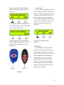
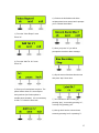
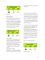
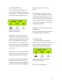
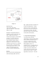
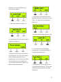
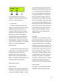
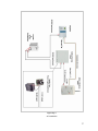
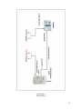
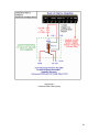
1
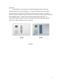
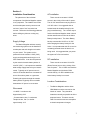
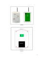
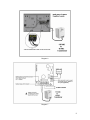
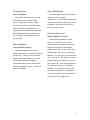
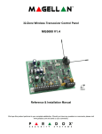
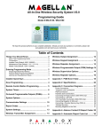
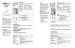
Installation Manual Marine Magellan 6130/6160 Table of Content Introduction……………………………….....2 DCTXP2…………………..…….……...20 Section 1: Installation Consideration…...2 PMD-75 Motion Detector……………...22 Supply Voltage Considerations...........................2 SD-738 Smoke Detector………………23 Location Considerations…….…………...............3 Battery Low Voltage Detector………...23 Section 2: Mounting………………………..4 High Water Alarm……………………...25 Marine Magellan……………………………..........4 Artion GSM Module…………………....................5 Artion Battery Backup...…………………………...5 Section 3: Electrical Installation…………7 AC Installations………………….…………………7 DC Installations……………...………………….....9 Internal Battery Backup / Marine Magellan…......9 Communication Lines…………………..….…..….9 Section 4: Programming…………………...12 1 – Language……………………………………..12 2 - User Profile……………………………………12 3 – Communicator………………………………..14 4 – Delays and Tones……………………………17 5 – System Test…………………………………..17 6 - Zone Profile: Overview…………………..…..18 Zone Definitions………………………..18 6 - Zone Profile: Programming…………...……..25 7 – Output Profile: Overview…………………….27 PGM Activation Events ……………….27 PGM Electrical Installation……………29 7 – Output Profile: Programming……………….29 8 – Keypad Profile Overview………………..…..31 8 - Keypad Profile Programming……….……....33 9 – Repeater Profile Overview………...………..33 9 - Repeater Profile Programming……..……….33 10 – Signal Strength………………………..........34 11 – Passwords…………………………..……....34 Console Trouble…………………………..……...35 AC Diagram……………………………………….37 DC Diagram……………………………………….38 PGM Wiring Examples………………………39 -42 Programming web…………………………...…...43 Marine Magellan Keypad Description…….…......4 Zone Hardware Descriptions…………20 1 Introduction Congratulations on your purchase of the Marine Magellan wireless security and monitoring system for your yacht (Diagram 1). The system is designed to provide reliable protection giving you true piece of mind when you are away from your vessel. This guide is designed to walk the installer through the complete setup and basic wireless programming of the Marine Magellan System. Please read the manual thoroughly before beginning. It is recommended that the installer have a basic understanding of electrical fundamentals and adheres to the ABYC standards of marine electronics. Diagram 1 2 Section 1: Installation Consideration AC installation The placement of the individual There must be a constant 110 VAC components of the Marine Magellan system source in the vicinity of the units for power. is very important. The installer must make The 16 VAC transformer must plug into the sure that adequate security concerns and 110 VAC outlet. It is suggested that an end user “ease of use” are taken into isolated outlet be installed strictly for the account. Reference the following guidelines plug in transformer(s). The 16 VAC output before drilling any holes or running any feeds to the Marine Magellan head unit and wires. another transformer can feed to the Artion Battery backup board. The Artion Battery Supply Voltage The Marine Magellan wireless security backup converts this 16 VAC to 12 VDC while charging the battery backup for the and monitoring system must be installed in Artion. It is important that this AC source be an adequate and well thought out location constantly powered when the boat is not on your vessel. The system can be being used. It is suggested that you power powered from the vessels 110 AC (VAC) the system off of its own breaker. supply and stepped down through our 16 VAC transformers. It can also be powered DC installation by the vessels domestic battery banks 12 There must be a constant 12 Volt DC volts DC (VDC). It is important to establish (Direct Current) source in the vicinity of the what voltage supply best suits your vessels units for power. This 12 VDC must feed the needs. Typically an AC power source is Marine Magellan and the Artion GSM used on all vessels that have a constant AC module directly. On DC installations the source from shore power or a generator. Artion battery backup is not used. Powering the system through the vessels battery banks is typically done on smaller Location Considerations boats where AC power is not constant The Marine Magellan and the Artion Wire needs GSM Module must be mounted on the -18 AWG / 2 conductor wire interior of vessel. They should be Approximately 20 ft. located as centrally as possible to all the - Communication wire / 2 conductors proposed zones. This area must be Telephone wire, Cat 5, or similar clear from moisture and not susceptible approximately 12 ft. to drastic temperature changes. 3 There must be an adequate wire run Applicable) according to the criteria on the behind the Marine Magellan, Artion, and previous pages, it is time to mount them. the Artion Battery Backup Case (if Marine Magellan applicable) so wiring is not exposed. The Marine Magellan uses a plastic wall Exposed wires compromise the systems plate for wall mounting (Diagram 2). If security as intruders could cut essential mounting the unit on the wall you must first communication lines. The installer must pop out the rectangular cutout labeled D on properly research the proposed the plate to allow wiring access. locations of the devices so they have a clear unobstructed wire run. The Marine Magellan head unit and Artion unit should be powered up and communicating with no wire susceptible to tampering. The Artion should be as high as possible on your vessel, mounted above the water line for best cellular Diagram 2 communication, and located within 12 ft of the Marine Magellan head unit. Use the included 3 ft. extension cable to extend the antenna and assist with the clarity of the call. The Marine Magellan can be mounted on a wall by first securing the wall plate to the wall and then mounting the console on the secured wall plate. 1.) Place the wall plate on the desired spot It is important that the Artion be accessible but not visible. This is because in the event of an alarm, you do not want the communication tool exposed to any thieves. Possible places include inside cabinets or behind removable panels. of the wall. 2.) Drill and insert screws into holes labeled A as shown Diagram 2 3.) With the Rectangular cutout D removed you must now drill a 5/8 inch hole into the wall as to allow for wiring access from the rear of the Marine Magellan. Section 2: Mounting Once you have found an adequate location for the Marine Magellan, Artion, and the Artion Battery Backup Case (if 4 plate. This will secure the console to the wall. Artion GSM Module It is important that the GSM communication module be mounted in such a location to allow accessibility without obvious visibility. Follow the steps below. 1.) Establish a proper location 2.) Mark the necessary holes to mount the Artion and allow wiring access. 3.) Drill the mounting holes 4.) Drill the 5/8 wiring access hole 5.) Screw in the top two screws on the left and right side of the area. Leave approximately 1/8 inch between the wall and the underside of the screw head. 6.) Feed your power, trigger and communication wires through the wiring Diagram 3 hole. 7.) Place the GSM cellular module onto 3. Place the console back plate flush against the mounted wall plate as shown in Diagram 3. 4. Slide the Marine Magellan’s open slots labeled F (Diagram 3) onto the wall plate’s tabs labeled B. 5. Gently apply downward pressure to insert the wall plates tabs into Marine Magellan’s open slots. the top two screws matching up the respective holes and push downwards to lock the unit into place. 8.) Depress the two tabs at the base of the GSM cellular module and remove the top Cover. 9.) Screw the final two screws on the bottom of the GSM cellular module. 10.) Place cover back on Artion. 6. Once the Marine Magellan’s power and communication wires are hooked up Artion Battery Backup (Electrical Installation, Page 8), Insert two This case should be mounted in the vicinity screws through the wall plate’s screw holes of the Artion. There are four screw holes labeled C and into holes labeled E ( inside the metal case at all corners Diagram 3 ) in the Marine Magellan back (Diagram 5). 5 Diagram 4 Diagram 5 6 Section 3: Electrical Installation * Power should be denied when making all electrical connections. Only apply power when all wire connections have been doubled checked for proper setup. This section closely describes how to power the essential components of the system for both AC and DC installations. It also shows how to hook up the Ring and Tip communication wires between the Marine Magellan Head unit and the Artion GSM module. A basic final wiring setup for the typical AC and DC installations can be into an existing outlet to get power, make sure that the existing breaker is properly current rated for the additional outlet. In either case, the AC breaker must be left on while away from boat. Connect the two conductor wire to the “AC” inputs of the Marine Magellan. On the other end, connect the two wires to the output screw terminals on the AC transformer (Diagram 6). It is suggested that you crimp on spade connectors to the wire for a secure connection to the transformer. Since the voltage source is AC, the two connections are interchangeable between the two inputs. referenced on Appendage 1 and Appendage 2 respectively. AC power setup Marine Magellan The AC plug in transformer supplies Battery Backup The external battery backup case has been designed to supply a constant 12 VDC to the Artion GSM module. It simply takes the 16 VAC input from the transformer, voltage to both the Marine Magellan inverts it to 12 VDC, and charges the Console and the battery backup supply. backup battery (Diagram 7). This device is The 110 VAC supply to the outlet should be only used during AC installations. on its own breaker. If the installer must tap 7 Diagram 6 Diagram 7 8 DC power Setup Marine Magellan The Marine Magellan panel can easily Artion GSM Module The Artion GSM module simply needs a constant 12 VDC to operate be powered from the vessels 12VDC (Diagram 10). In AC installations this power system. Simply get a constant voltage comes from the battery backup case. In DC source to the unit from the vessels battery installations, this power comes from the banks or domestic bus (Diagram 8). It is primary domestic source. suggested that the installer fuse protect the Marine Magellan system by placing an in- Communication Lines line 1 amp fuse on the Positive input wire Marine Magellan to Artion (not supplied). With the power establish for all the devices, it is now time to hook up the Marine Magellan communication wire between the Marine Internal Battery Backup Magellan and the Artion GSM Module. The Marine Magellan uses its own Simply connect the “Line Out” of the Artion backup battery pack to provide power during GSM module to the “Line In” of the Marine a power loss. This is not to be confused Magellan. The “Line Out” of the Artion has a with the Artion Battery Backup. A 7.2Vdc tip “T” and ring “R”. The general rule when 1.8Ah NiMH (Nickel Metal Hydride) hooking up this line is red goes to ring and rechargeable battery pack is included with green goes to tip. There are two options for the Marine Magellan console. Connect as connecting to the “Line in” of the Marine shown in Diagram 9. Magellan. The first option is a line plug in connection through an RJ-11 (Diagram 11). The second option is a direct connection to the “Ring” and “Tip” (Diagram 12). 9 Diagram 8 Diagram 9 10 Diagram 10 Diagram 11 Diagram 12 11 Section 4: Programming With the Marine Magellan and Artion GSM module now powered up and communicating with each other, it is time to program the different areas of the system. 1 - Language The Marine Magellan system is Upon initial startup of system, you are available in a variety of different languages. brought to the “System Setup” menu. As French and English are preloaded, to add you go through this programming guide, you additional languages you will need to will see screen shots of the Marine upgrade the firmware. This is a very simple Magellan. The complete layout of the process that will require the use of the programming menus can be referenced on Paradox UIP-256 and a laptop computer. Appendage 7. The installer may wish to Contact Paradox Marine for language install the zones (wireless sensors) and upgrades on your panel. PGMS (relays) before programming (See 6 – Zone Profile and 7 –Output Profile) Note that the black shaded buttons represent the button that you need to press. When navigating through the different menus, press the center key to go to the “next” screen. To access the “System Setup” menu: Select the desired language by pressing the appropriate number on the main keypad 2 - User Profile You can program up to sixteen different users on your Marine Magellan panel. For 1.) Press “menu” from the main screen security reasons, once you change the master code (User 1) from the default “1234” you will be prompted to enter the master code every time that you enter the system setup menu. A User is defined as a person with access to the system via a pass code 2.) Press “ok” and ‘next’ to navigate and/or key fob remote. Common examples menu of the Master, user 2, and user 3 are the owner, captain, and first mate respectively. Every user can have only one remote each 12 for a total 16 maximum remotes on the system. In this section you have the ability to change user passwords, user voice labels, and add/delete remotes. System Master Code With the System Master code a user can use any arming method and can program any user’s (from 1 to 16) access Code. The System Master is four digits (default), where 2. Select which user you wish to add/modify by pressing “next”. When the desired user appears, press “ok” and follow the menus to set: each digit can be any number from 0 to 9. (Default: 1234) User Codes A person must be assigned to a user code in order to have access to the Marine Magellan. A user code defines the extent of a user’s access to the system and consists 3.) Enter your new user code of a code # (PIN) and user options. The Marine Magellan supports one System Master code and 15 User codes. 4.) Confirm the code to assure proper entry. 1. From the “User Profile” menu, press “ok”. 5.) Once you press “yes” you will be prompted to record a user label. The user 13 label is the person who will be using that password. (Examples: captain, first mate, owner, etc.) 3 – Communicator In this section you will assign the various call-out telephone numbers for the various recipients. Upon receiving the call, the user will hear the prerecorded voice label of the boat name and the condition that exists. Since the Marine Magellan system sends its alarm and event notifications directly to the end user, no central reporting setup is 6.) To program a remote to that user press necessary. “yes” otherwise press “no”. Only one remote can be programmed per user. 7.) When prompted to “Press any button on From the “Communicator” menu Remote”, depress any button for 1 second Press “ok”. on your REM1 or REM2 remote control Voice Report (Diagram 13). The voice report can send out alarm events to up to five different numbers. By default whenever an alarm occurs on the vessel, the first number will receive a call. If that recipient does not acknowledge the alarm or disarm the system, the call will disconnect and move on to the second number. This process continues in this fashion through to fifth recipient and then begins the cycle again two more times To add recipients, see below: REM 1 REM 2 Diagram 13 14 4.) Continue in this fashion until all the recipients have been entered and it prompts you to “Record Alarm Mes?” 1.) From the “Voice Report” menu Press “ok”. 5.) Once you press “ok” you will be prompted to record an alarm message 2.) From the “Add Tel. # 1” menu Press “ok”. 6.) Say the name of the boat after the tone and press “stop” when done. 3.) Enter your first telephone recipient. The pause feature allows a 1 second space during callouts (for Charles phone or satellite phone headers). It is not necessary to dial a “1” before the area code. 7.) You can listen to the recording by pressing “play”, re-record by pressing “no”, or accept it by pressing “yes” 8.) Now go back into the communicator screen by pressing “next” or pressing “3”. 15 disarms your system thus informing you that he is aboard. 9.) From the “Communicator” menu Press “ok”. System troubles: Use this report type to have the Marine Magellan console call you when specific troubles occur. After entering Utility Reporting the menu, select the desired trouble(s) you Utility reporting is an option that sends out a wish to be notified about. This feature can pre-recorded message for specific utility be used to inform you of a power failure on events on your panel to any two designated your vessel and internal battery failure of the numbers. The Utility reporting programs the Marine Magellan panel. same method as “Voice Reporting” (See Above). The three specific events that can • Zone activation: When a specified zone is be set up are below. Only one of these breached or opened, the Marine Magellan events will work at one time. console will call one or both of the programmed telephone numbers. After entering this menu, select the desired zones you wish affected. Use this feature to be informed when a specific zone is breached. For example, if you have a safe on your vessel, you can have the Marine Magellan call you whenever the safe is opened or Report Types breached. • Disarm with user: Use this report type to program the Magellan console to call you Select “ok” and chose the specific when specific users disarm the system. After entering the menu, select the desired user(s) that you wish reported. This feature is useful when you wish to know when specific people disarm the system. For example, you can program the Marine type of utility report you want the Magellan to call you whenever your captain recipient to receive. 16 4 – Delays and Tones all zones (except 24 Hr zones) in the This menu allows you to set entry / exit system. times as well as associated sounds for the Marine Magellan. Below are the definitions of the different functions within this menu. Bell Cutoff Delay – This is the amount of time that the Marine Magellan will sound its internal sirens during an alarm event. The system will stay in alarm after this time is up. However the Bell cutoff delay will reinitialize if a zone is opened again. The default bell cut-off delay is 4 minutes. Bell Squawk – This feature enables the siren Select “ok” to go into the to squawk once Delays and Tones menu upon arming with a remote control and twice upon disarming with a remote control. Entry Delay 1 – The entry delay 1 is the amount of time that the user has to disarm the Marine Magellan system from an armed state. It is engaged whenever a “delay 1” 5 – System Test This feature allows you to test all the zone is opened (see 6 - zone profile). By different functions of the system to check for default it is 45 seconds. After the time delay proper operation. Simply select the entity screen you can change the entry tone that that you wish to check (zones, outputs, you will hear. Entry Delay 2 – This entry delay is identical to the first except it is engaged whenever a delay 2 zone opens (see 6 - zone profile). remotes, etc) and trigger them. The Marine Exit Delay – The Exit Delay determines the Magellan will announce the event and amount of time a user has to leave the confirm proper operation. protected area before the Marine Magellan arms the system. The Exit Delay applies to Press “ok” to begin system test 17 6 - Zone Profile Entry Delay 1 Description Typical position: Primary entry Zones are defined as the assorted When the system is armed and a zone wireless sensors that transmit open/close defined with Entry Delay 1 opens, the conditions to the Marine Magellan. This console will generate an alarm after the section describes how to program the programmed Entry Delay 1 timer elapses. various zones. These zones come in the This is to provide users with enough time to form of door contacts, motion detectors, enter the protected area and disarm the smoke detectors, high water alarms, and low system. Entry Delay zones are commonly voltage detectors to name the most used at the entry/exit points of the boat. common. The Marine Magellan system can Using different Entry Delays (see Entry hold up to 32 of these zones. Whenever Delay 2 below) is useful when, for example, any of these zones batteries start getting one entry point requires a longer delay than low, the Marine Magellan will be alerted and another entry point. display an information key on the screen (See Appendage 4). Essentially, the Entry Delay 2 installer must get into the “add zone x” (x = Typical Position: Secondary Entry Door 1-32). Once “ok” is pressed for the zone Contacts that you are adding, it will prompt you to “Press tamper or Press Learn Btn.” Learn Mode allows Marine Magellan to This zone is identical to the Entry Delay 1 zones, except it uses a separate Entry Delay Timer. look for an open wireless signal from a zone and place it into a designated position in the Follow Zones console. Before you “learn” the assorted Typical Position: Interior Motion Detectors zones into your Marine Magellan Panel, it is When an armed Follow zone opens, the important to understand the fundamentals of console will immediately generate an alarm the most commonly used zone definitions unless an Entry Delay zone opens first as and programming techniques. described in the situations below: Zone Definitions • If an armed Follow zone opens after an A zone definition is the type of reaction the installer wants when that zone gets breached. There are assortments of Entry Delay zone opens, the console waits until the Entry Delay Timer has elapsed before generating an alarm. definitions that can associate with a zone. The most common definitions are outlined • If an armed Follow zone opens after more below: than one Entry 18 Delay zone opens, the console will wait until • All zones defined as Instant/Stay zones the Entry Delay become Instant Timer of the zone that opened first has zones when the Marine Magellan system is elapsed. This feature is commonly used Regular armed. when a motion detector is protecting the • All zones defined as Instant/Stay zones area occupied by the entry point keypad. become Stay zones This will prevent the motion detector from when the Marine Magellan system is Stay or causing an alarm when a user Instant armed. enters through the entry point to disarm the system. Delayed Fire Zones Typical Position: Smoke Detectors Follow/Stay Zones Typical Position: Interior Motion Detectors Follow/Stay zones function as follows: When a Delayed 24Hr. Fire zone opens, whether it is armed or disarmed, the console will react. Delayed • All zones defined as Follow/Stay zones 24Hr. Fire zones are commonly used in become Follow galleys where a smoke detector often zones when the Marine Magellan system is generates false alarms (i.e., burning bread, Regular armed. etc.). • All zones defined as Follow/Stay zones become Stay zones 24Hr. Buzzer Zones when the Marine Magellan system is Stay or Typical Position: High Water and Low Instant armed. Battery Voltage zones This zone definition is used in cases where Instant Zones you want an alarm notification whether the Typical Position: Door contacts on Hatches system is armed or disarmed. When an armed Instant zone opens, the • Whenever a 24Hr. Buzzer zone opens, console immediately whether the console generates an alarm. Instant zones are is armed or disarmed, the console sets off commonly used for the keypad’s windows, patio doors, skylights and other buzzer to indicate that the zone was perimeter type zones. breached. • The console will report the alarm, but will Instant/Stay Zones not enable the bell/ Typical Position: Door contacts on Hatches siren output. The Instant/Stay zones function as follows: • Enter any valid Access code on the keypad to stop the buzzer. 19 Zone Hardware Descriptions Power: 2 x “AAA” This section loosely describes the basic Description: This device can be installed in operation of the assorted zones for the another fashion utilizing is its universal system. For more specific data on the inputs. These two input terminals accept a individual sensors please reference the variety of different sensing applications. The guides included in the box of each particular purpose of this option is for secondary sensor. sensor inputs. The most common examples of this application are the High Water, Low Voltage Sensors, and recessed door magnet DCTXP2 sensors. The DCTXP2 Universal input “Magnet Reed Switch” Typical Position: Entry Doors and Hatches Typical Zone Definition: simply needs to see a open/close state change. Open the cover of the DCTXP2 and reference Diagram 15. Delay or Instant Power: 2 x “AAA” Description: This device detects open/close states thru an on board magnet switch. The fixed door contact must be located in a position where the moving magnet comes within ½ inch of the magnet reed switch when the door opens and closes. The magnet reed switch is marked by the triangle on the upper right side of the door contact casing (Diagram 14 and 15). Powering the Unit Verify proper polarity and insert two alkaline “AAA” batteries. After inserting batteries, a power up sequence will begin (10-20 seconds) during which the door contact will not detect an open zone or tamper. Low Battery The door contact performs a battery test every 12 hours. If the voltage is below 2.3V after four consecutive battery tests (48 hrs.), DCTXP2 the red LED will flash at 5 second intervals “Universal Transmitter Input” Typical Position: Any location where and the MG-DCTXP2 will transmit a low battery signal secondary sensing applications are needed. Typical Zone Definition: Delay or Instant Diagram 14 20 Jumpers Normally Open Reed Switch/Universal Input: open = “zone open” signal closed = “zone closed” signal JP1 ON Normally Closed Reed Switch/Universal Input: open = “zone closed” signal closed = “zone open” signal JP1 OFF JP2 Diagram 15 Mounting Not Used Table 1 Learn Mode It is suggested that you first apply the Learn Mode allows you to transmit the door contact and magnet with double sided serial numbers of each input to your Marine tape and test it before permanently Magellan console wirelessly. To enter Learn mounting the unit. Once you have mounted Mode, open the cover and wait until the LED it and put your batteries in, programmed and stops flashing. There are two methods to tested for operation, you then can then pre- program the DCTXP2 depending on whether drill and screw in you door contacts. the “Magnet Reed Switch” or the “Universal Transmitter Input” is being utilized (Table 2). Jumpers You will notice a jumper at “JP1”. With Make sure that the Marine Magellan is in the proper programming screen and says “Press the jumper “on” the contact will reed open to Tamper or Press Learn Btn” (6 – Zone the Marine Magellan panel when the magnet Profile, Programming). Essentially, if you is not present. With the jumper “off” the are using the “Magnet Reed switch”, contact will reed closed to the Marine momentarily Magellan panel when the magnet is not press the red tamper switch once in one present (Table 1). This comes in handy with second. If you are programming specific sensing applications that may have the “Universal Transmitter Input”, simply opposite normal states. momentarily press the red tamper button twice in one second. 21 Diagram 16 PMD-75 Motion Detector 2. Insert the battery holder into the back Typical Position: Salon, Stateroom, and cover and affix the battery connector to the Hallway PCB (see “A1” and “A2” in Figure Typical Zone Definition: Follow or Follow / Mounting Stay It is recommended that the motion detector Power: 3 x “AAA” be mounted high up on the wall or corner of Description: It is recommended that the your vessels interior. It should focus on motion detector be mounted high up on the susceptible areas that could be prone to wall or corner of your vessels interior. It break in. It is important not to focus on areas should focus on susceptible areas that could that could cause false alarms (i.e. focusing be prone to break in. It is important not to in areas that may have movement thru focus on areas that could cause false alarms glass). Temporarily mount the detector with (i.e. focusing in areas that may have double sided tape and test that the location movement thru glass). is adequate with no possible false alarms. Powering the Unit 1. Insert 3 “AAA” batteries into the battery Walk Test holder while verifying polarity (Diagram 16). Open the cover in order to trigger the antitamper switch, and then snap the cover back 22 into position. This will activate the motion Powering the Unit detector’s walk-test mode for 3 minutes. Open up the back cover of the unit to access the 9 volt battery. There is a plastic wrap Learn Mode around the battery that needs to be Power up the unit and allow the LED to removed. Snap in the battery, place it in the cycle out with the cover open. Make sure compartment, close the cover, and secure it that the Marine Magellan is in the proper with the included screw. programming screen and says “Press Replacing the Batteries Tamper or Press Learn Btn” (6 – Zone When the Battery starts to fade out, the Profile, Programming). Press the tamper device will generate an alarm every 15 switch on the board once briefly (Diagram minutes to alert you of it. 17 reference “B”). Mounting Place the mounting plate in the designated SD-738 Smoke Detector Typical Position: Galleys, salons, and electrical closets location. Pre-drill and secure the plate. Place the detector onto the plate, match up the key, and turn clockwise until it stops. Typical Zone Definition: Delay Fire Power: 9V Battery Learn Mode With the unit powered up, make sure that Description: This device has a highsensitivity photoelectric smoke sensor with its own built-in siren (Diagram 17). the Marine Magellan is in the proper programming screen and says “Press Tamper or Press Learn Btn” (6 – Zone Profile), Programming). Hold down the test button on the top of the smoke detector for approximately three seconds. Battery Low Voltage Detector Typical Position: Domestic battery Banks Typical Zone Definition: 24Hour/Buzzer Power: 2 x “AAA” Description: The Battery Low Voltage detector is designed to monitor vessels battery bank(s) for low voltage. The voltage detector opens the zone when the battery Diagram 17 voltage drops below 11.6 for a 12 VDC bank or 23.2 for a 24 VDC bank for a period of 23 more than 2 minutes. The Low voltage It is important that the battery bank that you sensor is mounted in a sealed, waterproof, are monitoring is the same one that powers plastic enclosure. Typically it is hooked up your bilge pumps. This is the most vital to the primary domestic battery bank for the bank to monitor when away from your boat. boat. This is because this is the battery(s) Select the voltage you are monitoring on the that powers the bilge pumps and therefore is Low voltage sensor by flipping the switch the most important. between 12 or 24 (Diagram 18 and 19). Once the proper battery voltage is Powering the Unit selected you are now ready to hook up the Unscrew the four screws holding the cover wires. You can hook up directly to the on and open it up. Inside you will see the Ground and negative of the batteries or to a low voltage sensor attached to a DCTXP2. primary bus feed off of it. See Diagram 18 Place the batteries in the DCTXP2. Now you and 19 for 12 VDC and 24 VDC diagrams must program the DCTXP2 to a zone respectively. Once this is accomplished, a location of the Marine Magellan (see green light will light up on the low voltage DCTXP2, “Universal Transmitter Input” ) detector in the case. Secure the case in an unobtrusive location by screwing through the Electrical Connection base of the case. Place the cover back on. With the wireless zone powered up and programmed, you now must connect the respective wires to the battery bank that you wish to monitor (Diagram 18 and 19). Diagram 18 Diagram 19 24 Diagram 20 bilge. Typically the switch is mounted 6 to 8 High Water Alarm inches from the bilge bottom. The best Typical Position: Bilge Areas reference to mount it is about a half inch Typical Zone Definition: 24 Hour Buzzer below the level of the boat manufacturers Power: 2 x “AAA” existing high water switch. The sealed plastic box housing the DCTXP2 should be Description: The High Water detector is mounted above the float switch. designed to monitor the water level in your bilge. The High water float switch is mounted on the stringers in various areas of your bilge. The switch is wired to the DCTXP2 wireless sensor located in a sealed, waterproof, plastic enclosure (Diagram 20). Unscrew the four screws holding the cover and open it up. Inside you will see a DCTXP2. Power the DCTXP2 and then program the DCTXP2 to a zone location of the Marine Magellan (see DCTXP2, “Universal Transmitter Input” ) 6 - Zone Profile Programming You should now have a general understanding of using the wireless sensors and the definitions associated with them. It is now time to program these sensors individually to each zone location of the Marine Magellan console. For organizational sake, it is suggested that you keep like sensors grouped together. For example, if you have five different door contact zones and two High water zones, allocate the doors to zones 1 -5 and the Mounting High Waters to zone 6 and 7. This action Now you must mount the plastic high water alarm and 90 degree plastic shelf in the 25 just makes more sense that having the zones randomly placed. . 4.) This is where you say the name of the particular zone that you just learned into the panel. (ex. Saloon door, Forward High Water, etc.) 1.) Select Zone Profile by pressing “ok” 5.) Vocalize the zone label and press “stop” 2.) Choose which Zone # you wish to add by pressing “next” and “ok”. 6.) You can listen to the recording by pressing “play”, re-record by pressing “no”, or accept it by pressing “yes” 3.) When the screen says “Press Tamper or Press Learn Btn”. Press the “learn” button on the individual sensor that you are programming. For instructions on the where the learn button is on the transmitter see “Zone Hardware Descriptions” under “Learn Mode” for that particular sensor. 7.) Declare the type of zone that you want by pressing next and then ok. For the most common zone type definitions, see (Zone Definitions). 26 can have the PGM toggle on and off from this button or even have timing cycle of 1, 5, 15, or 30 Seconds/minutes. This event is also a secondary toggle on/off option with every single PGM event. This comes in 8.) To add another zone to the next handy if you want to be able to have the available location and repeat the process cockpit lights “Pulse on Alarm” and still be press “yes”, otherwise press “no”. able to turn the lights on through the remote as a convenience when boarding the boat. 7 – Output Profile A PGM is a programmable relay that Before programming the PGM to activate on a button, at least one key fob remote must toggles to its opposite state when a specific be programmed to the system (see User event has occurred in the system. For Profile). Common examples of remote example, a PGM can be used to activate triggered devices are cockpit lights and external sirens or strobe lights, turn on ice underwater lights. makers and much more. The Magellan console includes two onboard PGMs. The Follow bell 2WPGMS communicate wirelessly to the Description: This event allows the PGM to Marine Magellan. The system can support activate following the Bell cut-off delay. The up to a total of four PGMs (e.g., two onboard bell cut-off delay is the amount of time that PGMs + two wireless PGMs OR four the internal 90 decibel siren of the Marine wireless PGMs). Magellan will sound before shutting off. The event scares away would be thieves while All PGMs must be programmed to follow shutting off after a period of time as to not a certain event. This could be as simple as annoy your fellow dock mates. The unit pulsing a light on and off in alarm to stays in alarm and will re-initialize if a zone following a zone opening and closing. is breached again. By default, the bell cut- Before hooking up and programming the off delay is four minutes. To change this PGM, it is important to understand the most time (See 4 – Delays and tones). Common common activation event definitions. examples of bell triggered devices are external audible sirens and spreader lights. PGM Activation Events Alarm activation Remote Access Description: This event allows the PGM to Description: This event allows the PGM to activate upon alarm in a variety of ways. activate from a remote control button on the key fob remote (REM1 or REM2). The user 27 Follow Alarm this are interior lights that may come on Description: The PGM will activate for the when a certain door zone opens up. entire duration while in alarm. The only way to deactivate the PGM is by disarming the Follow arm system via key pad, key Description: The PGM will activate fob, or phone. Common examples are exterior whenever the system is armed. Common lights and strobes. examples of triggered devices may be visible red LEDs on the exterior of the vessel Pulse on Alarm to alert users of armed status. Description: The PGM will activate on (1 sec.) and off (1 sec.) pulsing for the entire Follow stay arm duration while in alarm. The only way to Description: The PGM will activate deactivate the pulsing PGM is whenever the system is stay armed. by disarming the system via key pad, key fob, Common examples of triggered devices may or phone. Common examples are exterior be interior lamps that come on inside the lights and strobes salon. Timed Duration Custom setup Description: The PGM will activate for an Description: The PGM can be programmed established period of time and then to activate/deactivate from a variety of deactivate once the time is elapsed. The specific events from user 5 disarming to a PGM can be programmed to come low battery on zone 7. This feature is for on for 1, 5, 15, or 30 seconds/minutes. A experienced installers only. Reference page common example of triggered device is the 18 on the programming guide included with vessels existing horns. As an initialization each unit. whenever there is an alarm, the horn will blow for five seconds. Zone activation Description: The PGM will activate whenever a specific zone(s) opens. The PGM can stay on the entire time the zone is opened or for a set time frame of 1, 5, 15, or 30 seconds/minutes. The installer can specify all zones or particular zones to activate the PGM. Common examples of 28 PGM Electrical Installation basic specifications for the devices are in Table 3. When utilizing the two hardwired Before beginning the PGM electrical PGMs, the basic rule is to always trigger a installation to control a device it is important higher current relay to switch your device. to understand the power specifications and Reference Appendages 3 – 6 for common current limitations for both the Hardwired relaying schematics for both the Hardwired PGMs and the Wireless 2WPGMs. The and Wireless PGMs. Max Relay Current Max Relay Voltage Supply Voltage PGM 1 Hardwired 100 mA 28 Vdc n/a PGM 2 Hardwired 50 mA 28Vdc n/a 5 Amps 60Vdc/120Vac 12-28Vdc / 16 Vac 2WPGM (Wireless PGM 1,2,3,or 4) Table 3 7 – Output Profile Programming 1.) Go to the “7 - Output Profile” menu under “System Setup” and press “ok”. 2.) Select “Add output 1” 29 5.) Now 3.) If utilizing a “2WPGM” press “yes” and you must give the PGM a voice label to continue to the next step. If utilizing a identify the device that it is controlling. hardwired “PGM 1” or “PGM 2” (Output 1 Select “yes”. and Output 2 respectively) select “no” and (ex. cockpit lights, Ice chipper, etc.) jump to step 5. 4.) With the “2WPGM” powered up open the plastic cover of the device or manually press 6.) Vocalize the PGM label and press “stop”. the “tamper switch” briefly. Shortly after the Marine Magellan Panel will acknowledge the 2WPGM signal. Now proceed to the next step. 7.) Continue pressing “Next” until you get to the proper definition according to (PGM Activation Event Definitions). 30 battery, console message waiting and FM Radio activation (Diagram 21) Powering the Keypad Installing the Backup Battery 8.) Now you will be prompted to program the With the back plate removed, install the PGM to trigger on/off with the remote as a 3.7Vdc Li-ion rechargeable backup battery secondary activation event. Select “yes” if included in the box (Diagram 22). Please you want this option and follow the on- note that this can be replaced by a standard screen directions. If “no”, continue on to the cell phone type battery. The backup battery next step. is for backup purposes only. It is not the primary power source. The Keypad is powered by 6Vdc through an 110Vac plug in transformer (Diagram 23). When connecting the DC source, use the included 6Vdc adapter only. Do not use a 16Vac transformer. The transformer must be plugged into a hidden outlet somewhere in 9.) If you are done programming your PGMs press “no” otherwise to repeat the PGM process press “yes”. the vicinity of the proposed location. It is important that this outlet receive constant power. Connect the included 6Vdc output of the transformer to the respective positive 8 – Keypad Profile and negative terminals located below the Keypad description backup battery. The MG32WK is a two-way 32-Zone Wireless LED Keypad for use with the Battery Charging Indicator Marine Magellan MG-6160 and MG-6130 The LED of the MG32WK will light up to consoles. You can program up to four indicate that the backup battery is charging different wireless keypads into the Marine only after DC restoration. Magellan panel. The MG32WK provides the status of the console’s 32 zones in real-time as well as complete system status, such as alarm in memory, troubles, keypad low 31 Diagram 21 Diagram 22 32 Diagram 23 Keypad Profile Programming 3.) Hold down “PGM 1” and “BYP” on the MG-32WK. This will learn the keypad to the system. 1.) To add a keypad press “ok” 9 – Repeater Profile A repeater is a device that will take in the Marine Magellan’s wireless signals and amplify them to the extremities of your vessel. Generally they are not needed on vessels under 125 ft in length. The Wireless 2.) You can have up to four wireless Repeater module will improve the range of keypads on your system by retransmitting information the Marine Magellan System. Select the keypad number you from zones, PGMs, wireless keypads and want to program and press “ok”. the control panel. Note that all remote control signals are always repeated. You can have two 33 MG-RPT1 per system. The Wireless Repeater also provides one PGM and one zone input with two-way wireless communication with the panel. The 2.) Repeater module is powered by the Select standard transformer (110 VAC to 16 VAC, “ok” for Repeater 1 and then press learn Diagram 24) switch on the powered repeater (Diagram 24) 10 – Signal Strength This section allows you to view the signal strength of all the wireless applications tied into the Marine Magellan Panel. Diagram 24 Repeater Profile Programming 1.) Select “ok” to view signal strength 2.) Press “next” to scroll through the various zones, Outputs, keypads, and repeaters programmed to your system. 11 – Passwords The Marine Magellan some background passwords called the Installer Code, Maintenance Code, Panel ID, and PC Password. These Passwords are not to be 1.) Select “ok” from the Repeater Profile confused with the Master and user codes 216. They will not disarm the system. They 34 are put in place to give varying levels of control between the owner and installer. For Example, an installer can add/delete zones from a system but not change the User 3 access code. Conversely, the Master code Console Audible Trouble Warning The console emits an intermittent beep can add/delete users but not add/delete tone whenever a trouble condition occurs in zones on the system. Once the Master the system. The intermittent beep tone Code has been changed (see 2 - User remains activated until the user enters the profile), every time the “System Setup” Trouble Display by pressing the left menu is accessed; the user will be prompted [ACTION] key (I). The intermittent beeps will for a password. re-initialize whenever a new trouble occurs or the trouble restores and re-occurs. When the system experiences problems or is tampered with, the Information symbol (I) will appear on the LCD screen and the light will illuminate. The potential troubles 1. From the “Passwords” menu, press “ok”. that the Magellan system can experience are listed below (Table 2). To access the Trouble Display: 1. Press the key. 2. Use the [NEXT] key to scroll through the displayed troubles. 2. Select which password(s) or code(s) you wish to program by 3. Press the [OK] key to view details on the desired trouble. pressing “NEXT” and press “OK” when the desired password appears. The following passwords can be programmed: - Installer code - Maintenance code - Panel ID - PC Password Technical Support Paradox Marine Technical Support Toll Free: 866-929-4441 [email protected] 35 Table 2 36 Appendage 1 AC Installation 37 Appendage 2 DC Installation 38 Appendage 3 Hardwired PGM 1 Relay setup 39 Appendage 4 Hardwired PGM 2 Relay Setup 40 Appendage 5 2WPGM Wiring setup (switching load below 5 amps) 41 Appendage 6 2WPGM Wiring setup (switching load above 5 amps) 42 Appendage 7 Programming Web 43 Appendage 8 Marine Magellan Buttons 44