1
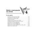
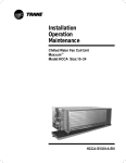
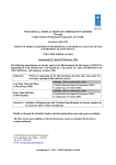
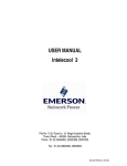
ROOFTOP PACKAGED UNITS
User Manual
INSTALLATION, OPERATION AND MAINTENANCE INSTRUCTIONS
Note: For your reference only, CARDIFF reserves the rights to change the
data without previous notice
Please kindly contact Cardiff in time if you
have special requirements.
1
COMPANY
WITH QUALITY
SYSTEM
CERTIFIED BY DNV
===ISO 9001:2000 ===
(1)BRIEF INTRODUCTION AND FEATURES
1) General Introduction
1. CARDIFF WRFZ series and WFZ series units are single packaged units which are factory assembled, tested
and shipped complete with compressor, evaporator and condenser coils, fans and controls, and these packages are
designed for outdoor installation mainly, and indoor installation as optional.
And they may be used for cooling only or heat pump, and efficient both when heating and cooling.
The units are ideal for residential, commercial and industrial applications and are available in nominal
tonnage from 3.0 to 53.0 tons for 50HZ.
Quality design and construction make bright air-cooled rooftop package units with hermetic scroll
compressors the preferred applications and easy installation and maintenance.
Operation range of outdoor temp. is from -10ºC to 43ºC.
2) Cardiff rooftop units APPLICATIONS
Rooftop packaged systems are unobtrusive, quiet, and designed to provide year round comfort – warming in Winter and cooling in
Summer. Cardiff wide product range offers a unit of performance capacity to suit small to large packaged air conditioner
applications, e.g. offices, shops, motels, fast food outlets, restaurants, petrol stations, open plan office and work spaces,
supermarkets, shopping malls and auditoriums.
Units are suited to high static pressure applications where large volume spaces are to be air conditioned. Long pipe and duct runs
are possible enabling greater installation flexibility.
This range of units has been developed to meet the needs of typical applications. Should you have special requirements, such as
higher air flows or greater sensible duty units contact your nearest Cardiff representative. Cardiff engineers have extensive
experience in designing air conditioning equipment for specific applications.
Typical installation:
2
4) Main Descriptions
. Unit description
A) Efficient. These reverse cycle (heat pump) air conditioners provide one of the most efficient forms of heating you can invest in.
For every 1 kW of power consumed, up to 3 kW of heat is generated. Each outdoor unit incorporates high efficiency scroll
compressors. Heat exchange coils use inner grooved tube for better heat transfer.
B) Performance. These systems have been designed and tested to perform in ambient conditions as low as -5°C and as high as
45°C. Belt drive fan motors are used to match the supply air requirements. The smaller units have 3 speed direct drive fans for
adjusting air flows.
C) Durable. Our packaged systems are built tough to withstand all weathers. Their durable construction ensures a long life and
excellent return on your investment. The outdoor air coils' aluminum fins are epoxy coated for extra protection in corrosive
environments, e.g. salt laden sea air. Cabinets are constructed from high grade steel - polyester powder coated for all weather
protection. External fasteners are stainless steel. Corrosion resistant drain trays are also included.
D) Insulation. Indoor air sections are generously insulated to reduce condensation and contain noise.
E) Safety. The refrigeration systems includes a number of protection facilities, including: HP and LP switches, anti rapid cycle
timers, circuit breaker control circuits, electronic de-ice switch and 24 V control
F) Economy. Some models feature the flexibility and economy of two stage operation. Compressors are progressively switched
on only as they are needed. This has the added advantage of lowering start-up current.
G) Economizer Option. If the outdoor air heat content or temperature is below that of the return air, a fresh air damper opens
and the return air damper closes to provide the first stage of cooling. Operating costs are reduced as the compressor(s) will only
operate to provide more cooling if it is required.
H) Fresh Air Introduction. An optional fresh air damper is available for most models. For applications using high
proportions of fresh air (50%+) a hot gas bypass and HP fan speed controller are recommended and are available as options.
I) Peace of Mind. The manufacturer operates a quality management system that conforms to international standard ISO 9001.
Cardiff products have been chosen, against worldwide competition, for use in some of the most exclusive projects — chosen
because of their proven efficiency, durability, performance, reliability and value.
G) Easy service. Quick release fasteners are provided on electrical and compressor panel.
H) Quiet design. Apartments are provided on electrical and compressor section, low noise.
. Components or assembly descriptions
A) Quiet operation
The package Rooftop series are basic constructed and engineered with noise reduction as a first consideration, low
noise mounted fans are used 15mm wave type acoustic Insulation for compressor section and compressors are
mounted on vibration isolators.
B) Low Cost Installation
Units are factory assembled and pre-charged with a single point electrical connection On arrival to the job site
they are ready to be lifted to their operating position through the lifting supports available on the units C) Capacities to Fit
There is a large production line of packaged units with capacities ranging from 3.0 to 53.0 for 50 Hz refrigeration
tons at nominal conditions 3
D) Casing
Heavy grade steel casing with polyester epoxy powder electrostatic oven-baked paint of coating finish designed
for outdoor Installation with 10mm Insulation for evaporator section only All units are provided with a 8mm
thickness aluminum frame filter that slides out or easy cleaning or replacement E) Compressor
The compressor used is hermetic refrigerant gas cooled with Internal thermal protection In each phase, scroll
type The terminal boxes are rain tight starting is direct-on-line With high efficiency low sound so as to match
all other Cardiff products’ reliability and efficiency.
F) Evaporator and Condenser Coils
The evaporator and condenser coils are designed to deliver their respective duties at optimum performance at all
design conditions Coils are manufactured from seamless copper tubes mechanically expanded into aluminum
fins All coils are tested at 30kg/cm2 (450 Psi) air pressure under water to avoid leakage They also undergo
dry chemical cleaning after manufacturing for optimum system cleanness G) Direct Driven Condenser Axial Fans
All condenser fans are of the Axial type which are directly mounted on the motor shaft All fans are selected for
optimum efficiency and for maximum sound power reduction.Fan blades are made for maximum corrosion
resistance and are statically and dynamically balanced before Installation Cardiff try its bests to ensure the low
noise
operation with high efficiency All condenser fans are equipped with wire guards H) Condenser Fan Motor
All fans motors are of totally enclosed air-cooled squirrel-cage type Internal thermal current overload protected,
with class “B” electrical insulation I) Belt Drive Evaporator Fan
Fans are of the forward curved centrifugal double inlet double width DIDW type that are designed for maximum
efficiency for uniform air distribution V belt driven with variable pitch pulley as optional All fans are
statical1y and dynamica1ly balanced to ensure quiet operation and smooth performance J) Evaporator Fan Motors
Motors are of the totally enclosed induction type with fan motor assembly placed on a floating base with a
flexible connection at the fan /casing interface The base itself is mounted on rubber in sheer vibration isolators to
eliminate noise and vibration transmission to buildings All fan motors of direct-driven are of the 3-speed type 4
highly efficient induction type motors totally enclosed air-cooled squirrel-cage type internal thermal current
protected and with class “B” insulation Fan motors with V-belt-driven type are of 1 speed type.
K) Filters
All Models are provided with 8mm thickness aluminum frame filter as standard features . Other filters are
available
upon request L) Drain Pan
All units are provided with a drain pan having drain connection from one side. The drain pan is insulated on the
underside to prevent condensation M) Insulation
All units are internally lined with 10mm thermal insulation for coil and fan section evaporator side only N) Easy Installation
The package Rooftop has a compact design. It is supplied as a complete package ready for operation, with
no extra controls or other items to be installed. The units have a single power point entry with simple connections.
All units are designed to ensure maximum compliance with international standards.
Quick start-up is assured once installation is complete, as each rooftop unit is manufactured in an ISO9001 listed
facility to guarantee quality. All units are tested at the factory to provide reliable start up.
5) Standard Features
A Standard features 1.
Easily accessible system components 2.
Ample space for easy access to power and control panels 3.
Heavy duty mounting chassis for the whole unit with lifting holes 4.
Anti vibration mounting compressor rubber type 5.
Weather proof, polyester epoxy powder electrostatic paint oven baked finish for sheet metal and base
frame 6.
All units are shipped out from factory tested and protecting devices seated against client requirement 7.
8mm Nylon filer as standard for Returning air inlet 8.
Single skin evaporator side with 10mm thermal installation 9. Condenser coil with treated blue fins.
10. Quick release fasteners to be provided on electrical and compressor apartment cabinet.
5
B Electrical features 1.
Control and power panels include the direct-on-line starting contactors for the compressors and condenser fan
motor 2.
Internal thermal motor protector for condenser and evaporator fan motor 3.
Compressor internal thermal protection 4.
Anti-recycling protection for compressors time delay -through microprocessor 5.
Crank case heater for each compressor 6.
Control circuit breaker 7.
24Volt as control voltage 8.
Microprocessor controller for model “120Z” and above with the following main functions a)
Compressor lead lag operation to ensure longer life for the compressors and equal running hours
between compressors b)
External remote ON OFF button for remote operation of the unit using external ON OFF switch or
connection to building management system c)
9.
Volt-free terminals available for general alarm indication signal to remote monitoring station One power supply input 10. High and low pressure safety switches capsule type factory Pre-set C Refrigeration features 1.
Hermetic scroll suction gas cooled compressor motor 2.
Filter drier disposable type ·
3.
Charging points pin valve 4.
Service valve on liquid line 5.
Thermostatic expansion valve 6
from all models 6.
Fully charged unit with Freon R22 7.
Solenoid Valve 8.
Oil equalizing lines installed between parallel installed compressors
6) Optional Features
A Construction options 1.
Metal mesh on condenser section 2.
Optional Supply / Return Air Configurations, optional bottom supply and return type 3.
Evaporator with treated Anti-corrosion protection for coils (Blue fins)for copper aluminum coils only 4.
“25mm (1”)” or “50mm(2”)” thick flat filter.
5.
Economizer option with fresh return and exhaust air dampers with cowl If this option is installed in the unit the unit has the ability to work with free cooling or free heating mode
allowing it to exploit the external environmental condition as much as possible since it avoids turning on the
heaters and the compressors This function can be achieved by controlling the opening closing of the
external air damper With reference to the difference between the outdoor air temperature std enthalpy
and the indoor air temperature std enthalpy 6.
7.
High Static condenser fan option will also required a sealed + drain condensing section.
Upgraded Evaporator Fan Motor Drives.
B Electrical options 1.
Power circuit breaker for each motor 2.
Main power molded case circuit breaker for the whole unit can also be available with an external handle as
an option 3.
Low ambient control The refrigeration systems in all unit are inherently designed to operate efficiently without extra controls or
modifications To permit the unit to operate In low ambient condition a head pressure control can be Installed
either by 7
ON OFF Condenser fans sequencing for models with 2 condenser fans 2 speed of the condenser fan motor 4.
Earth leakage relay for each compressor 5.
Earth leakage relay for the whole unit 6.
External overload relay for each motor 7.
Power factor correction capacitor
8.
Auto or manual provision for pump down operation of each compressor stop 9.
Building automation system interface Interfacing With other building management systems can be Achieved
by an optional card which can communicate with other devices using the serial communication port 10. Voltage monitor controller phase failure relay for monitoring the main incoming power supply for the unit
which provides protection from single-phasing under-voltage phase-voltage imbalance and
phase-nonsequence·.
C Refrigeration options 1.
Heat pump package unit with 4-way reversing valve suction accumulator is a standard feature in heat pump
option 2.
Pressure gauges for each refrigeration circuit high low pressure gauges 3.
New refrigerant application R410a and R407c 4.
Hot gas bypass where low-local situation occurs and where it is necessary avoid low suction pressure
and“compressor cycling” 5.
Extra refrigerant accessories such as suction accumulators for cooling units only receivers oil separators…etc 6.
Solenoid valve for heat pump mode 7.
High and low pressure controller for model 9Z and up to model 190Z 2 REFRIGERANT PIPING DIAGRAM
8
refrigerant liquid
1
COMPRESSOR
7
SINGLE WAY VALVE
2
HIGH PRESSURE SWITCH
8
EXPANSION VALVE
3
REVERSING VALVE
9
SINGLE WAY VALVE
4
LOW PRESSURE SWITCH
10
EXPANSION VALVE
5
PIN VALVE
11
DRY FILTER
6
OIL SEPARATOR
9
4
BODY DIMENSION
10
11
5
INSTALLATION, CONTROL OPERATION AND
MAINTENANCE
Read all instructions before proceeding with the installation and start up.
PREFACE
1) UNPACKING
Retain packing materials until the unit is operated and found to be in good condition. If the unit shows external or
internal damage, or does not operate properly, contact the transportation company and file a damage claim.
2) AFTER-SALES SUPPORT
CARDIFF is committed to customer service both during and after the sale. If you have questions concerning the
operation of your unit or the information of this booklet, contact our Sales Department. If your units fail to operate
properly, or if you have questions concerning spare parts or Service Contact, contact our Sales Department.
12
SECTION I: SAFETY
These instructions are primarily intended to assist qualified individuals experienced in the proper installation of
heating and/or air conditioning appliances. Some local codes require licensed installation/service personnel for this
type equipment. All installations must be in accordance with these instructions and with all applicable national and
local codes and standards.
We recommend that you read this instruction manual carefully before use to gain full advantage of the functions of
the unit and to avoid malfunction due to mishandling.
Read these instructions thoroughly before starting the installation. Follow all precautions and warnings contained
within these instructions and on the unit.
1. SAFETY CONSIDERATIONS
The unit is designed to provide safe and reliable service when operating within design specifications. To avoid
injury to personnel and damage to equipment or property when operating the equipment, the following safe
practices should be observed as a minimum.
Check the unit weight to be sure the lifting equipment is adequate.
Disconnect power to the unit before working on it.
Do not remove access panels or doors until fans have completely stopped.
Do not enter an enclosed fan cabinet or into the unit while the fan is running.
Protect materials when welding or flame cutting. Use suitable cloth to contain sparks. Have a fire
extinguisher at hand and ready for immediate use.
2. WARNING and CAUTION
The precautions described below are WARNING and CAUTION. These are very important precautions
concerning safety. Be sure to observe all of them without fail.
WARNING
The matters with possibilities leading to serious consequences such as death or serious injury due to erroneous
handling.
CAUTION
These are the matters with possibilities leading to injury or material damage due to erroneous handling including
probabilities leading to serious consequences in some cases.
Installation and servicing of air conditioning equipment can be hazardous due to system pressure and electrical
components. Only trained and qualified service personnel should install, repair or service air conditioning
equipment. Untrained personnel can perform basic maintenance functions of cleaning coils and filters and
replacing filters. All other operations should be performed by trained service personnel. When working on air
conditioning equipment, observe precautions in the literature, tags and labels attached to the unit and other safety
precautions that may apply.
3. ADDITIONAL WARNINGS
In addition to the specific warnings listed on the previous page the following general warnings apply to your
unit:
13
Performance of installation, operation, or maintenance procedures other than those described in this manual
may result in a hazardous situation and may void the manufacturer's warranty.
Transport the unit with care. Sudden jolts or drops can damage the refrigeration lines.
Observe all warning labels.
Never remove warning labels.
Never operate damaged or leaking equipment.
Always turn off the unit and disconnect the power cord from the power source before performing any service or
maintenance procedures, or before moving the unit.
Never operate equipment with damaged power cords.
Refer service and repairs to a qualified technician.
Do not overcharge with refrigerant.
SECTION II
INSTALLATION
1) INSTALLATION REQUIREMENTS
EQUIPMENT APPLICATION
Before beginning the installation, verify that the unit model is correct for the job. The unit model number is printed
on the data label.
Charge Adjustment
As stated previously, the system is pre-charged. If further charge is required to be added, this can be done by
CAREFULLY drawing LIQUID refrigerant only through the compressor suction pipe valve.
ELECTRICAL
All electrical work must be carried out by a qualified and licensed electrician. The installation must comply with
the current relevant standards wiring rules and local authority requirements. Wire sizing is the responsibility of the
installer, as it depends on the conditions and regulations applicable to each installation site. Refer to the electrical
drawing and specification of the unit for the electrical data. The electrical installation requirements are generally
as follows:
The air-conditioning unit shall be supplied directly from a distribution board through a mains lockable isolating
switch.
Pre punched holes have been provided in the unit casing for the isolating switch. Do not drill into the cabinet as
pipes may be located behind.
REQUIREMENTS AND CODES
The unit should be installed in accordance with all national and local codes and regulations which govern the
installation of this type of equipment. In lieu of local codes, the equipment should be installed in accordance with
National Electric Code, and in accordance with the recommendations made by the National Board of Fire
Underwriters.
14
UNIT LOCATION
The electric unit is designed only for outdoor installations. Choosing the location of the unit should be based on
minimizing the length of the supply ducts. Consideration should also be given to availability, service access, noise,
and shade. The unit installation shall avoid areas where condensate drainage may cause problems.
CLEARANCES
The units require certain clearances for proper operation and service. Installer must make provisions for
adequate ventilation air, normally 2000mm’s spaces all around the units. It’s required to place a anti wind/rain
hood 2000mm above the unit.
CAUTION
DO NOT PERMIT OVERHANGING STRUCTURES OR
SHRUBS TO OBSTRUCT CONDENSER AIR DISCHARGE
OUTLET, AIR INLET OR VENT OUTLETS.
AIR FILTER REQUIREMENT
A suitable air filter must be installed in the unit. This unit is supplied with air filters. Air filter(s) must be installed
ahead of the evaporator coil of this unit.
CAUTION
NEVER OPERATE UNIT WITHOUT A FILTER.
A FAILURE
TO FOLLOW THIS WARNING COULD RESULT IN A
PERSONAL INJURY OR DEATH.
2) UNIT INSTALLATION
GROUND LEVEL
If installing the unit at ground level, provide a concrete mounting pad separate from the building foundation. The pad
must be level to ensure proper condensate disposal and strong enough to support the unit’s weight.
UNCONDITIONED SPACES
All ductwork passing through unconditioned spaces must be properly insulated to minimize duct losses and prevent
condensation. Refer to local codes for any insulation material requirements.
RIGGING AND HOISTING
This unit is not designed to be handled with a fork-truck Exercise care when moving the unit. Rig the unit by
attaching chain or cable slings to the holes provided in lifting lugs. Spreaders MUST be used across the top of the
unit. Ensure the lifting equipment is adequate for the load. Keep the unit in an upright position at all times. The
rigging must be located outside the units center of gravity. Lifting plates may be removed after installation.
Typical lifting arrangement:
15
CAUTION
ALL ACCESS PANELS MUST BE SECURELY IN PLACE
WHEN RIGGING AND HOISTING.
MOUNTING
The unit should be fastened to a firm flat horizontal base plinth using the holes supplied in
the mounting rails.
When the unit is being installed on a roof it is recommended that the unit is installed on a
substantial structure with vibration isolating springs beneath the unit. These springs are not
supplied with the unit. Three channels are provided under the base for spring mounts or
bolting down.
Flexible duct connections are recommended between the supply and return ducts and the
unit.
16
SECTION III OPERATION
CHECK TESTS
1. Leave the on/off switch in the off position and close the mains isolating switch. A four hour
delay period is required to allow the crankcase heaters to drive any liquid refrigerant out of the
compressor oil.
2. Check that the shipping blocks beneath each compressor have been removed and that each
compressor is secure on its mounts.
3. Check that all fan motors are free running.
4. Check that the thermostat is correctly wired to the unit and is set at the desired temperature.
5. Check that the air filters have been correctly installed if fitted.
6. Check air diffuser dampers are open if appropriate.
START UP PROCEDURE
Use the supplied Commissioning Sheet to help you complete the following procedure:
1. After the four hour delay period has expired, switch on the unit.
System 1's compressor will start straight away. System 2's compressor will start six minutes later
due to the built in delay timer.
2. Check the supply voltage between each phase and neutral.
3. Compressors fitted are directional. Check for correct rotation. If rotation is incorrect the
compressor will not pump, be noisy, and will draw minimal current. To correct motor rotation,
change the phasing at the main power terminal.
4. Measure the current draw on each phase to the compressor motors and measure the current draw
of each fan motor. Check all readings against the specified values in the wiring diagram.
5. Fit gauges and measure the suction and discharge pressures of both refrigeration circuits.
6. Check that the outdoor air fan motors are running smoothly.
7. Test the operation of the reversing valve by running the unit in both the heating and cooling
mode.
8. Check the indoor unit's fan belt tension after 20 mins of operation and adjust if necessary (refer
Commissioning Sheet).
9. Check the supply air flow at each outlet.
10. Check the tightness of all electrical connections and sign the check label.
11. Touch up any outdoor unit paintwork damage to prevent corrosion.
CAUTION
THE UNIT IS EQUIPPED WITH CRANKCASE HEATERS.
ALLOW 24 HOURS PRIOR TO CONTINUING START UP
PROCEDURES TO ALLOW FOR HEATING OF THE
REFRIGERANT COMPRESSOR CRANKCASE. FAILURE
TO COMPLY MAY RESULT IN DAMAGE AND COULD
CASUE PREMATURE OF THE SYSTEM. THIS WARNING
SHOULD BE FOLLOWED AT INITIAL START UP AND
ANY TIME THE POWER HAS BEEN REMOVED FOR 12
HOURS OR LONGER.
17
START-UP CHECKLIST & COMMISSI ON IN GDATA
(Remove and hand to AC unit owner).
PRELIMINARY INFORMATION
MODEL No.
SERIAL No.
DATE
TECHNICIAN
PRE-START-UP (Insert checkmark in box as each item is completed).
1. VERIFY THAT ALL PACKING MATERIALS HAVE BEEN REMOVED FROM UNIT.
2. REMOVE ALL SHIPPING HOLDDOWN BOLTS AND BRACKETS, AS PER INSTALLATION INSTRUCTIONS.
3. CHECK ALL ELECTRICAL CONNECTIONS AND TERMINALS FOR TIGHTNESS.
4. CHECK THAT CONDENSATE CONNECTION IS INSTALLED, AS PER 3. INSTALLATION INSTRUCTIONS.
5. CHECK THAT INDOOR AIR FILTER IS CLEAN AND IN PLACE.
6.VERIFY THAT UNIT INSTALLATION IS LEVEL.
7.CHECK FANS FOR ALIGNMENT AND NOISE.
Record the following data after at least 20 minutes running time.
COMPRESSORS
No. 1
No. 2
Suction Pressure
Suction Line Temperature
Discharge Pressure
Liquid Line Temperature
KPa
KPa
°C
°C
KPa
KPa
°C
°C
Superheat
K
K
Subcooling
K
K
Compressor Amps
(L1)
A
A
Compressor Amps
(L2 for 3 phase)
A
A
Compressor Amps
(L3 for 3 phase)
A
A
Indoor fan Amps
(L1)
A
Indoor fan Amps
(L2)
A
Indoor fan Amps
(L3)
A
FANS
No. 1
No. 2
Outdoor fan Amps
(L1)
A
A
Outdoor fan Amps
(L2)
A
A
Outdoor fan Amps
(L3)
A
A
°C DB
°C WB
Indoor coil Return Temperature
Indoor coil Supply Temperature
°C DB
°C WB
Outdoor air Temperature
°C DB
°C WB
Length of liquid line
m
m
Length of suction line
m
m
l
l
Refrigerant, quantity charged
kg
kg
Supply voltage
V
V
Actual voltage
V
V
Oil level
18
SECTION IV MAINTAINENCE
MAINTENANCE
To ensure continuing high performance, and to minimize the possibility of premature equipment
failure, periodic maintenance must be performed on the air conditioning equipment. The units
should be inspected at least once each year by a qualified service person.
The minimum maintenance requirements for this equipment are as follows:
MAINTENANCE TIME SCHEDULE
4. Check for excessive noise and vibration and correct as
Monthly
necessary.
1. Check air filters, Replace throwaway
3.
type filters when they become clogged
operating pressures.
Check
suction
and
discharge
as necessary.
5. Check fan and motor bearings and lubricate or replace
4. Replace indoor air filters (if fitted).
6. Check for insulation and duct damage and repair as
with dust and lint or clean cleanable
type filters monthly.
2. Check condensate drain for free
drainage.
necessary.
3. Check compressor compartment for
5. Check condensate drain for free
7. Remove lint and dust accumulation from outdoor coil
oil stains indicating refrigerant leaks.
drainage.
fins.
Three Monthly (or every 1200
8. Touch up any paintwork damage to prevent corrosion.
hrs of operation)
Check the indoor unit's fan belt tension
and adjust if necessary.
Six Monthly
Inspect outdoor coil. Clean when necessary.
Yearly
1. Check all refrigerant piping for
Ensure that fan blades are clean and adequately balanced.
chafing and vibration.
1. Check the tightness of electrical
2. Check the operation of electric
Check refrigerant charge by measurement of superheat
connections.
heaters, if fitted.
and sub cooling where necessary, adjust charge and TX
valve to achieve optimum performance.
2. Check the tightness of all fans, motor
3. Check air supply at all diffusers.
mountings, pulleys and belt tension.
19
Check the tightness of electrical connections.