1
Home Theater BD Player
HTB3560/12/78 K/98/94/40/55
Service
Service Manual
TABLE OF CONTENTS
Page
. Location of PCB Boards,Version Variation and Repair Scenario Matrix....1-2
. Technical Specifications…………....………………………..............1-3
. Safety Instruction, Warning & Notes….……………………....….....1-4
. DFU Instruction..............................................................................2-1
. Mechanical and Dismantling Instructions…………........................3-1
. Software Upgrades ........................................................................4-1
. Trouble Shooting Chart………………………………………………. 5-1
. Wiring Diagram………………………………………..………..….….6-1
. Electrical Diagrams and Print-layouts..….…………………....….…7-1
. Votages and Waveforms for Connection Pins..….………………...8-1
. Pin Description & Block Diagrams of ICs..….………………..........9-1
. Set Mechanical Exploded view & Part list.…………………..….…10-1
. Revision List.................................................................................11-1
©Copyright 2011 Philips Consumer Electronics B.V. Eindhoven, The Netherlands
All rights reserved. No part of this publication may be reproduced, stored in aretrieval system or
transmitted, in any form or by any means, electronic, mechanical, photocopying, or otherwise
CLASS 1
LASER PRODUCT
without the prior permission of Philips.
GB
Published by Arya & Stephen - 1246 BU AVM Printed in The Netherlands Subject to modification
Version 1.3
3141 785 38343
PHILIPS
1-2
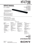
PCB BOARD LOCATION:
AMPLIFIER BOARD
MAIN BOARD
LOADER
POWER BOARD
FRONT CONTROL BOARD
VERSION VARIATIONS
Type / Versions
/12
/78
K/98
/94
40
55
MAIN BOARD
M
M
M
M
M
M
FRONT CONTROL BOARD
M
M +C
M +C
M +C M +C M +C
POWER BOARD
M
M +C
M +C
M +C M +C M +C
AMPLIFIER BOARD
M
M +C
M +C
M +C M +C M +C
Board in used
LOADER
*Tips:
Tips
Service Police
HTB3560
M
M
C -- Component Lever Repair
M
Module Lever
Repair
C -- Component
Lever
Repair
X -- Used
M
M
M
M
1-3
Production Specifications:
File formats
Note
6SHFLÀFDWLRQVDQGGHVLJQDUHVXEMHFWWRFKDQJHZLWKRXW
notice.
$PSOLÀHU
Region codes
The type plate on the back or bottom of the
home theater shows which regions it supports.
Country
Europe,
United Kingdom
DVD
A
Latin America
A
Australia,
New Zealand
Russia, India
China
BD
Asia Pacific, Taiwan,
Korea
Total output power: 300W RMS (30%
THD)
Frequency response: 20 Hz-20 kHz /
±3 dB
Signal-to-noise ratio: > 65 dB (CCIR) /
(A-weighted)
Input sensitivity:
AUX: 2 V
Music iLink: 1 V
Video
Signal system: PAL / NTSC
HDMI output: 480i/576i, 480p/576p, 720p,
1080i, 1080p, 1080p24
Audio
C
C
Media formats
Audio: .aac, .mka, .mp3, .wma, .wav
Video: .avi, .divx, .mp4, .mkv, .mpg, .mpeg,
.rmvb, .rm
Picture: .jpg, .jpeg, .gif, .png
AVCHD, BD, BD-R/ BD-RE, BD-Video,
DVD-Video, DVD+R/+RW, DVD-R/-RW,
DVD+R/-R DL, CD-R/CD-RW, Audio CD,
9LGHR&'69&'3LFWXUHÀOHV03PHGLD
WMA media, DivX Plus HD media, USB
storage device
S/PDIF Digital audio input:
Coaxial: IEC 60958-3
Optical: TOSLINK
Sampling frequency:
MP3: 32 kHz, 44.1 kHz, 48 kHz
WMA: 44.1 kHz, 48 kHz
Constant bit rate:
MP3: 32 kbps - 320 kbps
WMA: 48 kbps - 192 kbps
Radio
Tuning range:
Europe/Russia/China: FM 87.5-108
MHz (50 kHz)
$VLD3DFLÀF/DWLQ$PHULFD)0
MHz (50/100 kHz)
Signal-to-noise ratio: FM 50 dB
Frequency response: FM 200 Hz-12.5 kHz
/ ±6 dB
1-4
USB
Compatibility: Hi-Speed USB (2.0)
Class support: USB Mass Storage Class
(MSC)
File system: FAT16, FAT32, NTFS
Maximum memory support: < 160 GB
Rear speaker:
Output power: 2 x 50 W RMS (30% THD)
Speaker impedance: 4 ohm
Speaker drivers: 1 x 63.5 mm (2.5") woofer
Dimensions (WxHxD): 84.5 x 89 x 89 mm
Weight: 0.27 kg/each
Main unit
Remote control batteries
Power supply:
Europe/China/Russia/India: 220-240
V~, 50 Hz
/DWLQ$PHULFD$VLD3DFLÀF9a
50-60 Hz
Power consumption: 60 W
6WDQGE\SRZHUFRQVXPSWLRQ:
Dimensions (WxHxD): 360 x 58 x 325
mm
Weight: 2.4 kg
Subwoofer
Output power: 50 W RMS (30% THD)
Impedance: 4 ohm
Speaker drivers: 133 mm (5.25") woofer
Dimensions (WxHxD):
160 x 265 x 265 mm
Weight: 2.50 kg
Speakers
Center speaker:
Output power: 50 W RMS (30% THD)
Speaker impedance: 4 ohm
Speaker drivers: 1 x 63.5 mm (2.5") woofer
Dimensions (WxHxD): 84.5 x 89 x 89 mm
Weight: 0.27 kg
Front speaker:
Output power: 2 x 50 W RMS (30% THD)
Speaker impedance: 4 ohm
Speaker drivers: 1 x 63.5 mm (2.5") woofer
Dimensions (WxHxD): 84.5 x 159 x 80
mm
Weight: 0.35 kg/each
2 x AAA-R03-1.5 V
Laser
Laser Type (Diode): InGaN/AIGaN (BD),
AIGaInP (DVD/CD)
Wave length: 405 +7 nm/-7 nm (BD), 655
+10 nm/-10 nm (DVD), 790 +10 nm/-20
nm (CD)
Output power (Max. ratings): 20 mW
(BD), 6 mW (DVD), 7 mW (CD)
1-5
Safety instruction, Warning & Notes
Safety instruction
1. General safety
2.Laser safety
Safety regulations require that during a repair:
. Connect the unit to the mains via an isolation transformer.
. Replace safety components indicated by the symbol
,
only by components identical to the original ones. Any
other component substitution (other than original type)
may increase risk of fire or electrical shock hazard.
Safety regulations require that after a repair, you must
return the unit in its original condition. Pay, in particular,
attention to the following points:
. Route the wires/cables correctly, and fix them with the
mounted cable clamps.
. Check the insulation of the mains lead for external
damage.
. Check the electrical DC resistance between the mains
plug and the secondary side:
1) Unplug the mains cord, and connect a wire between
the two pins of the mains plug.
2) Set the mains switch the “on” position (keep the
mains cord unplug).
3)
Measure the resistance value between the mains
plug and the front panel, controls, and chassis
bottom.
4)
Repair
or
correct
unit
when
¡
measurement is less than 1M
the
resistance
.
5) Verify this, before you return the unit to the
customer/user (ref. UL-standard no. 1492).
6) Switch the unit “off”, and remove the wire between
the two pins of the mains plug.
This unit employs a laser. Only qualified service personnel
may remove the cover, or attempt to service this device
(due to possible eye injury).
Laser device unit
Type
: Semiconductor laser GaAlAs
Wavelength
: 650nm (DVD)
: 780nm (VCD/CD)
Output power
: 7mW (DVD)
: 10mW (DVD /CD)
Beam divergence: 60 degree
Note: Use of controls or adjustments or performance of
procedure other than those specified herein, may result in
hazardous radiation exposure. Avoid direct exposure to
beam.
1-6
Warning
1.General
2. Laser
. All ICs and many other semiconductors are susceptible to
. The use of optical instruments with this product, will
electrostatic discharges (ESD). Careless handing during
increase eye hazard.
repair can reduce life drastically. Make sure that, during
. Only qualified service personnel may remove the cover
repair, you are at the same potential as the mass of the
or attempt to service this device, due to possible eye
set by a wristband with resistance. Keep components and
injury.
tools at this same potential. Available ESD protection
with a disc loaded inside the player.
equipment:
1)
. Repair handing should take place as much as possible
Complete kit ESD3 (small tablemat, wristband,
connection box, extension cable and earth cable)
. Text below is placed inside the unit, on the laser cover
shield:
4822 310 10671.
2)
Wristband tester 4822 344 13999.
. Be careful during measurements in the live voltage
section. The primary side of the power supply , including
the heat sink, carries live mains voltage when you
CAUTION: VISIBLE AND INVISIBLE LASER
RADIATION WHEN OPEN, AVOID EXPOSURE
TO BEAM.
connect the player to the mains (even when the player is
“off”!). It is possible to touch copper tracks and/or
components in this unshielded primary area, when you
Notes:
service
Laboratories. The double-D symbol is trademarks of Dolby
the
player.
Service
personnel
must
take
precautions to prevent touching this area or components
in this area. A “lighting stroke” and a stripe-marked
printing on the printed wiring board, indicate the primary
side of the power supply.
. Never replace modules, or components, while the unit is
“on”.
Manufactured
under
licence
Laboratories, Inc. All rights reserved.
from
Dolby
1-7
6HUYLFH+LQWV
&$87,21
&+$5*('&$3$&,7256217+(6(592%2$5'0$<'$0$*(7+('5,9(
(/(&7521,&6:+(1&211(&7,1*$1(:'5,9(7+$7¶6:+<%(6,'(67+(6$)(7<
0($685(6/,.(
6:,7&+2))32:(56833/<
(6'3527(&7,21
$'',7,21$/$&7,2160867%(7$.(1%<7+(5(3$,57(&+1,&,$1
7KHIROORZLQJVWHSVKDYHWREHGRQHZKHQUHSODFLQJWKHGHIHFWLYHORDGHU
'LVPDQWOLQJRIWKHORDGHUWRDFFHVVWKH(6'SURWHFWLRQSRLQWLIQHFHVVDU\
6ROGHUWKH(6'SURWHFWLRQSRLQW 'LVFRQQHFWÀH[IRLOFDEOHIURPWKHGHIHFWLYHORDGHU
3XWDSDSHUFOLSRQWKHÀH[IRLOWRVKRUWFLUFXLWWKHFRQWDFWV¿J
5HSODFHWKHGHIHFWLYHORDGHUZLWKDQHZORDGHU
5HPRYHSDSHUFOLSIURPWKHÀH[IRLODQGFRQQHFWLWWRWKHQHZORDGHU
5HPRYHVROGHUMRLQWRQWKH(6'SURWHFWLRQSRLQW
$77(17,217KHODVHUGLRGHRIWKLVORDGHULVSURWHFWHGDJDLQVW(6'E\DVROGHUMRLQWZKLFKVKRUWFLUFXLWVWKHODVHUGLRGHWRJURXQG
)RUSURSHUIXQFWLRQDOLW\RIWKHORDGHUWKLVVROGHUMRLQWPXVWEHUHPRYHDIWHUFRQQHFWLRQORDGHUWRWKHVHW
Solder Joint
(6'SURWHFWLRQSRLQWLVDFFHVVLEOHIURPWRSRIORDGHU
2QO\DSSOLFDEOHIRUGHIHFWLYHORDGHUQHHGHGWREHVHQWEDFNWRVXSSOLHUIRUIDLOXUHDQDO\VLVDQGWRVXSSRUWEDFNFKDUJLQJ
HYLGHQFH
7KLVLVDOVRDSSOLFDEOHIRUDOOSDUWQHUVKLSZRUNVKRSV
1-8
Notes
Lead-Free requirement for service
INDENTIFICATION:
x
Regardless of special logo (not always indicated)
Use only original spare-parts listed in the
Service-Manuals. Not listed standard-material
(commodities) has to be purchased at external
One must treat all sets from 1.1.2005 onwards, according
next rules.
companies.
x
Important note: In fact also products a little older can also
be treated in this way as long as you avoid mixing
solder-alloys (leaded/ lead-free). So best to always use
SAC305 and the higher temperatures belong to this.
Special information for BGA-ICs:
- always use the 12nc-recognizable soldering
temperature profile of the specific BGA (for
de-soldering
always
use
highest
lead-free
temperature profile, in case of doubt)
Due to lead-free technology some rules have to be
respected by the workshop during a repair:
- lead free BGA-ICs will be delivered in so-called
‘dry-packaging’ (sealed pack including a silica gel
x Use only lead-free solder alloy Philips SAC305 with
order code 0622 149 00106. If lead-free solder-paste is
pack) to protect the IC against moisture. After
required, please contact the manufacturer of your
opening, dependent of MSL-level seen on
solder-equipment. In general use of solder-paste within
indicator-label in the bag, the BGA-IC possibly
workshops should be avoided because paste is not easy
still
to store and to handle.
communicated via AYS-website.
to
be
baked
dry.
This
will
be
Do not re-use BGAs at all.
x Use only adequate solder tools applicable for lead-free
solder alloy. The solder tool must be able
has
x
For sets produced before 1.1.2005, containing
o To reach at least a solder-temperature of 400°C,
leaded soldering-tin and components, all needed
o To stabilize the adjusted temperature at the
spare-parts will be available till the end of the
solder-tip
o To exchange solder-tips for different applications.
x Adjust your solder tool so that a temperature around
360°C – 380°C is reached and stabilized at the solder
joint. Heating-time of the solder-joint should not exceed
service-period. For repair of such sets nothing
changes.
x On our website:
www.atyourservice.ce.Philips.com
You find more information to:
~ 4 sec. Avoid temperatures above 400°C otherwise
BGA-de-/soldering (+ baking instructions)
wear-out of tips will rise drastically and flux-fluid will be
Heating-profiles of BGAs and other ICs used in
destroyed. To avoid wear-out of tips switch off un-used
Philips-sets
equipment, or reduce heat.
x Mix of lead-free solder alloy / parts with leaded solder
alloy / parts is possible but PHILIPS recommends
You will find this and more technical information
within the “magazine”, chapter “workshop news”.
strongly to avoid mixed
For additional questions please contact your local
solder alloy types (leaded and lead-free). If one cannot
repair-helpdesk.
avoid, clean carefully the
solder-joint from old solder alloy and re-solder with new
solder alloy (SAC305).
2-1
EN Before using your product, read all accompanying safety
information
MS Sebelum menggunakan produk anda, baca semua
maklumat keselamatan yang disertakan
ZH
CN
ൔႬӅఱĶ౬ᄋෲႹෟڼ
֩ρಊྔ༓
ZH Ԛ͂੬ؿଐکۂwᇼͱቇᚾֺτڃ፭ؿΪͲ༅
TW
User manual
Power Cord
HDMI
2-2
1
EN Connect the home theater
MS Sambungkan teater rumah
ZH
CN
৹ࢨࡉ๚႙ᄁ
ZH டᇃϭࡼჱ
TW
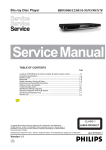
SUB
WOOFER
FRONT
LEFT
FRONT
CENTER
FRONT
RIGHT
STS3001
FRONT FRONT FRONT REAR REAR SUB
RIGHT LEFT CENTER RIGHT LEFT WOOFER
REAR
LEFT
FRONT
RIGHT
FRONT
LEFT
FRONT
CENTER
REAR
RIGHT
REAR
RIGHT
REAR
LEFT
SUB
WOOFER
2-3
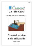
HDMI OUT (ARC)
HDMI (ARC) /
HDMI IN
AC MAINS~
2-4
2
EN Switch on the home theater
MS Hidupkan teater rumah
ZH
CN
չऻࡉ๚႙ᄁ
ZH ઢࡼჱ
TW
1
2
2-5
3
EN CoPSOHWHWKHÀUVWWLPHVHWXS
MS Lengkapkan persediaan kali pertama
ZH
CN
ຟӲ൲Օഥᇆ
ZH ѧιࠖωஉց
TW
HDMI
1
TV
2
3
4
HOME THEATER
5
6
HOME THEATER
2-6
4
EN Use your home theater
MS Gunakan teater rumah anda
ZH
CN
ൔႬࡉ๚႙ᄁ
ZH Ԛ͂੬ࡼؿჱ
TW
1
3
2
1
2
3
2-7
MUSIC iLINK
1
3
2
1
2
3
2-8
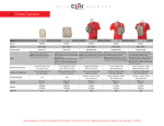
Your home theater
Congratulations on your purchase, and
ZHOFRPHWR3KLOLSV7RIXOO\EHQHÀWIURPWKH
VXSSRUWWKDW3KLOLSVRIIHUVHJQRWLÀFDWLRQ
of product software upgrade), register your
product at www.philips.com/welcome.
Remote control
This section includes an overview of the
remote control.
1
2
Main unit
This section includes an overview of the main
unit.
3
14
4
15
5
6
7
a Disc compartment
8
b Display panel
9
c
d
(Open/Close)
Open or close the disc compartment, or
eject the disc.
(Play/Pause)
Start, pause or resume play.
e SOURCE
Select an audio or video source for the
home theater.
f
(Standby-On)
Switch the home theater on or to standby.
16
17
18
10
19
11
12
13
20
21
2-9
a
(Standby-On)
Switch the home theater on or to
standby.
When EasyLink is enabled, press
and hold for at least three seconds
to switch all connected HDMI CEC
compliant devices to standby.
b
(Home)
Access the home menu.
c Source buttons
DISC/POP-UP MENU : Switch to disc
source.Access or exit the disc menu
when you play a disc.
RADIO : Switch to FM radio.
AUDIO SOURCE : Select an audio
input source.
d
BACK
Return to a previous menu screen.
In radio mode, press and hold to erase
the current preset radio stations.
e Navigation buttons
Navigate menus.
In radio mode, press left or right to
start auto search.
In radio mode, press up or down to
tune the radio frequency.
j
+/- (Volume)
Increase or decrease volume.
k
SOUND SETTINGS
Access or exit sound options.
l Alphanumeric buttons
Enter values or letters (using SMS style
entry).
m REPEAT
Select or turn off repeat mode.
n TOP MENU
Access the main menu of a disc.
o
OPTIONS
Access more play options while playing
a disc or a USB storage device.
In radio mode, set a radio station.
p
(Play)
Start or resume play.
q
(Pause)
Pause play.
r
(Mute)
Mute or restore volume.
s AUDIO
Select an audio language or channel.
f OK
&RQÀUPDQHQWU\RUVHOHFWLRQ
t SUBTITLE
Select subtitle language for video.
g
/ (Previous/Next)
Skip to the previous or next track,
FKDSWHURUÀOH
In radio mode, select a preset radio
station.
u Color buttons
Select tasks or options for Blu-ray discs.
h
(Stop) / (Eject/Open/Close)
Stop play.
Press and hold for three seconds to
open or close the disc compartment,
or eject the disc.
i
/
(Fast Backward / Fast Forward)
Search backwards or forward. Press
repeatedly to change the search speed.
3-1
Mechanical and Dismantling Instructions
Dismantling Instruction
Detailed information please refer to the model set.
The following guidelines show how to dismantle the player.
Step1: Remove 6 screws around the Top Cover, and then remove the Top Cover (Figure 1).
Figure 1
Step2: If it is necessary to dismantle Loader or Front Panel, the Front door should be removed first. (Figure 2)
Method A):Turn on the power button,then press open button to dismantle front door.Please kindly note that
power off as soon as front door is out of machine.
Method B): If the tray can’t open in normal way, you can make it through the instruction as below, an emergency eX it
at bottom cover of the machine.
Note: Make sure to operate gently otherwise the guider would be damaged.
Method A)
Method B)
Please kindly note that dismantle the front door
assembly carefully to avoid damage tray and the front door.
Figure 2
3-2
Mechanical and Dismantling Instructions
Detailed information please refer to the model set.
Dismantling Instruction
Step3 :Dismantle Front Panel, disconnect the connectors (XS604, XP12), need release 2 snaps of Front Panel & 2 snaps
of bottom cabinet , then gently pull the Panel out from the set. (Figure 3)
Figure 3
Step4 : Dismantle Front Control Board,remove 5 screws (Figure 4 )
Figure 4
Step5 : Dismantle Loader, disconnect the 3 connectors (XP3, XP2, XP6) aiming in the below figure, and remove 2 screws
that connects the loader and the bottom cabinet. (Figure 5)
Figure 5
3-3
Mechanical and Dismantling Instructions
Dismantling Instruction
Detailed information please refer to the model set.
Step6 : Dismantle Main Board, first disconnect 2 connectors (XP1, XP11), and then remove 5 screws. (Figure 5/6)
Step7: Dismantle Power Board, disconnect the connectors XP502 and CN502 on Power Board,then remove 5 screws.(Figure 5/6)
Step8: Dismantle Amplifier Board, remove 4 screws (Figure 5/6)
XP13
XS606
XP7
JI1
XP1
XS703
XS604 XP604 XP3
CN531
CN502
Figure 6
4-1
Software Upgrade
1. There are 2 ways to software upgrade:
First : Upgrade from USB: New a folder in root directory of USB and name it ‘UPG’. Copy the
upgrade file HTB3560.BIN to the UPG directory then press the HOME key on RC into HOME screen .Select ‘Setup’‐>’Advanced’‐>’Software update’‐>’USB’ in order and then press OK key . When upgrade file detected, select "Start" to upgrade, select
"Cancel" to cancel. After upgrading begins, a message “Do not switch off” will show, or
the product will hang up and upgrading failed.
After you cancel, the product would return setting screen and the software would not be upgraded. Second: Upgrade from Network: Keep the product connect to internet. press the HOME key on RC
into HOME screen .Select ‘Setup’‐>’Advanced’‐>’Software update’‐>’Network’ in order and then press OK key . When upgrade file detected, select "OK" to download, select
"Cancel" to cancel. After the software is downloaded, select to upgrade or cancel. After upgrading begins, a message “Do not switch off” will show, or
the product will hang up and upgrading failed.
After you cancel, the product would return setting screen and the software would not be upgraded. 2. Check the version information after upgraded. Press the Home key on RC , select ‘Setup’‐>’Advanced’‐>’Version information’ in order, and then press OK Key you will see a interface like below: Model:HTB3560/78 Version SystemSW:x.xx.xx Subsystem SW:xx‐xx‐xx‐xx Ethernet MAC:xx:xx:xx:xx:xx:xx EUI64:xx xx xx xx xx xx xx xx For information,frequently asked question and software updates,visit www.philips.com/support. Close 5-1
Trouble shooting Chart
VFD No display on Front Control Board
VFD No display on
Front Control Board
Go
Check every supply voltage on Main Board
whether normal or not.
(XP9, PIN6: +5V, PIN5: 12V)
No
Refer to XP501 on Power Board
Yes
Check voltage
+5V,+12V on
Power
No
Board at CN502 position and Front Control
Board at XP3
PIN10:+12V
Fix the connection XP3 on Front
Control Board and XP9 on Main Board
PIN9:+5V
Yes
Check the power key S608, open/closed key
S611, source key S609, paly/pause key
S610 on Front Board whether work normally
or not
No
Replace MCU U8 on Main Board, or
replace the Main Board
Yes
No
Check Front Control Board signals at XP3
Pin8 VSCLK, Pin7 VSDA,Pin6 VSTB
Check the XP3 ON Front Control Board Pin6,
7, 8 arrive the condition IC U301 PIN2,3,4
Yes
Check whether bad solder exists on XP3 on
Front Control Board and U301 of LED
No
Correct connection
Yes
Replace U301 or VFD
5-2
Trouble shooting Chart
keys do not work
keys do not work
Go
Check voltage +5V on Front Board U301
PIN7、PIN21
No
Fix the connection XP3 to XP9 on Main
Board
Yes
Check Front Control Board signals at XP3
Pin8 VSCLK, Pin7 VSDA,Pin6 VSTB
No
Replace U8 on Main Board, or
replace Main Board
Yes
Replace U301 on Front Board
5-3
Trouble shooting Chart
Remote control does not work
Remote
control
does not work
Go
Check battery of remote control whether
exhausted or not.
Yes
Replace the battery for remote
control
No
Check power supply of IR601 on Front
Control Board whether normal or not
XP3 Pin9 :+5V
Yes
Replace IR601
No
Check the +5V net on Front Control
Board to Main Board XP9
5-4
Trouble shooting Chart
No audio output
No audio output
Go
Check
voltage
+35.5V
(35.5V
Check XP13 Pin 14&16 3.3V on Main
for
HTB3560/78) for whether normal or not at
No
Board whether normal or not
on Amplifier Board
Yes
Yes
Refer to XP501 on
Power Board
Check the 24Pin FFC connection XP13 on
Main Board and XP701 on Amplifier Board
whether right or not between Main Board
and Amplifier Board
No
Yes
Check the control signal whether right or
not at the U8 Pin6, Pin7 on Main Board
and the signal at the XP13 Pin5 Pin7
No
Pin3
Replace U8 on Main Board or
replace Main Board
Yes
Replace
Amplifier Board
5-5
Trouble shooting Chart
No video output
No video output
Go
Check L452, R616 whether right on Main
Board
Add L452, R616
Yes
Check the video signal whether
right at U1: PIN B18 or
R615
No
Replace
No
Main IC or Main
Board
5-6
Trouble shooting Chart
Can’t read disc or can’t open the disk door
Can’t read disc or can’t
open the disk door
Go
Check loader work normally or not
No
Check XP7 on Main Board
Yes
Check 45Pin, 8Pin, 4Pin cable from
Main Board to Loader connect right or
not
Yes
Replace Loader
、
No
Fix 45Pin, 8Pin, 4Pin cable
5-7
Trouble shooting Chart
Tuner FM does not work
Tuner FM does not work
Go
Check voltage at Q28 C electrode
(+5V) on Main Board whether normal
or not
No
Refer to Power Board XP501
Yes
Check voltage +3.3V at Tuner
module (TUN1 Pin8) whether right or
not
No
Check Main Board tuner power supply
circuit.
Yes
Check Tuner module TUN1 Pin11,
Pin12 normal or not
No
Change the Tuner module
Yes
Check the U8
PIN25, PIN26, I2C
output on Main Board normal or not
Yes
Replace main Board
No
Check
Main
supply circuit
Board
U5
power
5-8
Trouble shooting Chart
AUX in does not work
AUX in does not
work
Go
Check voltage at U18 PIN16:5V on Main
Board whether normal or not
No
Refer to Power Board XP501
No
Check AUX IN connector
Yes
Check Main Board U18 Pin4, Pin11 signal
input whether right or not
Yes
Check U27 74HC4052
broken or not
Yes
Replace U27 4HC4052
whether
No
Check Main Board U5
5-9
Trouble shooting Chart
MP3 Link does not work
MP3 Link does
not work
Go
Check signal at JACK602 PIN3:MP3_R
PIN2:MP3_L ON front board whether normal or
not
No
Refer to Main Board XP604
No
Check Main Board C278, C279, R352,
Yes
Check Main Board U18 74HC4052 PIN2,
PIN15 L/R signal input right or not
R458,
Yes
Check voltage at U18 74HC4052
PIN16,VDD +5V, on Main Board
Whether normal or not
No
Refer to Power Board XP501
Yes
Check U27 74HC4052 whether broken
or not
No
Check Main Board U5
Yes
Replace U27 74HC4052
5-10
Trouble shooting Chart
COAX in does not work
COAX
in
does
not work
Go
Check voltage at U27 PIN6/PIN23:3.3V on
Main Board whether normal or not
No
Refer to Power Board XP501
Yes
Check Main Board U27 CS8416 PIN2 input
signal whether normal or not
No
Check Main Board C360,L11
Yes
Check U27 CS8416 whether broken.
or not
No
Check Main Board U8
Yes
Replace U27 CS8416
5-11
Trouble shooting Chart
Network in does not work
Network in does
not work
Go
Check P1 Pin2, Pin3, Pin5, Pin6 from
netting twine normal or not
Yes
Replace P1
No
Check netting twine link normal or
not
6-1
6-1
HTB3560/12/K98/94/40/55 BD HTS 300W (Equal)30%THD Block Diagram Draft
USB
WIFI
USB
DDR3
1Gb+2Gb
NAND
1Gb
Follow design
ASA LOADER
L9829B SANYO
415H09 OPU
RF
NEW design
SE
DRIVER
TPIC2050
ARC IN
50WX34R) 30%
CS8416
OPTI IN
MIC IN
SE
RJ45
DIR
CVBS Output
4558
DIR I2S
AUX IN
HDMI Output
I2C
TUNER
FM
Ricoh 5B700
I2S
MPEG Decoder
I2S
MTK8560
MP3 IN
4558
SE
STA309
Controls
74HC4052
STA518
AUDIO
PROCESSOR
PWM
50WX6(4R) 30%
SE
I2C
ADC
AK5358
SE
I2C
IR
STA518
CEC
SE
I2C
128Kb EEPROM
I2C
MCU
WT61P803
1K+256Byte SRAM
48KB Flash
FRONT PANEL LED 5-char 6202 DISPLAY)
KEY,LED
CONTROL
MGND +12V
DGND
+5V
+5V
POWER SUPPLY
AGND +35.5V
50W(4R) 30%
50W(4R) 30%
50W(4R) 30%
6-2
6-2
HTB3560/78 BD HTS400W (Equal)30%THD Block Diagram Draft
USB
WIFI
USB
DDR3
1Gb+2Gb
NAND
1Gb
ASA 9829+
SANY0 414H08
RF
SE
DRIVER
TPIC2050
DIR
ARC IN
SE
RJ45
68WX34R) 30%
CS8416
OPTI IN
CVBS Output
4558
STA516B
HDMI Output
I2C
STA309
DIR I2S
AUX IN
74HC405
2
I2S
MPEG Decoder
Controls
MTK8560
I2S
AUDIO
PROCESSOR
PWM
50WX6(4R) 30%
BTL
68W(8R) 30%
MP3 IN
4558
TUNER
FM
Ricoh 5B700
SE
I2C
ADC
AK5358
SE
I2C
IR
STA516B
CEC
SE
I2C
128Kb EEPROM
I2C
MCU
WT61P803
1K+256Byte SRAM
48KB Flash
FRONT PANEL LED 5-char 6202 DISPLAY)
KEY,LED
CONTROL
MGND +12V
DGND
+5V
+5V
POWER SUPPLY
AGND +35.5V
68W(4R) 30%
68W(4R) 30%
7-1
7-1
Front Board Circuit Diagram :
A
B
C
D
E
14PIN/1.0mm
XP3
+5V
R316
VSDA
100
100
100
MO_5V
0
VSDA
R637
R641
R639
R4
+12V
+5V
VSCLK
VSDA
VSTB
GND
R703
4.7K
IR
KEY_POW
NC\0
C768
100
R706
100
R707
100
VSDA
VSCLK
VSTB
R693
680
R23
MO_5V
NPN_MMBT8050CLT1
Q2
100pF/50V/NP0
0.1uF/50V/Y5V
C766
100pF/50V/NP0
C765
100pF/50V/NP0
C771
100pF/50V/NP0
C763
+12V
R708
R27
100pF/50V/NP0
C776
C774
100pF/50V/NP0
R320
10K
R698
R699
+
C777
0.1uF/25V/Y5V
CE611
47uF/16V
1
2
3
4
5
6
7
8
9
10
11
12
13
14
1K
1K
SEG1
SEG2
SEG3
SEG4
SEG5
SEG6
10K
C775
100pF/50V/NP0
ZD1
U301
DRIVER_LED_ET6202
OSC
DI/O
CLK
STB
KEY1
KEY2
VDD
SEG1/KS1
SEG2/KS2
SEG3/KS3
SEG4/KS4
SEG5/KS5
SEG6/KS6
SEG7/KS7
GND
GRID1
GRID2
GND
GRID3
GRID4
GND
VDD
SEG14/GRID5
SEG13/GRID6
SEG12/GRID7
SEG10/KS10
SEG9/KS9
SEG8/KS8
470
GRID3
GRID4
R696
GRID1
GRID2
GRID3
GRID4
GRID5
GRID6
GRID7
SEG1
SEG2
SEG3
SEG4
SEG5
SEG6
LED_J2808AG
S609
TAC020
SOURCE
1K
PLAY
TAC020
OPEN/CLOSE
S611
R640
D4
1
2
3
4
5
6
7
8
9
10
11
12
13
0.1uF/50V/Y5V
1N4148
R709
NC/33 LED+
C767
S610
D3
+5V
GRID1
GRID2
GRID3
GRID4
GRID5
GRID6
GRID7
SEG1
SEG2
SEG3
SEG4
SEG5
SEG6
GRID1
GRID2
MO_5V
GRID5
GRID6
GRID7
R318
1
LED
GRID[1:7]
28
27
26
25
24
23
22
21
20
19
18
17
16
15
SEG[1:6]
BZX79C5V6
R638
NC/33 LED-
R694
51K
R704 R705
4.7K 4.7K
KEY1
KEY2
GND
C769
To main board
14
13
12
11
10
9
8
7
6
5
4
3
2
1
100pF/50V/NP0
1
14
13
12
11
10
9
8
7
6
5
4
3
2
1
5.6K
+5V
2
IR
GND
VCC
GND
GND
1
2
3
4
5
USB_DM
IR
D5
C617
C618
47pF/50V/NP0
IRM_12mm
USB_DP
+
CE606
1uF/25V/Y5V NC/47uF/16V
NC/33pF/50V/NP0
NC/33pF/50V/NP0
R317
NC/2K
R319
MO_5V
Q1
USB_VCC
USB_DM
USB_DP
XS604
P801
USB-A/BK
R653
10K
LED1
R323
R644
1K
TAC020
R322
NC/0
A
FOR HTS3560˗XS605 FOR HTS2511
JACK602
1
6
3
+12V
R646
R609
5
12VA
2.2K
REFM
4
22K
+
3
CE608
220uF/16V
MIC JACK
C772
0.1uF/25V/Y5V
+
C611
2
3
FB615
R14
600/200mA
R690
47K
4
2
FB616
MP3_R
MP3_R
5
MP3_L
100
A
5
4
3
2
1
5PIN/2.0mm/100mm
XS606
MP3_L
R691
100
47K
A
5
4
3
2
1
R5
600/200mA
CE609
47uF/16V
5
2.2uF/50V
4
5.6K
R612
2
FB611
MIC JACK
600/200mA
680
C607
1000pF/50V/X7R
A
A
A
3
A
6
NC/0
5
C623
8
AS4558M
U602B
7
4
R648
3
2
2.2uF/16V/Y5V
R25
+
1
-
U602A
AS4558M
4
4
MIC
6
A
R642
100K
A
CE610
3
+
5
6
8
3
A
2
1
R11
-
6
47K
A
1
+
1
R610
22K
47pF/50V/NP0
R643
JACK601
STBY
S608
KEY_POW
NC/0
NC/LED_RED
R321
NC/1K
2
LED-
6
1
2
3
4
5
Shell A Shell B
XS605
4PIN/2.0mm/200mm
1
USB_VCC 4
3 4
2 1
3
2
USB_DM 3 2
1 2
USB_DP 4 3
1
4
4PIN/2.0mm/200mm
XS604
To main board
VCC
DD+
GND
TAC020
+5V
NC/NPN_3DG3904M
NC/4.7K
01UUSBJAK-101
1K
D6
LED+
IR601
1N4148
A
REFM
12VA
C610
R649
MIC
0
R645100K
20K
100pF/50V/NP0
C626
47pF/50V/NP0
C625
2.2uF/16V/Y5V
R692
R6
0
0
C773
A
A
100pF/50V/NP0
4
4
A
B
C
D
E
7-2
7-2
Power Board Circuit Diagram for HTB3560/12/K98/94/40/55:
C
D
R540A
CY506
R540B
470pF/250VAC
Alternative
VDD
C531
4700pF/400VAC
C533
1500pF/1KV
1
2
3
4
22
1
2
+33V
D533
2
47K/2W
R534
C538
0.1uF/50V/X7R
10A/200V
D531A
FR207/2A/1000V
R532
NC
D532
V
U531
TOP258EN
CONTROL
C536
0
R548
100pF/1KV
FR104/1A/400V
T531F 6
P
P-GND
R572
10K/1%
P
FB
4
C535 0.1uF/50V/X7R
R565
1K
U532
BPC-817B
3
R539
R543
C534
OP
10K
U533
AZ431LBZ
CE532
10uF/50V
C532
0.1uF/50V/X7R
R502D
Alternative
ZD531
BZX79C8V2
CX502
0.33uF/250VAC
CY501
470pF/250VAC
1
VDD
CY502
470pF/250VAC
R524
150
2
8
9
D562
T531P
T5011
EEL19
Q561
NPN_MMBT8050CLT1
D
HV
CY503
7T501P5
A11
A12
11
T531N
12
R505A
150K
R505B
150K
R505C
150K
C503
1000pF/1KV
R505D
150K
L503
3.3uH
Alternative
P
10
T501P24
P-GND
Alternative
FB
T501F2
3
T501G1
8T501N
S
Drain
NC
F501
D508
S
EN/UV
1
1
CY505
470pF/250VAC
22K
6
ZD502
BZX79C18
D506
FR107/1A/1000V
+
1M
1M
C504
2200pF/50V/X7R
D514
MBRF1045/10A/45V
FR107/1A/1000V
8
D509
SR360/3A/60V
D510
SR360/3A/60V
C502
0.47uF/63V
R523
R515
NC
Alternative
L502
CE504
47uF/35V
3.3uH
R518
2.49K/1%
100
+
CE509
2200uF/16V
+
CE510
1000uF/16V
C505
R516 10K
+
CE511
1000uF/16V
Alternative Alternative Alternative
R522
R511 470
R512
2.2K
1
2
U502
BPC-817B
3
100K
R526
ZD503
BZX79C11
4
2.2M
M+5V
PCON
3
CN502
8PIN/2.5mm/80mm
1
1:-24V
2 1
2:GND
3 2
3:+12V
4 3
4:GND
5 4
5
5:M+5V
6
6
6:M+5V
7
7
7:P_on/off
8
8
8:GND
Alternative
T501N
1N4148
2PIN/7.92mm
1
2
3
4
5
6
7
8
R513
22
Q501
PNP_MMBT8550CLT1
1
2
1
2
CE508
47uF/50V
T501F2
+
CE505
10uF/16V
Q502
PNP_MMBT8550CLT1
CN501
T501P5
D512
T501G4
D507
+12V
FR107/1A/1000V
+10V
R504
R517
NC
10 T501P24
2
R508
R509
R521
NC
Alternative
T501D3
R507
BP/M
S
CE507
470uF/16V
Alternative
8PIN/2.5mm
3
150
8
T3.15AH/250VAC
+
CE506
1000uF/16V
8T501N
4
S
VDR/560V
7
1
2
3
4
5
6
7
8
1
RV501
6
+
9
7
U501
TNY179PN
5
XP501
T501P12 SR3100/3A/100V
D513
5
Alternative
NC
2
T501
EF25
D505
FR107/1A/1000V
1M
TR501
NTC/3ohm/5A
R568
C563
1K
0.1uF/50V/X7R
R564
1K
C562
0.1uF/50V/X7R
R514
22
CY504
6T501P5
T531F6
R563
1K
D511
8T501N
470pF/250VAC
R501
C561
0.1uF/50V/X7R
1
3
T501D
NC
2
1K
Alternative Alternative
470pF/250VAC
HER203G/2A/200V
T531G5
PNP_3CG3906M
Q564
Q563
NPN_3DG3904M
Q562
NPN_MMBT8050CLT1
MBRX120/20V/1A
Remote on/off
Standby mode: Q561, D561 OFF; D562 ON
On mode: Q561, D561 ON; D562 OFF
9T501P12
C501
2200pF/1KV
6.6mH
CX501
0.33uF/250VAC
R502A
R502B
R579
1N4148
22
5
HV
T531D3
R569
1K
N.C
LIF501
RV504
200V/500A
R561
1.5K
R560
A8
A9
R570
100
U561
BPC-817B
R562
2.2K
R533
NC
D561
HV
R546
NC
ZD561
BZX79C33
OPP
T5311
ER28
R505
150
1.5K
R545
2.67K/1%
1
+
R567
2
6.6mH
R566
2.2K
0.1uF/50V/X7R
3
100
NC
+33V
2.2K
S X F
CE531
+
47uF/35V
NC
110K/1%
D535
1N4148
R573
1K
R542
R525
150
2
C573
0.1uF/50V/X7R
ZD532
BZX79C12
LIF502
R502C
1
OPP Circuit
R574
CE537
22uF/50V
R540
0
R538
6.8
R503
150
C571
0.1uF/50V/X7R
0
+
C
FB1
FB90@100MHz
R571
10 mR
OP
2 -
R550
33.2K/1%
R547
T531N
T531G 5
D
D536
1N4148
M+5V
4 -
R537
2M/5%
R541
1K
10
12
A10
A12
C539
0.01uF/400V
CE533
820uF/50V
R577
22K/1%
1
4
CE503
+
100uF/400V
D
+
D572
1N4148
1
CE502
+
100uF/400V
3
OPP
U571A
LM358/SO
2
CE501
+
100uF/400V
T531D
R576
1K
P
3
CE535
820uF/50V
+
C572
0.1uF/50V/X7R
+10V
3
1:+33V
2:+33V
3:+33V
4:GND
5:GND
6:GND
4
2
Alternative Alternative
1
Alternative
M+5V
+
C540
220pF/1KV
2
+ 1
BD501
KBP306
R544
33.2K/1%
N.C
R531
NC
+
1
Q571
PNP_MMBT8550CLT1
R578
10K
CN531
6PIN/2.5mm/70mm
1
2 1
3 2
4 3
5 4
6 5
6
2.9uH
R549
0
R536
2M/5%
R575
10
1
2
3
4
L531
8T531P
9
3
A8
A9
XP502 4PIN/2.5mm
8
1
HV
22
R540C
T531
PQ3230
E
22
PCON
B
3
A
DVD mode
T501:EEL19
U501:TNY177P
+12V:
D511:FR107
C503:NC
R514:NC
CE506:470uF/25V
CE507:220uF/25V
+5V:
D510:NC
CE509:1000uF/16V
CE510:NC
CE511:470uF/16V
3
0.1uF/50V/X7R
U503
AZ431LBZ
BD mode
T501:EF25
U501:TNY179P
+12V:
D511:HER203
C503:1000pF/1kV
R514:22/1206
CE506:1000uF/16V
CE507:470uF/16V
+5V:
D510:SR360
CE509:2200uF/16V
CE510:1000uF/16V
CE511:1000uF/16V
1
4
2
4
R520
NC
R519
2.4K/1%
* CAUTION :
THE PARTS MARKED WITH
ARE IMPORTANT PARTS ON THE SAFETY.
PLEASE USE THE PARTS HAVING THE DESIGNATED PARTS NUMBER WITHOUT FAIL.
A
B
C
D
E
7-3
Power Board Circuit Diagram for HTB3560/78:
7-3
C
D
R540B
1
Alternative
1
HV
VDD
47K/2W
R534
4 -
R537
2M/5%
D531A
FR207/2A/1000V
R532
NC
T531N
T531G 5
R551
470
V
D
CONTROL
D502
FR107/1A/1000V
D532
FR104/1A/400V
T531F 6
R547
R571
10 mR
P-GND
R572
10K/1%
ZD532
BZX79C12
OP
1M
1M
R505
NC
4
C532
0.1uF/50V/X7R
Alternative
HV
1
VDD
CY502
100pF/250VAC
R524
NC
2
3
R533
NC
A8
A9
8
9
D562
D561
T531P
HV
9T501P12
D
11
T531N
12
7T501P5
1
R505A
NC
ZD504
P6KE160A
8T501N
R505B
NC
R505C
NC
T531F6
T501F2
T501G1
2
6
8T501N
7
F501
8
R580
R569
NC
R579
Q564
NC
OPP
Q563
NC
2.2K
CE514
47uF/16V
R563
+
2.2K
C561
0.1uF/50V/X7R
2
NC
Q562
NC
C562
NC
R564
NC
C563
NC
R568
NC
Alternative
S
Drain
NC
S
BP/M
S
S
1
3
R507
1M
2PIN/7.92mm
1N4148
C502
0.47uF/63V
+
CE506
1000uF/16V
CE507
470uF/16V
150
EN/UV
Q502
PNP_MMBT8550CLT1
8T501N
1
R508
CE505
10uF/16V
ZD502
BZX79C18
D506
D514
MBRF1045/10A/45V
D516
+
T501P5
D508
-24V
+12V
FR107/1A/1000V
C504
2200pF/50V/X7R
T501F2
+10V
FR107/1A/1000V
CE504
47uF/35V
6
D512
FR107/1A/1000V
FR107/1A/1000V4
T501G
sty
8
D509
SR360/3A/60V
D510
SR360/3A/60V
Alternative
T501N
CE508
47uF/50V
R523
R515
NC
R518
2.49K/1%
+
CE509
2200uF/16V
+
CE510
1000uF/16V
C505
R516 10K
+
CE511
1000uF/16V
Alternative Alternative Alternative
R511 470
R512
2.2K
2.2M
U502
BPC-817B
3
ZD503
BZX79C11
PCON
1
2
3
4
5
6
7
8
3
CN502
8PIN/2.5mm/80mm
1
1:-24V
2 1
2:GND
3 2
3:+12V
4 3
4:GND
5 4
5
5:M+5V
6
6
6:M+5V
7
7
7:P_on/off
8
8
8:GND
Alternative
L502
100
M+5V
8PIN/2.5mm
R513
22
3.3uH
R522
100K
R526
1
2
3
4
5
6
7
8
R521
NC
Alternative
Q501
PNP_MMBT8550CLT1
1
2
1M
+
Alternative
10 T501P24
+
R504
9
T501D3
2
22K
R509
XP501
T501P12 SR3100/3A/100V
D513
5
4
CY505
100pF/250VAC
D507
L503
3.3uH
Alternative
7
U501
TNY179PN
1
T3.15AH/250VAC
1
2
T501
EF25
D505
FR107/1A/1000V
5
VDR/560V
CN501
R570
NC
R514
22
HER203G/2A/200V
P
Alternative
FB
NC
TR501
NTC/3ohm/5A
ZD561
NC
D511
10
T501P24
P-GND
C503
1000pF/1KV
470pF/250VAC
RV501
3
MBRX120/20V/1A
R505D
NC
CY504
6T501P5
1M
R501
BAS316/100V/0.5A
R566
NC
Alternative Alternative
100pF/250VAC
3
T501D
1M
R562
4.7K
Remote on/off
Standby mode: Q561, D561 OFF; D562 ON
On mode: Q561, D561 ON; D562 OFF
CY503
C501
2200pF/1KV
5
HV
A11
A12
T531G5
+33V
N.C
24mH
CX501
0.33uF/250VAC
R502A
R502B
1
C574
0.1uF/50V/X7R
U561
NC
R561
1.5K
Q561
NPN_MMBT8050CLT1
0
T5011
NC
T531D3
1.5K
R546
NC
R560
LIF501
RV504
NC
R545
2.67K/1%
Sty
T5311
NC
CX502
0.33uF/250VAC
CY501
NC
CE532
10uF/50V
0.1uF/50V/X7R
1
ZD531
BZX79C8V2
R567
1
R502D
C573
0.1uF/50V/X7R
R565
NC
C534
2
R502C
OP
110K/1%
C535 0.1uF/50V/X7R
R543
10K
U533
AZ431LBZ
4
2
R503
NC
+
R577
22K/1%
R574
CE537
22uF/50V
2
FB*2
D572
1N4148
2.2K
U532
BPC-817B
100
CE531
+
47uF/35V
D535
1N4148
R573
1K
LIF502
R525
NC
C571
0.1uF/50V/X7R
FB
R539
OPP Circuit
OPP
1
R542
S X F
R576
1K
U571A
LM358/SO
+
2 -
R550
33.2K/1%
0
P
R540
0
R538
6.8
D536
1N4148
+
C
100pF/1KV
FB1
FB90@100MHz
ZD533
BZX79C33
U531
TOP260EN
C536
CE533
820uF/50V
3
+
M+5V
0.01uF/400V
10
12
A10
A12
C539
NC
+
C572
0.1uF/50V/X7R
1
CE503
+
150uF/450V
R541
1K
C540
220pF/1KV
R548
0
1:+33V
2:+33V
3:+33V
4:GND
5:GND
6:GND
2
CE502
+
NC
D
CE535
820uF/50V
M+5V
+10V
+
3
R544
33.2K/1%
Q571
PNP_MMBT8550CLT1
R578
10K
CN531
6PIN/2.5mm/70mm
1
2 1
3 2
4 3
5 4
6 5
6
C538
0.1uF/50V/X7R
R575
10
1
2
3
4
4
CE501
3
T531D
Alternative Alternative
+33V
2.9uH
N.C
R531
NC
1
2
L531
R549
2
Alternative
1
2
3
4
0
3
+ 1
BD501
KBP306
1500pF/1KV
+
1
R536
2M/5%
C533
22
D533
10A/200V
2
8T531P
9
3
A8
A9
C531
4700pF/400VAC
2
22
R540C
T531
PQ3230
XP502 4PIN/2.5mm
4
100pF/250VAC
E
22
8
R540A
CY506
PCON
B
3
A
DVD mode
T501:EEL19
U501:TNY177P
+12V:
D511:FR107
C503:NC
R514:NC
CE506:470uF/25V
CE507:220uF/25V
+5V:
D510:NC
CE509:1000uF/16V
CE510:NC
CE511:470uF/16V
3
0.1uF/50V/X7R
U503
AZ431LBZ
BD mode
T501:EF25
U501:TNY179P
+12V:
D511:HER203
C503:1000pF/1kV
R514:22/1206
CE506:1000uF/16V
CE507:470uF/16V
+5V:
D510:SR360
CE509:2200uF/16V
CE510:1000uF/16V
CE511:1000uF/16V
1
4
2
4
R520
NC
R519
2.4K/1%
* CAUTION :
THE PARTS MARKED WITH
ARE IMPORTANT PARTS ON THE SAFETY.
PLEASE USE THE PARTS HAVING THE DESIGNATED PARTS NUMBER WITHOUT FAIL.
A
B
C
D
E
7-4
Amplifier Board Circuit Diagram for HTB3560/12/K98/94/40/55:STA309A
A
B
C
D
E
1
1
VD3.3V
D705
LL4148
Q702
R800
0/NC
PNP_MMBT8550CLT1
VD3.3V
TP47
TP19
TP45
TP18
TP2
TP39
TP38
TP46
R739
10K
C716
CE723
47uF/50V
XP701
TP41
D712
LL4148
R805
47K
Q701
DC714
NPN_3DG3904M
VD3.3V
AM_MUTE
R796
47K
PDWN R711
EAPD
33
CH1A
R767
1K
TP49
3.3V
TP40 +12V
GND
TP43
TH_WAR
PDWN
TH_WAR
C713
0.1uF/25V/Y5V
RESET
R701
33
AM_SDA
AM_SCL
R703
R702
33
33
ASDAT2
ASDAT1
ASDAT0
LRCLK
BCK
R709
R708
R707
R706
R705
1
2
3
4
5
6
7
8
9
10
11
12
13
14
15
16
D
33
33
33
33
33
D
25
26
C701
15pF/50V/NP0
C705
15pF/50V/NP0
D
MCK
R704
33
10K
VD3.3V
3.3V
FB712
500/800mA
VD3.3V
48
47
46
45
44
43
42
41
40
39
38
37
36
35
34
33
CH3A
CH4A
CH5A
C721
C720
C719
47pF/50V/NP0
D
C733
CH6A
2
C732
VD3.3V
47pF/50V/NP0
+
C718
0.1uF/25V/Y5V
CE721
22uF/16V
D
C712
0.1uF/25V/Y5V
R798
IC_84P_STA309A
OUT2A
OUT2B
NC
GND
VDD
OUT3A
OUT3B
OUT4A
OUT4B
OUT5A
OUT5B
NC
GND
VDD3.3V
OUT6A
OUT6B
C723
17
18
19
20
21
22
23
24
25
26
27
28
29
30
31
32
C710
D
+3.3V
0.1uF/25V/Y5V
FB711
500/800mA
MOV
GND
VDD3.3
GND
NC
SDI_78
SDI_56
SDI_34
SDI_12
LRCK1
BICK1
VDD3.3
GND
NC
RESET
PLLB
C717
0.1uF/25V/Y5V
CH2A
47pF/50V/NP0
TP50
TP48
1/2power-control
R712
10K
VD3.3V
64
63
62
61
60
59
58
57
56
55
54
53
52
51
50
49
U703
PDWN
SDIO_78
SDIO_56
NC
GND
VDD
SDO_34
SDI_12
LRCKO
BICKO
NC
GND
VDD
EPAD
OUT1A
OUT1B
D
TP44
TP42
C731
C715
0.1uF/25V/Y5V
0.1uF/25V/Y5V
R710 1K
47pF/50V/NP0
24PIN/0.5mm
ASDAT0
LRCLK
ASDAT1
ASDAT2
BCK
GND
MCK
GND
AM_SCL
AM_SDA
GND
AM_MUTE
RESET
47pF/50V/NP0
2
24
23
22
21
20
19
18
17
16
15
14
13
12
11
10
9
8
7
6
5
4
3
2
1
SA
SDA
SCL
XT1
FIL
NC
GNDA
VDDA
CKOUT
NC
GND
VDD3.3
OUT8_B
OUT8_A
OUT7_B
OUT7_A
TOP
D
27
28
0.1uF/25V/Y5V
+
47pF/50V/NP0
D
D
R777
10K
R713
10K
+ CE717
0.1uF/25V/Y5V
C724
22uF/16V
0.1uF/25V/Y5V
D
D
VD3.3V
R714
3.3K
FB715
500/800mA
3
3
C727
C729
1200pF/50V/X7R
100pF/50V/NP0
C728
220pF/50V/NP0
C730
0.1uF/25V/Y5V
+ CE704
C726
0.1uF/25V/Y5V
22uF/16V
R799
0
D
4
4
A
B
C
D
E
7-
7-5
Amplifier Board Circuit Diagram for HTB3560/12/K98/94/40/55:STA518
B
C
L708
D
E
10uH/5A
13
14
U701
IC_36P_STA518
36
35
C734
C735
0.1uF/50V/X7R
0.1uF/50V/X7R
34
33
D
CH6A
1
31
R716
CE705
27
+ C745
10K
100uF/16V
R717
10K
0.1uF/25V/Y5V
26
25
EAPD
24
FB713
75/200mA
20
0.1uF/50V/Y5V
19
0.1uF/25V/Y5V
IN1A
OUT2A
TH-WAR
OUT2A
FAULT
OUT1B
TRI-STATE
OUT1B
PWRDN
VCC1B
CONFIG
GND1B
VL
GND1A
VDD
VCC1A
VDD
OUT1A
GND-Reg
OUT1A
GND-CLEAN
NC
7
22uH/3.3A
11
C752
R719
12
10
1uF//50V/X7R
13
C751
680pF/50V/X7R
R727
10
C749
17
C777
R406
4.7K
0.1uF/50V/X7R
R722
4.7K
CE711
220uF/35V
CE713
C778
220uF/35V
C764
15
16
0.1uF/50V/X7R
C775
D
C768
0.47uF/63V
0.1uF/50V/X7R
R729
4.7K
0.1uF/50V/X7R
CE714
220uF/35V
R750
4.7K
0.1uF/50V/X7R
L704
+35.5V
18
22uH/3.3A
CE715
220uF/35V
R723
4.7K
CE719
220uF/35V
+35.5V
+
+
C774
0.1uF/50V/X7R
CE720
220uF/35V
U702
34
0.1uF/50V/X7R
33
CH5A
D
32
CH1A
31
CH2A
30
29
28
TH_WAR
27
CE707 +
C756
26
R736
10K
25
100uF/16V 0.1uF/25V/Y5V
EAPD
24
23
+3.3V
75/200mA
22
CE708
100uF/16V
21
C798
+
C758
20
0.1uF/50V/Y5V
19
0.1uF/25V/Y5V
VCC-Sign
SUB-GND
VCC-Sign
OUT2B
VSS
OUT2B
VSS
VCC2B
IN2B
GND2B
IN2A
GND2A
IN1B
VCC2A
IN1A
OUT2A
TH-WAR
OUT2A
FAULT
OUT1B
TRI-STATE
OUT1B
PWRDN
VCC1B
CONFIG
GND1B
VL
GND1A
VDD
VCC1A
VDD
OUT1A
GND-Reg
OUT1A
GND-CLEAN
NC
D
+
35
C754
CE724
220uF/35V
+
C769
0.1uF/50V/X7R
C765
0.1uF/50V/X7R
CE718
220uF/35V
CE716
220uF/35V
+
+
R749
4.7K
CE712
220uF/35V
C748
1uF//50V/X7R
C741
14
C753
0.47uF/63V
680pF/50V/X7R
IC_36P_STA518
36
C755
FB714
1
JK701
CON_12P_2GNDS
D
0.1uF/50V/X7R
R735
10K
D
2200uF/10V/NC
L703
10
820uF/50V
D
2
CE725
1000UF/25V
0.1uF/50V/X7R
C737
0.1uF/50V/X7R
9
CE710
D
2200uF/10V/NC
CE722
1000UF/25V
CE741
C776
D
8
R741
4.7K
R748 CE742
4.7K
6
D
+35.5V
R740
4.7K
+
TP20
TP21
TP22
TP23
TP24
TP25
VCC2A
C757
680pF/50V/X7R
C738
12
11
10
9
8
7
6
5
4
3
2
1
+
100uF/16V
6
5
4
3
2
1
GND2A
IN1B
1uF//50V/X7R
C736
C750
0.1uF/50V/X7R
6
5
4
3
2
1
21
C747
GND2B
IN2A
C743
0.47uF/63V 0.1uF/50V/X7R
5
+
XS703
6PIN/2.5mm
C797
+
IN2B
R718
10
1uF//50V/X7R
C740
4
12
11
10
9
8
7
6
5
4
3
2
1
+
22
CE706
VCC2B
22uH/3.3A/NC
+
23
+3.3V
OUT2B
VSS
3
SUBSUB+
SLSL+
SRSR+
CENCEN+
FLFL+
FRFR+
+
28
VSS
L702
2
+
29
CH4A
TH_WAR
OUT2B
+
30
CH3A
SUB-GND
VCC-Sign
+
32
VCC-Sign
TP26
TP27
TP28
TP29
TP30
TP31
TP32
TP33
TP34
TP35
TP36
TP37
1
GND
GND
A
1
2
L705
22uH/3.3A
2
R751
3
4
5
7
C744
C761
0.47uF/63V 0.1uF/50V/X7R
R754
4.7K
C779
C780
680pF/50V/X7R
C739
1uF//50V/X7R
6
4.7K
R720
10
1uF//50V/X7R
C742
C789
R728 4.7K
C760
9
R725
4.7K
R752
4.7K
D
8
C782
0.1uF/50V/X7R 0.1uF/50V/X7R
R726
4.7K
0.1uF/50V/X7R
D
0.1uF/50V/X7R
10
L706
22uH/3.3A
11
12
R731
10
13
1uF//50V/X7R
C759
1uF//50V/X7R
C746
14
15
16
C766
680pF/50V/X7R
C762
R733
10
17
18
C767
D
680pF/50V/X7R
L707
R732
4.7K
C770
0.47uF/63V
C773
0.1uF/50V/X7R
R753
4.7K
D
R734
4.7K
C771
0.47uF/63V
22uH/3.3A
C772
0.1uF/50V/X7R
0.1uF/50V/X7R
+35.5V
CE709
+
820uF/50V
C763
0.1uF/50V/X7R
CE740
3
D706
LL4148
4.7uF/50V
R742
1K
+
D
CE733
LL4148
D708
LL4148
4.7uF/50V
3
SUB+
SL+
+
D707
R743
1K
CE734
4.7uF/50V
R744
1K
SR+
+
CE735
LL4148
D710
LL4148
+
D709
4.7uF/50V
+
3
4
-
U705A
AS4558M
2
R765
5.6K
R773
15K
8
C785
0.1uF/25V/Y5V
+
R771
2.7K
CE732
4.7uF/50V
+12V
R746
1K
FR+
CE737
D711
LL4148
4.7uF/50V
R747
1K
FL+
CEN+
+
1
1/2power-control
4.7uF/50V
+
D
CE736
R745
1K
R761
10
R766
5.6K
R769
15K/1%
R770
150K
R768
68K
+ CE730
100uF/16V
R772
2K
R806 R807
2.2K 2.2K
R808 R809
2.2K 2.2K
R810 R811
2.2K 2.2K
D
C783
0.1uF/25V/Y5V
C781
0.1uF/25V/Y5V
D
D
D
D
U705B
AS4558M
6
+
5
4
-
4
8
7
4
A
B
C
D
E
7-6
7-6
Amplifier Board Circuit Diagram for HTB3560/78:STA309A
A
B
C
D
E
1
1
D705
LL4148
Q702
PNP_MMBT8550CLT1
D
Q701
1K
NPN_3DG3904M
PDWN
TH_WAR
33
33
ASDAT2
ASDAT1
ASDAT0
LRCLK
BCK
R709
R708
R707
R706
R705
33
33
33
33
33
D
25
26
C701
15pF/50V/NP0
C705
15pF/50V/NP0
D
MCK
R704
33
10K
VD3.3V
C706
15pF/50V/NP0
3.3V
FB712
500/800mA
C731
VD3.3V
D
R777
10K
C712
0.1uF/25V/Y5V
+3.3V
R798
0.1uF/25V/Y5V
C710
FB711
500/800mA
1
2
3
4
5
6
7
8
9
10
11
12
13
14
15
16
D
D
MOV
GND
VDD3.3
GND
NC
SDI_78
SDI_56
SDI_34
SDI_12
LRCK1
BICK1
VDD3.3
GND
NC
RESET
PLLB
STA309A
CH1A
R721
OUT2A
OUT2B
NC
GND
VDD
OUT3A
OUT3B
OUT4A
OUT4B
OUT5A
OUT5B
NC
GND
VDD3.3V
OUT6A
OUT6B
48
47
46
45
44
43
42
41
40
39
38
37
36
35
34
33
33
C717
0.1uF/25V/Y5V
CH2A
2
R722
R723
R724
33
33
33
CH3A
CH4A
CH5A
R725
R726
C721
C720
33
33
C719
CH6A
CH6B
C723
D
C733
D
C732
VD3.3V
CE721
22uF/16V
+
C718
0.1uF/25V/Y5V
D
C725
47pF/50V/NP0
47pF/50V/NP0
D
D
R713
10K
+ CE717
C724
22uF/16V
0.1uF/25V/Y5V
33
VD3.3V
64
63
62
61
60
59
58
57
56
55
54
53
52
51
50
49
U703
R712
10K
C713
0.1uF/25V/Y5V
PDWN
SDIO_78
SDIO_56
NC
GND
VDD
SDO_34
SDI_12
LRCKO
BICKO
NC
GND
VDD
EPAD
OUT1A
OUT1B
33
R703
R702
R715
SA
SDA
SCL
XT1
FIL
NC
GNDA
VDDA
CKOUT
NC
GND
VDD3.3
OUT8_B
OUT8_A
OUT7_B
OUT7_A
1/2power-control
R701
AM_SDA
AM_SCL
EAPD
47pF/50V/NP0
TP50
TP48
RESET
C715
0.1uF/25V/Y5V
47pF/50V/NP0/NC
TP43
3.3V
+12V
33
47pF/50V/NP0/NC
GND
R711
R767
1K
TP42
TH_WAR
PDWN
0.1uF/25V/Y5V
D
TP44
TP49
TP40
C714
VD3.3V
R796
47K
47pF/50V/NP0
24PIN/0.5mm
R710
0.1uF/25V/Y5V
47pF/50V/NP0
XP701
D712
LL4148
AM_MUTE
C716
47K
100uF/16V
17
18
19
20
21
22
23
24
25
26
27
28
29
30
31
32
2
ASDAT0
LRCLK
ASDAT1
ASDAT2
BCK
GND
MCK
GND
AM_SCL
AM_SDA
GND
AM_MUTE
RESET
+ CE723
D
TOP
27
28
R805
47K
TP41
24
23
22
21
20
19
18
17
16
15
14
13
12
11
10
9
8
7
6
5
4
3
2
1
VD3.3V
R739
TP47
TP19
TP45
TP18
TP2
TP39
TP38
TP46
D
+12V
0.1uF/25V/Y5V
D
D
VD3.3V
3
R714
3.3K
C729
220pF/50V/NP0
1200pF/50V/X7R
100pF/50V/NP0
C730
3
FB715
500/800mA
C728
C727
0.1uF/25V/Y5V
+ CE704
C726
0.1uF/25V/Y5V
22uF/16V
R799
0/1%
D
4
4
A
B
C
D
E
7-7
Amplifier Board Circuit Diagram for HTB3560/78:STA518
7-7
D
32
CH6A
31
30
0.1uF/25V/Y5V
C745
26
25
24
100uF/16V
22
C797
C747
+
0.1uF/25V/Y5V
21
0.1uF/50V/Y5V
20
TH-WAR
OUT2A
FAULT
TRI-STATE
9
10
VL
GND1A
VDD
VCC1A
VDD
OUT1A
GND-Reg
OUT1A
13
C748
14
C741
1uF//50V/X7R
1uF//50V/X7R
C749
16
C751
D
C768
C460
0.47uF/63V
L705
22uH
CE710
+
CE718
D
30
29
28
TH_WAR
27
R735
10K
26
R736
10K
CE707 +
C756
100uF/16V 0.1uF/25V/Y5V
25
EAPD
24
+3.3V
23
FB714
22
75/200mA
CE708
21
C798
+
C758
20
0.1uF/25V/Y5V 0.1uF/50V/Y5V
19
100uF/16V
220uF35V
R758
4.7K
CE720
220uF35V
VCC-Sign
SUB-GND
VCC-Sign
OUT2B
VSS
OUT2B
VSS
VCC2B
IN2B
GND2B
IN2A
GND2A
IN1B
VCC2A
IN1A
OUT2A
TH-WAR
OUT2A
FAULT
OUT1B
TRI-STATE
OUT1B
PWRDN
VCC1B
CONFIG
GND1B
VL
GND1A
VDD
VCC1A
VDD
OUT1A
GND-Reg
OUT1A
GND-CLEAN
NC
2
L706
3
4
R720
10
1uF//50V/X7R
C742
C789
5
CE719 220uF35V
6
7
CE724
220uF35V
2
C462
R754
4.7K
R756
4.7K
R757
4.7K
D
9
0.1uF/50V/X7R
10
L707
11
12
22uH
R731
10
13
C766
680pF/50V/X7R
1uF//50V/X7R
C759
1uF//50V/X7R
C746
14
15
16
C762
D
C767
680pF/50V/X7R
R733
10
17
18
D
C744
C760
8
L708
0.1uF/50V/X7R
C770
0.47uF/63V
C771
0.47uF/63V
R732
4.7K
C463
0.1uF/50V/X7R
D
R734
4.7K
C464
0.1uF/50V/X7R
22uH
+40V
+
CE709
3
C763
3
0.1uF/50V/X7R
820uF/50V
XS703
4
3
2
1
TP21
TP22
TP23
TP24
D706
D
CE740
LL4148
+40V
D707
22uF/16V
CE733
D708
LL4148/NC
4.7uF/50V/NC
CE734
4.7uF/50V/NC
R743
1K/NC
LL4148
D710
LL4148
CE735
4.7uF/50V
+
D709
U705A
AS4558M
2
+
3
4
-
R765
5.6K
1
R773
15K
C785
8
+
R771
2.7K
CE732
4.7uF/50V
+12V
4.7uF/50V
D711
CE737
LL4148
4.7uF/50V
+
1/2power-control
CE736
R766
5.6K
R761
R745
1K
R746
1K
+
D
R744
1K/NC
+
LL4148/NC
D
R772
2K
0.1uF/25V/Y5V
R769
15K/1%
R770
150K
R768
68K
R747
1K
SUB+
SL+
SR+
FR+
FL+
CEN+
+ CE730
100uF/16V
R806
22K
R807
2.2K
R808
2.2K
R809
2.2K
R810
2.2K
R811
2.2K
10
D
D
C783
0.1uF/25V/Y5V
C781
0.1uF/25V/Y5V
4
R742
1K
+
C765
0.1uF/50V/X7R
C774
0.1uF/50V/X7R
C769
0.1uF/50V/X7R
4PIN/2.5mm
D
+
4
3
2
1
4
D
D
D
U705B
AS4558M
6
+
5
4
-
8
7
A
13
14
+40V
22uH
0.47uF/63V
680pF/50V/X7R
C739
1uF//50V/X7R
GND
GND
220uF35V
1
0.1uF/50V/X7R
31
CH2A
CE716
+
32
220uF35V
JK701
CON_12P_2GNDS
D
220uF35V
+
33
CE714
+
D
34
220uF35V
1
CE712
220uF35V
220uF35V
+
0.1uF/50V/X7R
0.1uF/50V/X7R
CH5A
CH1A
35
C754
CE713
R764
4.7K
CE715
U702
C755
4.7K
R760
4.7K
STA516B
2
R763
+40V
18
820uF/50V
36
R762
4.7K
CE711
680pF/50V/X7R
0.1uF/50V/X7R
17
D
C458
0.47uF/63V
680pF/50V/X7R
0.1uF/50V/X7R
C764
R727
10
C451
0.1uF/50V/X7R
+
D
10
15
NC
22uH
C772
+
GND-CLEAN
22uH
L704
R719
12
GND1B
L703
C752
11
VCC1B
CONFIG
C456
0.1uF/50V/X7R
8
OUT1B
PWRDN
0.1uF/50V/X7R
7
OUT1B
C455
0.1uF/50V/X7R
0.47uF/63V
C750
0.1uF/50V/X7R
19
OUT2A
R404
6.2
+
CE706
IN1A
C457
680pF/50V/X7R
0.1uF/50V/X7R
C738
1uF//50V/X7R
C737
+
75/200mA
VCC2A
C736
6
C454
0.1uF/50V/X7R
R403
6.2
12
11
10
9
8
7
6
5
4
3
2
1
+
+3.3V
23
GND2A
IN1B
5
1uF//50V/X7R
+
FB713
IN2A
4
12
11
10
9
8
7
6
5
4
3
2
1
C467
27
GND2B
22uH
R718
10
C470
EAPD
28
R717
10K
IN2B
C740
C465
10K
+
CE705
100uF/16V
VCC2B
L702
3
C469
R716
VSS
2
C466
29
TH_WAR
OUT2B
C468
CH6B
CH3A
CH4A
OUT2B
VSS
D
SUBSUB+
SLSL+
SRSR+
CENCEN+
FLFL+
FRFR+
0.1uF/50V/X7R
33
D
VCC-Sign
0.1uF/50V/X7R
1
34
1
0.1uF/50V/X7R
35
C735
0.1uF/50V/X7R
SUB-GND
D
C734
0.1uF/50V/X7R
VCC-Sign
0.1uF/50V/X7R
TP26
TP27
TP28
TP29
TP30
TP31
TP32
TP33
TP34
TP35
TP36
TP37
C474
0.1uF/50V/X7R
U701
C472 C473
0.1uF/50V/X7R
0.1uF/50V/X7R
STA516B
36
C471
C452
0.1uF/50V/X7R
C453
0.1uF/50V/X7R
0.1uF/50V/X7R
D
E
0.1uF/50V/X7R
C
0.1uF/50V/X7R
B
0.1uF/50V/X7R
A
B
C
D
E
7-8
Front Control Board Print-layout (top side):
7-8
7-9
7-9
Power Supply Print-layout (top side) for HTB3560/12/K98/94/40/55:
7-10
7-10
Power Supply Print-layout (top side) for HTB3560/78:
7-11
7-11
Amplifier Board Print-layout (top side) for HTB3560/12/K98/94/40/55:
7-12
7-12
Amplifier Board Print-layout (bottom side) for HTB3560/12/K98/94/40/55:
7-13
7-13
Amplifier Board Print-layout (top side) for HTB3560/78:
7-14
7-14
Amplifier Board Print-layout (bottom side) for htb3560/78:
8-1
8-1
Voltages for per connection pin
XP9--From Main Board Connect to Front Board
Pin No
Pin Assin
Remarks
1
Reserved
2
Reserved
3
GND
4
-24V_D
5
12V
11.4-12.6V
6
VCC
4.75-5.25V
7
VFD_CLK
SPI
8
VFD_DATA
9
VFD_STB
10
GND
11
IR_OUT
12
POWER_KEY
3.3V
13
GND
14
GND
XP13--From Main Board Connect to Amp Board
Pin No
Pin Assin
Remarks
1
DATA0
2
LRCKL
I2S
3
DATA1
4
DATA2
5
BCLK
6
GND
7
MCLK
I2S
8
GND
9
AMP_SCL
IIC
10
AMP_SDA
11
GND
12
AMP_MUTE
13
AMP_RST
14
3.3V
3.2-3.4V
15
+12V_D
11.4-12.6V
16
3.3V
3.2-3.4V
17
+12V_D
11.4-12.6V
18
GND
19
GND
20
POWER_derating
21
Reserved
22
TH_WAR
23
PDWN
24
BKND_ERR
XP1--From Main Board Connect to Power Board
Pin No
Pin Assin
Remarks
1
-24V
22.8V-25.2V
2
GND
3
+12V
11.4-12.6V
4
GND
5
VCC
4.75-5.25V
6
VCC
4.75-5.25V
7
VCC_D
4.75-5.25V
8
GND
XP6--From Main Board Connect to Front USB
Pin No
Pin Assin
Remarks
1
USB_VCC
4.75-5.25V
2
GND
3
USB_M1
High spped
difference
4
USB_P1
8-2
8-2
Waveforms for measure point
XP13 Pin20_POWER_derating
XP13 Pin10 _AMP SDA
XP13 Pin12_ AMP MUTE
XP13 Pin5_AOBCK
XP13 P13_AMP RST
XP13 P9_
AMP SCL
XP13 Pin7_AOMCLK
XP13 Pin4_AOSDATA2
8-3
8-3
Waveforms for measure point
XP13 Pin1_AOSDATA0
XP13 Pin22 _TH_WAR
XP13 Pin3_AOSDATA1
XP13 Pin2 _AOLRCK
XP13 Pin23 _PDWN
9-1
U1 Main IC-MT8560_BAAG Functional Block Diagram
NAND
1GB
DDR3
256/384MB
7.1 CH
2 CH
OPU
MT8560
Motor
Driver
Ethernet
HD+SD Decode
810MHz ARM11
400MHz AudioDSPx3
HDMI 1.4
Ethernet
S/PDIF
HDMI
Component
CVBS
DVO
USB
Audio
DAC
9-2
U1 Main IC-MT8560_BAAG Pin Assignment
9-3
U409 Motor Drivers IC‐ TPIC2050 1. Block Diagram 2. Pin assignment 9-4
9-5
3. Pins definition 9-6
U26 Audio A/D IC ‐AK5358K 1. Block diagram 9-7
3. Pin Function 9-8
U531 Internal IC Diagram-TNY179EN on Power Board:
9-8
9-9
9-9
U534 Internal IC Diagram-TOP260EN on Power Board:
9-10
U534 IC TOP258EN Diagram on Power Board:
9-10
10-1
Exploded View of HTB3560/12 /78 K/98 /94/40/55:
11-1
REVISION LIST
Version 1.0
* Initial release for HTB3560/12/78
Version 1.1
* Initial release for HTB3560K/98
Version 1.2
* Initial release for HTB3560/94
Version 1.3
* Initial release for HTB3560/40/55