1
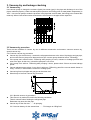
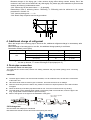
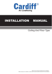
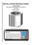
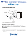
2. CONDENSING UNIT INSTALLATION
TYPICAL INSTALLATION
TO
POWER
SUPPLY
TO
INDOOR
BLOWER
24 V c
o n tr o
l s ig n
WEATHERPROOF
DISCONNECT
SWITCH
al
TO
COIL
Chart 18
Seal opening(s) with
permagumor equivalent
NOTE: All outdoor wiring must be weatherproof
INSTALLATION PRECAUTION
To install properly, please read this manual at first.
The air conditioner must be installed by qualified persons.
When all the installation work is finished, please turn on the power only after a thorough check.
No further announcement if there is any change of this manual caused by product improvement.
Note: The installer should illustrate to users how to correctly use and maintain the air-conditioner, as well as
remind users to carefully read and keep both Installation Manual and Owner's Manual well.
Notes Before Installation
1. Select the correct carry-in path.
2. Move this unit as originally packaged as possible.
3. f the air conditioner is installed on a metal part of the building, it must be electrically insulated according
to the relevant standards to electrical appliances.
4. Installation work must be performed in accordance with the national wiring Standards by authorized
personnel only.
INSTALLATION PLACE
The Outdoor Unit
There is enough room for installation and maintenance.
The air outlet and the air inlet are not impeded, and cannot be reached by strong wind.
The place is dry and ventilative.
The support is flat and horizontal and can stand the weight of the outdoor unit. And no additional noise or
vibration.
Your neighborhood will not feel uncomfortable with the noise or expelled air.
There is no leakage of combustible gas.
It is easy to install the connecting pipe or cables
CONDENSING UNIT INSTALLATION
MCAC-UTSM-2008-02
Cautions Location in the following places may cause malfunction of the machine. (If unavoidable, please
consult your local dealer.)
a. There exists petrolatum.
b. There is salty air surrounding(near the coast).
c. There is caustic gas(the sulfide, for example) existing in the air (near a hot spring).
d. The Volt vibrates violently(in the factories).
e. In buses or cabinets.
f. In kitchen where it is full of oil gas.
g. There is strong electromagnetic wave existing.
h. There are inflammable materials or gas.
i. There is acid or alkaline liquid evaporating.
j. Other special conditions.
Note: remark per EMC Directive 89/336/EMC for to prevent flicker impressions during the start of the
compressor (technical process).
Following installation conditions apply.
1. The power connection for the air conditioner has to be done at the main power distribution, the
distribution has to be of a low impedance, normally the required impedance reaches at a 32A fusing
point.
2. no other equipment has to be connected with the power line.
3. for detailed installation acceptance, please refer to your contact with the power supplier if restrictions do
apply for products like washing machine, air conditioner or electrical ovens.
4. for power details of the air conditioner, refer to the rating plate of the product.
5. for any question contact your local dealer.
3. Vacuum dry and leakage checking
3.1 Vacuum Dry
Use vacuum pump to change the moisture (liquid) into steam (gas) in the pipe and discharge it out of the
pipe to make the pipe dry. Under one atmospheric pressure, the boiling point of water(steam temperature) is
100℃. Use vacuum pump to make the pressure in the pipe near vacuum state, the boiling point of water falls
relatively. When it falls under outdoor temperature, the moisture in the pipe will be vaporized.
3.2 Vacuum dry procedure
There are two methods of vacuum dry due to different construction environment: common vacuum dry,
special vacuum dry.
3.2.1Common vacuum dry procedure
l Vacuum dry (for the first time)---connect the all-purpose detector to the inlet of liquid pipe and gas pipe,
and run the vacuum pump more than two hours (the vacuum pump should be below -755mmHg)
l If the pump can’t achieve below -755mmHg after pumping 2 hours, moisture or leakage point will still
exist in the pipe. At this time, it should be pumped 1 hour more.
l If the pump can’t achieve -755mmHg after pumping 3 hours, please check if there are some leakage
points.
l Vacuum placement test: place 1 hour when it achieves -755mmHg, pass if the vacuum watch shows no
rising. If it rises, it shows there’s moisture or leakage point.
l Vacuuming from liquid pipe and gas pipe at the same time.
l Sketch map of common vacuum dry procedure
l
l
.
3.2.2 Special vacuum dry procedure
This vacuum dry method is used in the following conditions:
There’s moisture when flushing the refrigerant pipe.
Rainwater may enter into the pipe.
Vacuum dry for the first time ······ 2h pumping
3.2.3 Vacuum destroy for the second time ······ Fill nitrogen to 0.5Kgf/cm2
Because nitrogen is for drying gas, it has vacuum drying effect during vacuum destroy. But if the
moisture is too much, this method can’t dry thoroughly. So, please pay more attention to prevent water
entering and forming condensation water.
3.2.4 Vacuum dry for the second time-------1h pumping
Determinant: Pass if achieving below -755mmHg. If -755mmHg can’t be achieved in 2h, repeat
procedure 5.2.3 and 5.2.4.
3.2.5 Vacuum placing test --------1h
3.2.6 Sketch map of special vacuum dry procedure.
4. Additional charge of refrigerant
When the length of the one-way pipe is less than 5m, additional refrigerant charge is unnecessary after
vacuuming.
When the length of one-way pipe is over 5m, the additional charge quantity is as follows:
Calculation method: (unit in gram)
Refrigerant
Liquid diameter(mm/inch)
Unit amount (g/m)
Formula
Φ6.35(1/4”)
30
(L-5)×30
Φ9.53(3/8”)
65
(L-5)×65
Φ12.7(1/2”)
90
(L-5)×90
R22
Remark:1. The additional refrigerant charge is simply related with the liquid pipe diameter.
2. In the up formula, “L” means total length of liquid pipe(unit: m).
5. Drain pipe connection
5.1 Install the indoor unit drain pipe
The outlet has PTI screw bread, Please use sealing materials and pipe sheath (fitting) when connecting
PVC pipes.
CAUTIONS
l
l
l
l
l
l
The drain pipe of indoor unit must be heat insulated, or it will condense dew, as well as the connections
of the indoor unit.
Hard PVC binder must be used for pipe connection, and make sure there is no leakage.
With the connection part to the indoor unit, please be noted not to impose pressure on the side of indoor
unit pipes.
When the declivity of the drain pipe downwards is over 1/100, there should not be any winding.
The total length of the drainpipe when pulled out traversely shall not exceed 20m, when the pipe is too
long, a prop stand must be installed to prevent winding.
Refer to the figures on the right for the installation of the pipes.
1.5m~2m
Put as deep as possible
(about 10cm)
Bend
S shape
Insulating Downward declivity
material lower than 1/100
5.2 Drainage test
Downward declivity
lower than 1/100
Check whether the drainpipe is unhindered
New built house should have this test done before paving the ceiling.
VP30
6. Wiring
Please refer to the Wiring Diagram.
7. Test operation
Note: To avoid personal injury or death, do not supply power to unit with compressor terminal-box cover
removed.
Be sure field wiring complies with local and national fire, safety, and electrical codes, and voltage to system
is within limits shown on unit-rating plate. Contact local power company for correction of improper voltage.
7.1 The test operation must be carried out after the entire installation has been completed.
7.2 Please confirm the following points before the test operation:
l The indoor unit and outdoor unit are installed properly.
l Tubing and wiring are correctly completed.
l The refrigerant pipe system is leakage-checked.
l The drainage is unimpeded.
l The heating insulation works well.
l The ground wiring is connected correctly.
l The length of the tubing and the added stow capacity of the refrigerant have been recorded.
l The power voltage fits the rated voltage of the air conditioner.
l There is no obstacle at the outlet and inlet of the outdoor and indoor units.
l The gas-side and liquid-side stop valves are both opened.
l The air conditioner is pre-heated by turning on the power.
7.3 Test operation
Set the air conditioner under the mode of “cooling”, and check the following points as the “Owner’s Manual”.
If there is any malfunction, please refer to chapter “Troubles and Causes”in the “Owner’s Manual”.
7.3.1 The indoor unit
l Whether the room temperature is adjusted well.
l Whether the indicator lights normally.
l Whether the drainage is normal.
l Whether there is vibration or abnormal noise during operation.
7.3.2 The outdoor unit
l Whether there is vibration or abnormal noise during operation.
l Whether the generated wind, noise, or condensed water by the air conditioner have influenced your
neighborhood.
l Whether any of the refrigerants is leaked.
Cautions:
1.
2.
A protection device delays the start of compressor for about 3 minutes when it is restarted immediately
after switching on the power.
To prevent compressor damage or personal injury, observe the following:
Do not overcharge system with refrigerant.
Do not operate unit in a vacuum or at negative pressure.
Do not disable low-pressure switch.