Transcript
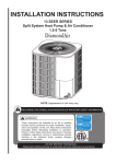
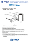
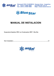
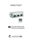
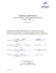
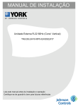
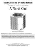
This document is customer property and is to
remain with this unit.
These instructions do not cover all the different variations of systems nor does it provide for every
possible contingency to be met in connection with
installation.
All phases of this installation must comply with
NATIONAL STATE AND LCOAL CODES. If additional
information is required please contact your local
distributor.
TABLE OF CONTENTS
INSTALLATION MANUAL
CONTENT
PAGE
1.0 SAFETY..................................................................................................................1
1.1 INSPECTION....................................................................................................1
1.2 LIMITATION......................................................................................................1
2.0 GENERAL..............................................................................................................1
3.0 UNIT INSTALLATION............................................................................................2
3.1 LOCATION.......................................................................................................2
3.2 GROUND INSTALLATION...............................................................................2
3.3 ROOF INSTALLATION.....................................................................................3
3.4 UNIT PLACEMENT..........................................................................................3
3.5 PRECAUTIONS DURING LINE INSTALLATION.....................................................3
3.6 PRECAUTIONS DURING BRAZING OF LINES......................................................3
3.7 PRECAUTIONS DURING BRAZING SERVICE VALVE..........................................4
3.8 FACTORY-PREFERRED TIE-DOWN METHOD......................................................4
3.9 REMOVING THE TOP PANEL AND MOTOR..........................................................5
4.0 ELECTRICAL CONNECTIONS......................................................................................5
4.1 GENERAL INFORMATION & GROUNDING ..........................................................5
4.2 FIELD CONNECTIONS POWER WIRING .............................................................5
5.0 EVACUATION................................................................................................................6
6.0 SYSTEM CHARGE.......................................................................................................6
6.1 MEASUREMENT METHOD....................................................................................6
6.2 SUB-COOLING CHARGING METHOD..................................................................6
7.0 SYSTEM OPERATION..................................................................................................6
7.1 COMPRESSOR CRANKCASE HEATER (CCH).....................................................6
7.2 HIGH-PRESSURE SWITCH FAULT (HEAT PUMP ONLY).....................................6
7.3 LOW-PRESSURE SWITCH (HEAT PUMP ONLY)..................................................7
7.4 TEMPERATURE SENSOR (HEAT PUMP ONLY)...................................................7
8.0 INSTRUCTING THE OWNER.......................................................................................7
8.1 MAINTENANCE......................................................................................................7
CONDENSING UNITS
1.5-5Tons
1.0 SAFETY
This is a safety alert symbol. When you see this
symbol on labels or in manuals, be alert to the potential for
personal injury.
This is an attention alert symbol. When you see this
symbol on labels or in manuals, be alert to the potential for personal injury.
Understand and pay particular attention to the signal words
DANGER, WARNING, or CAUTION.
An all-pole disconnection device which has at least 3mm
clearances in all poles , and have a leakage current that may
exceed 10mA, the residual current device (RCD) having a
rated residual operating current not exceeding 30mA, and
disconnection must be incorporated in the fixed wiring in
accordance with the wiring rules.
1.1 INSPECTION
As soon as a unit is received, it should be inspected for
possible damage during transit. If damage is evident, the
extent of the damage should be noted on the carrier's delivery
receipt. A separate request for inspection by the carrier's
agent should be made in writing. See Local distributor for
more information.
Requirements For Installing/Servicing R22 Equipment
● Gauge sets, hoses, refrigerant containers, and recovery
system must be designed to handle the POE or PVE type oils.
● Manifold sets should be 800 PSIG high side and 250 PSIG
low side with 550 PSIG Iow side restart.
● All hoses must have a 700 PSIG service pressure rating.
● Leak detectors should be designed to detect refrigerant.
● Recovery equipment (including refrigerant recovery
containers) must be specifically designed to handle R22.
● Do not use an R410A TXV.
● A liquid-line filter drier is required on every unit. see the Fig.1
DANGER indicates an imminently hazardous situation, which, if not
avoided, will result in death or serious injury.
WARNING indicates a potentially hazardous situation, which, if not
avoided, could result in death or serious injury.
CAUTION indicates a potentially hazardous situation, which, if not
avoided may result in minor or moderate injury. It is also used to
alert against unsafe practices and hazards involving only property
damage.
WARNING
Improper installation may create a condition where the
operation of the product could cause personal injury or
property damage.
Improper installation, adjustment, alteration, service or maintenance can cause injury or property damage. Refer to this
manual for assistance or for additional information, consult a
qualified contractor, installer or service agency.
CAUTION
RECOGNIZE THIS SYMBOL AS AN INDICATION OF IMPORTANT SAFETY INFORMATION
This product must be installed in strict compliance with the
installation instructions and any applicable local, state, and
national codes including, but not limited to building, electrical, and mechanical codes.
WARNING
These instructions are intended as an aid to qualified licensed service personnel for
proper installation, adjustement and operation of this unit. Read these instructions
thoroughly before attempting installation or operation. Failure to follow these instruction
may result in improper installation, adjustment, service or maintencance possibly resulting in fire, electrical shock, proerty damage, personal injury or death.
WARNING
FIRE OR ELECTRICAL HAZARD
Failure to follow the safety warnings exactly could result in
serious injury, death or property damage.
A fire or electrical hazard may result causing property
damage, personal injury or loss of life.
The appliance shall be installed in accordance with national
wiring regulations.
DO NOT DESTROY THIS MANUAL
Please read carefully and keep in a safe place for future reference by a serviceman.
Do not operate your air conditioner in a wet room such as a
bathroom or laundry room.
LIQUID
SERVICE VALVE
LIQUID-LINE
FILTER-DRIER
Fig.1 Filter-Drier insatllation
1.2 LIMITATIONS
The unit should be installed in accordance with all National, State
and Local Safety Codes and the limitations listed below:
1. Limitations for the indoor unit, coil and appropriate
accessories must also be observed.
2. The outdoor unit must not be installed with any duct
work in the air stream. The outdoor fan is the propelle type
and is not designed to operate against any additional
external static pressure.
3. The maximum and minimum conditions for operation
must be observed to assure a system that will give
maximum performance with minimum service.
4. This unit is not designed to operate with a low ambient
kit. Do not modify the control system to operate with any
kind of Iow ambient kit.
5. The maximum allowable line length for this product is 75
feet.
2.0 GENERAL
The outdoor units are designed to be connected to a matching
indoor coil with sweat connect lines. Sweat connect units are
factory charged with refrigerant for a matching indoor coil plus
25 feet of field supplied lines.
Installation manual
1
Matching indoor coils are available with a thermal expansion valve or an orifice liquid feed sized for the most common usage. The
orifice size and/or refrigerant charge may need to be changed for some indoor-out-door unit combinations,elevation differences
or total line lengths.
W
AIR DISCHARGE
ALLOW 60” MINIMUM CLEARANCE.
NOTE: GRILL APPEARANCE
MAY VARY.
CONTROL WIRING
1-11/32” (34.5mm)
L
POWER WIRING
7/8” (22.2mm)
LIQUID LINE
CONNECTION
VAPOR LINE
CONNECTION
Insulated Liquid Line
Fig.3 Tubing Hanger
3.7 PRECAUTIONS DURING BRAZING SERVICE VALVE
Precautions should be taken to prevent heat damage to
service valve by wrapping a wet rag around it as shown in Fig. 6.
Also, protect all painted surfaces, insulation, during brazing.
After brazlng cool joint with wet rag.
The outdoor unit must be connected to the indoor coil
using field supplied refrigerant grade copper tubing that
is internally clean and dry. Units should be installed only
with the tubing sizes for approved system combinations. The charge given is applicable for total tubing
lengths up to 25 feet.
Valve can be opened by removing the plunger cap and fully
inserting a hex wrench into the stem and backing out
counter-clockwise until valve stem just touches the chamfered
retaining wall.
Connect the refrigerant lines using the following procedure:
Dimensions (Inches)
18000
24000
36000
36000
36000
36000
"L" in [mm]
21-7/8[554]
21-7/8[554]
21-7/8[554]
23-5/8[600]
23-5/8[600]
23-5/8[600]
Liquid in
1/4
3/8
3/8
3/8
3/8
3/8
36000
36000
36000
48000
48000
29-7/8[759]
24-15/16[633]
29-7/8[759]
29-7/8[759]
29-7/8[759]
21-7/8[554]
28[710]
28[710]
28[710]
28[710]
21-7/8[554]
28[710]
28[710]
28[710]
28[710]
3/8
3/8
48000
29-7/8[759]
29-7/8[759]
29-7/8[759]
33-3/16[843]
23-5/8[600]
23-5/8[600]
28[710]
28[710]
23-5/8[600]
23-5/8[600]
28[710]
28[710]
3.0 UNIT INSTALLATION
3.1 LOCATION
Before starting the installation, select and check the suitability
of the location for both the indoor and outdoor unit. Observe
all limitations and clearance requirements. The outdoor unit
must have sufficient clearance for air entrance to the
condenser coil, for air discharge and for service access. See
Fig.5.
NOTE
For multiple unit installations, units must be spaced a
minimum of 18 inches apart. (Coil face to coil face.)
If the unit is to be installed on a hot sun exposed roof or a
black-topped ground area, the unit should be raised
sufficiently above the roof or ground to avoid taking the
accumulated layer of hot air into the outdoor unit.
Provide an adequate structural support.
3.2 GROUND INSTALLATION
Using a larger than specified line size could result in
oil return problems. Using too small a line will result in
loss of capacity and other problems caused by insufficient refrigerant flow. Slope horizontal vapor lines at
least 1" every 20 feet toward the outdoor unit to facilitate proper oil return.
Vapor in
1/2
5/8
3/4
3/4
3/4
7/8
3/4
3/4
3/4
3/4
7/8
3/4
3/4
3/4
3/4
3/8
3/8
3/8
3/8
3/8
3/8
3/8
1. Remove the cap and Schrader core from both the liquid
and vapor service valve service ports at the outdoor
unit. Connect Iow pressure nitrogen to the liquid line
service port.
NOTE
Refrigerant Connection
Service Valve Size
"W" in [mm]
21-7/8[554]
21-7/8[554]
21-7/8[554]
23-5/8[600]
23-5/8[600]
23-5/8[600]
60000
60000
Tape
Correct Incorrect
FIG.2 DIMENSIONS
"H" in [mm]
24-15/16[633]
24-15/16[633]
24-15/16[633]
29-7/8[759]
24-15/16[633]
24-15/16[633]
60000
Dry nitrogen should always be supplied through the
tubing while it is being brazed, because the temperature required is high enough to cause oxidation of the
copper unless an inert atmosphere is provide. The
flow of dry nitrogen should continue until the joint has
cooled. Always use a pressure regulator and safety
valve to insure that only low pressure dry nitrogen is
introduced into the tubing.Only a small flow is necessary to displace air and prevent oxidation.
The maximum length of refrigeration lines for outdoor
to indoor unit should not exceed 75 feet.
AIR INLETS LOUVERED PANELS
ALLOW 18” MINIMUM CLEARANCE
DIMENSIONAL DATA
Unit Model
(Btu/h)
3.4 UNIT PLACEMENT
CAUTION
Sheet Metal Hanger
Insulated Vapor Line
When installing units on a roof, the structure must be
capable of supporting the total weight of the unit, including a padded frame unit, rails, etc., which should be
used to minimize the transmission of sound or vibration
into the conditioned space.
1. Provide a base in the pre-determined location.
2. Remove the shipping carton and inspect for possible
damage.
3. Compressor tie-down bolts should remain tightened.
4. Position the unit on the base provided.
H
SERVICE ACCESS
ALLOW 24” CLEARANCE
3.3 ROOF INSTALLATION
3.5 PRECAUTIONS DURING LINE INSTALLATION
1. Install the lines with as few bends as possible. Care
must be taken not to damage the couplings or kink
the tubing. Use clean hard drawn Copper tubing
where no appreciable amount of bending around
obstruction is necessary, if soft copper must be used,
care must be taken to avoid sharp bends which may
cause a restriction.
2. The lines should be installed so that they will not obstruct
service access to the coil, air handling system or filter.
The unit may be installed at ground level on a solid base that
will not shift or settle, causing strain on the refrigerant lines
and possible leaks. Maintain the clearances shown in Fig.5
and install the unit in a level position.
Normal operating sound levels may be objectionable if the unit
is placed directly under windows of certain rooms (bedrooms,
study, etc.).
Top of unit discharge area must be unrestricted for at least 6
feet above the unit.
WARNING
The outdoor unit should not be installed in an area where
mud or ice could cause personal injury.
Elevate the unit sufficiently to prevent any blockage of the air
entrances by snow in areas where there will be snow accumulation. Check the local weather bureau for the expected snow
accumulation in your area. Isolate the unit from rain gutters to
avoid any possible wash out of the foundation.
3. Care must also be taken to isolate the refrigerant lines
to minimize noise transmission from the equipment to
the structure.
4. The vapor line and liquid line must be insulated with a
minimum of 1/2" foam rubber insulation (Armafiex or
equivalent). Tape and suspend the refrigerant lines
as shown. DO NOT allow tube metal-to-metal
contact. See Fig. 4.
5. Use PVC piping as a conduit for all underground installations
as shown in Fig. 4. Buried lines should be kept as
short as possible to minimize the build up of liquid
refrigerant in the vapor line during long periods of
shutdown.
6. Pack fiberglass insulation and a sealing material such
as perma gum around refrigerant lines where they
penetrate a wall to reduce vibration and to retain
some flexibility.
Fig.4 Underground Installation
wet rag
TO
INDOOR
BLOWER
WEATHERPROOF
DISCONNECT
SWITCH
24V co
TO POWER
SUPPLY
TO
COIL
Fig.6 Heat Protection
Seal opening(s) with
permagumor equivalent
24 inch SERVICE ACCESS CLEARANCE
NOTE:All outdoor wiring must be weatherproof
Fig.5 Typical Installtion
3.6 PRECAUTIONS DURING BRAZING OF LINES
All outdoor unit and evaporator coil connections are
copper-to-copper and should be brazed with a
phosphorous-copper alloy material such as Silfos-5 or
equivalent. DO NOT use soft solder. The outdoor units
have reusable service valves on both the liquid and
vapor connections. The total system refrigerant charge
is retained within the outdoor unit during shipping and
installation. The reusable service valves are provided to
evacuate and charge per this instruction.
Serious service problems can be avoided by taking
adequate precautions to assure an internally clean and
dry system.
Installation manual
3
see detail A
4.0 ELECTRICAL CONNECTIONS
4.1 GENERAL INFORMATION & GROUNDING
Check the electrical supply to be sure that it meets the values specified on
the unit nameplate and wiring label.
Power wiring, control (Iow voltage) wiring, disconnect switches and over
current protection must be supplied by the installer. Wire size should be
sized per requirements.
#7 Χ 3/8“ screws
CAUTION
1/4” Χ 1-3/4“ Hex Washer Head Concrete Screws (3/16” Pilot Hole
Needed. Pilot Hole 1/4” deeper Than The Fastener Embedment)
Fig.7 FACTORY-PREFERRED TIE-DOWN METHOD
IMPORTANT
Do not use screws longer than indicated 1/4” * 2/3” and make sure
that the brace is attached on center of base ban where indicated in
Fig.7. Damage will occrue to system.
Step 5: Drill 4 holes into cement base ensuring holes are 2 1//2”dp.
Step 6: Assemble unit to cement pad using 4 1/4” * 2” Hex washer head
cement screws make sure not to over tighten.
Step 7:Finish unit assembly process as indicated in installation manual.
REQUIRED PARTS LIST
NOTE: ALL PARTS ACAILABLE THROUGH LOCAL HARDWARE SUPPL.
DESCRIPTION
QUANTITY
1/4” Χ 3/8” Hex Washer Head Concrete Screws
4
1/8” Χ 1-1/2” Χ W (width of unit +4”) Metal straps
4
3/8” Washers
4
All field wiring must USE COPPER CONDUCTORS ONLY and be in
accordance with Local, National Fire, Safety & Electrical Codes. This
unit must be grounded with a separate ground wire in accordance with
the above codes.
The complete connection diagram and schematic wiring label is
located on the inside surface of the unit service access panel and this
instruction.
5.0 EVACUATION
It will be necessary to evacuate the system to 500 microns or less. If
a leak is suspected, leak test with dry nitrogen to locate the leak.
Repair the leak and test again.
To verify that the system has no leaks, simply close the valve to the
vacuum pump suction to isolate the pump and hold the system under
vacuum. Watch the micron gauge for a few minutes. If the micron
gauge indicates a steady and continuous rise, it's an indication of a
leak. If the gauge shows a rise, then levels off after a few minutes and
remains fairly constant, its an indication that the system is leak free
but still contains moisture and may require further evacuation if the
reading is above 500 microns.
6.0 SYSTEM CHARGE
CAUTION
R22 refrigerant cylinders are rose colored, and have a dip tube
which allows liquid to flow out of the cylinder in the Upright Position.
Always charge the system slowly with the tank in the upright
position.
The factory charge in the outdoor unit includes enough charge
for the unit, a 25 ft. line set and the match indoor coil. Some
indoor coil matches may require additional charge. See
tabular data sheet provided in unit literature packet for charge
requirements.
4.2 FIELD CONNECTIONS POWER WIRING
1. Install the proper size weatherproof disconnect switch outdoors
and within sight of the unit.
2. Remove the screws at the side of the corner cover. Slide corner
cover down and remove from unit. See Fig. 9.
3. Run power wiring from the disconnect switch to the unit.
4. Route wires from disconnect through power wiring opening provided
and into the unit control box.
3.9 REMOVING THE TOP PANEL AND MOTOR
1/2” bolt
CAUTION
Do not leave the system open to the atmosphere. Unit
damage could occur due to moisture being absorbed by the
mineral oil in the system. This type of oil is highly susceptible to moisture absorption.
The "TOTAL SYSTEM CHARGE" must be permanently
stamped on the unit data plate.
Total system charge is determined as follows:
I. Determine outdoor unit charge from tabular data sheet.
2. Determine indoor coil adjustment from tabular data sheet.
3. Calculate the line charge using the tabular data sheet if line
length is greater than 25 feet.
4. Total system charge = item 1 + item 2 + item 3.
5. Permanently stamp the unit data plate with the total amount
of refrigerant in the system.
Use the following subcooling charging method whenever
additional refrigerant is required for the system charge. A
superheat charging method is not suitable for TXV equipped
systems.
5/16” bolts
POWER
WIRING
CONTROL
WIRING
CAUTION
CORNER
COVER
Refrigerant charging should only be carried out by a quafified air conditioning contractor.
Fig. 8 COVER AND FAN
Fig.9 Typical Field Wiring
When motor requires changing follow the steps below:
Step 1: Go into electrical panel, disconnect motor power lines.
IMPORTANT NOTE
Disconnect main power to unit. Severe burns and electrical shock
will occure if you do not disconnect main power.
5. Install the proper size time-delay fuses or circuit breaker, and make the
power supply connections.
6. Energize the crankcase heater if equipped to save time by preheating
the compressor oil while the remaining installation is completed.
Installation manual
5
QS01I-034AW
The design and specifications are subject to change without prior notice for product
.improvement.Consult with the sales agency or manufacturer for details.
202000100264
20140103
6.1 MEASUREMENT METHOD
If a calibrated charging cylinder or accurate weighing device is
available, add refrigerant accordingly.
Installation manual
6
LIQUID
SIZE
VAPOR
LIQUID(LONG-LINE)
Tube Diameter
24K
3/8
5/8
3/8
36K
3/8
3/4
3/8
48K
3/8
3/4
3/8
60K
3/8
3/4
3/8
NOTE
1. Tube diameters are for lengths up to 50 equivalent ft and/or 20 ft
vertical differential.
2. Do not increase or decrease tubing sizes.
NOTE
Line set and indoor coil can be pressurized, to 250 psig with dry nitrogen
and leak tested with a bubble type leak detector. Than release the
nitrogen charge. Do not use the system refrigerant in the outdoor unit to
purge or leak test.
10. Replace cap on service ports. Do not remove the flare caps from the
service ports except when necessary for servicing the system.
CAUTION
11. Release the refrigerant charge into the system. Open both the liquid
and vapor valves by removing the plunger cap and with an hex wrench
back out counter-clockwise until valve stem just touches the
chamfered retaining wall.
12. Replace plunger cap finger tight, then tighten an additional 1/12 turn
(1/2 hex flat). Cap must be replaced to prevent leaks.
ignal
2
Note: When changing the motor, please top cover first.
UNIT
Do not connect manifold gauges unless trouble is suspected. Approximately 3/4 ounce of refrigerant will be lost each time a standard manifold
gauge is connected.
ntrol s
Installation manual
Step 2: Remove cover (be careful of motor wires)
Step 3: Be sure to place fan cover unit on the ground as indicated in Fig.8.
IMPROTANT NOTE
Do not place or lean fan blades on ground or against surface.
Step 4: Remove fan motor by removing 4 5/16” bolts from cover.
Step 5: Remove fan blade from motor by removing 1 1/2” and place fan on
the ground.
Step 6: Reverse removal process to reinstall the fan and motor.
IMPROTANT NOTE
When connecting motor wires be sure to check motor direction.
service valve
48 inch OVERHEAD
CLEARANCE
12 inch REAR AND
SIDES
Table 1: Refrigerant Connections and Recommended Liquid and Vapor
Tube Diameters (ln.)
CAUTION
Compressor damage will occur if system is improperly
charged. On new system installations, charge system per
tabular data sheet for the matched coil and follow guidelines
in this instruction.
Check flare caps on service ports to be sure they are leak
tight. DO NOT OVERTIGHTEN (between 40 and 60 inch
-lbs. Maximum)
6.2 SUB-COOLING CHARGING METHOD.
For the cooling operation, the recommended subcooling is
typically around 10 °F. This may vary greatly based on each
unique system.
1. Set the system running in the cooling mode by setting the
thermo, stat at least 6°F below the room temperature.
2. Operate the system for a minimum of 15-20 minutes.
3. Refer to the tabular data sheet for the recommended airflow
and verify this indoor airflow (it should be about 400 SCFM
per ton).
4. Measure the liquid refrigerant pressure “P” and temperature
“T” at the service valve
5. Calculate the saturated liquid temperature “ST” from Table 2
on the last page of this document.
6. Subcooling temperature “TC” = Saturated Temperature
(ST) - Liquid Temp (T).
Example: The pressure “P” and temperature “T” measured
at the liquid service port is 360 Psig and 93 °F. From Table
2, the saturated temperature for 360 Psig is 109° . The
subcooling temperature “TC” =109° -93° =16° F
Add charge if the calculated subcooling temperature “TC” in
Step 6 is lower than the recommended level. Remove and
recover the refrigerant if the subcooling “TC” is higher than the
recommended level.
7.0 SYSTEM OPERATION
7.1 COMPRESSOR CRANKCASE HEATER (CCH)
While scroll compressors usually do not require crankcase
heaters, there are instances when a heater should be added.
Refrigerant migration during the off cycle can result in a noisy
start up. Add a crankcase heater to minmize refrigeration
mirgration, and to help eliminate any start up noise or bearing
“wash out.”
All heaters are located on the lower half of the compressor
shell. Its purpose is to drive refrigerant from the compressor
shell during long off cycles, thus preventing damage to the
compressor during start-up.
At initial start-up or after extended shutdown periods, make
sure the heater is energized for at least 12 hours before the
compressor is started. (Disconnect switch on and wall thermostat off.)
2. Braze the liquid line to the liquid valve at the outdoor unit. Be sure to
wrap the valve body with a wet rag. Allow the nitrogen to continue
flowing. Refer to the Tabular Data Sheet for proper liquid line sizing.
3. Carefully remove the rubber plugs from the evaporator liquid and vapor
connections at the indoor coil.
4. Braze the liquid line to the evaporator liquid connection. Nitrogen
should be flowing through th e evaporator coil.
5. Slide the plastie cap away from the vapor connection at the indoor coil.
Braze the vapor line to the evaporator vapor connection. Refer to the
Table 1 for proper vapor line sizing.
6. Protect the vapor valve with a wet rag and braze the vapor line connection
to the outdoor unit. The nitrogen flow should be exiting the system from
the vapor service port connection. After this connection has cooled,
remove the nitrogen source from the liquid fitting service port.
7. Replace the Schrader core in the liquid and vapor valves.
8. Leak test all refrigerant piping connections including the service port
flare caps to be sure they are leak tight. DO NOT OVER TIGHTEN
(between 40 and 60 inch -lbs. maximum).
9. Evacuate the vapor line, evaporator and the liquid line, to 500 microns
or less.
WARNING
Never attempt to repair any brazed connections while the system is
under pressure. Personal injury could result.
See "System Charge" section for checking and recording system charge.
3.8 FACTORY-PREFERRED TIE-DOWN METHOD
IMPORTANT NOTE:
These instructions are intended as a method to tie-down system to cement
slab as a securing procedure for high and areas. It is recommended to
check Local codes for tie-down methods and protocols.
Step 1: Prior to installing clear pad of debris.
Step 2: Ensure cement pad is level.
IMPORTANT
Then cement pad must be made of HVAC-approved materials and
must be the proper thickness to accommodate fasteners.
Step 3: Center unit onto pad.
Step 4: Fasten 4 L-shaped stainless steel braces onto cabinet base using
4 1/4” * 1/2” Hex washer head stainless steel self tapping screws
where indicated in detail Fig.7.
Installation manual
4
7.3 LOW-PRESSURE SWITCH (Heat pump only)
The Unit is equipped with a low-pressure switch which
is connected to the main board. If the Iow-pressure switch
opens for more than five seconds, the control will cause
a soft lockout condition.
7.4 TEMPERATURE SENSOR (Heat pump only)
The unit have two temperature sensors, which are called
“T3” and “T4”, “T3” means pipe temperature sensor, “T4”
means outdoor unit circumstance temperature sensor.
When the temperature sensor was damaged, the system
would closed.
8.0 INSTRUCTING THE OWNER
Assist owner with processing Warranty cards and/or
online registration. Review Owners Guide and provide a
copy to the ower and guidance on proper operation and
mainteance. Instruct the owner or the operator how to
start, stop and adjust temperature setting. The installer
should instruct the owner on proper operation and maintenance of all other system components.
8.1 MAINTENANCE
1. Dirt should not be allowed to accumulate on the outdoor
coils or other parts in the air circuit. Clean as often as necessary to keep the unit clean. Use a brush, vacuum
cleaner attachment, or other suitable means.
2. The outdoor fan motor is permanently lubricated and
does not require periodic oiling.
3. If the coil needs to be cleaned, it should be washed
with Calgon Coilclean (mix one part Coilclean to seven
parts water). Allow solution to remain on coil for 30
minutes before rinsing with clean water. Solution
should not be permitted to come in contact with painted
surfaces.
4. Refer to the furnace or air handler instructions for filter
and blower Motor maintenance.
5. The indoor coil and drain pan. should be inspected
and cleaned regularly to prevent outdoors and assure
proper drainage.
CAUTION
It is unlawful to knowingly vent, release or discharge
refrigerant into the open air during repair, service,
maintenance or the final disposal of this unit. When
the system is functioning properly and the owner has
been fully instructed, secure the owner’s approval.
7.2 HIGH-PRESSURE SWITCH FAULT (Heat pump only)
The Unit is equipped with a high-pressure switch that is connected
to the main board, If the high-pressure switch opens for more
than 40 milliseconds, the control will de-energize the compressor
and store and display the appropriate fault code. If the pressure
switch closes and a thermostat call for compressor operation
is present, the control will apply the three-minute anti-short
cycle delay timer and start the compressor when the timer
expires.
Installation manual
7