1
Confidential
Service manual
TM-U220 Series
(Type-B/Type-D)
Issued date
,
,
Issued by
English
404460801
EPSON
Rev.B
Confidential
TM-U220 (Type B/Type D) Service Manual
CONFIDENTIALITY AGREEMENT
BY USING THIS DOCUMENT, YOU AGREE TO ABIDE BY THE TERMS OF THIS AGREEMENT. PLEASE RETURN
THIS DOCUMENT IMMEDIATELY IF YOU DO NOT AGREE TO THESE TERMS.
❏
This document contains confidential, proprietary information of Seiko Epson Corporation or its affiliates. You
must keep such information confidential. If the user is a business entity or organization, you must limit disclosure
to those of your employees, agents, and contractors who have a need to know and who are also bound by
obligations of confidentiality.
❏
On the earlier of (a) termination of your relationship with Seiko Epson, or (b) Seiko Epson’s request, you must
stop using the confidential information. You must then return or destroy the information, as directed by Seiko
Epson.
❏
If a court, arbitrator, government agency, or the like orders you to disclose any confidential information, you must
immediately notify Seiko Epson. You agree to give Seiko Epson reasonable cooperation and assistance in the
negotiation.
❏
You may use confidential information only for the purpose of operating or servicing the products to which the
document relates, unless you obtain the prior written consent of Seiko Epson for some other use.
❏
Seiko Epson warrants that it has the right to disclose the confidential information. SEIKO EPSON MAKES NO
OTHER WARRANTIES CONCERNING THE CONFIDENTIAL INFORMATION OR ANY OTHER
INFORMATION IN THE DOCUMENT, INCLUDING (WITHOUT LIMITATION) ANY WARRANTY OF TITLE
OR NON-INFRINGEMENT. Seiko Epson has no liability for loss or damage arising from or relating to your use of
or reliance on the information in the document.
❏
You may not reproduce, store, or transmit the confidential information in any form or by any means (electronic,
mechanical, photocopying, recording, or otherwise) without the prior written permission of Seiko Epson.
❏
Your obligations under this Agreement are in addition to any other legal obligations. Seiko Epson does not waive
any right under this Agreement by failing to exercise it. The laws of Japan apply to this Agreement.
❏
No part of this document may be reproduced, stored in a retrieval system, or transmitted in any form or by any
means, electronic, mechanical, photocopying, recording, or otherwise, without the prior written permission of
Seiko Epson Corporation.
❏
The contents of this document are subject to change without notice. Please contact us for the latest information.
❏
While every precaution has been taken in the preparation of this document, Seiko Epson Corporation assumes no
responsibility for errors or omissions.
❏
Neither is any liability assumed for damages resulting from the use of the information contained herein.
❏
Neither Seiko Epson Corporation nor its affiliates shall be liable to the purchaser of this product or third parties
for damages, losses, costs, or expenses incurred by the purchaser or third parties as a result of: accident, misuse, or
abuse of this product or unauthorized modifications, repairs, or alterations to this product, or (excluding the U.S.)
failure to strictly comply with Seiko Epson Corporation’s operating and maintenance instructions.
❏
Seiko Epson Corporation shall not be liable against any damages or problems arising from the use of any options
or any consumable products other than those designated as Original EPSON Products or EPSON Approved
Products by Seiko Epson Corporation.
Cautions
EPSON® and ESC/POS® are registered trademarks of Seiko Epson Corporation
Rev. B
i
Confidential
Contents
For Safe Repair and Maintenance Work . . . . . . . . . . . . . . . . . . . . . . . . . . . . . . . . . . . . . . . . . . . . . . . . .
Key to Symbols . . . . . . . . . . . . . . . . . . . . . . . . . . . . . . . . . . . . . . . . . . . . . . . . . . . . . . . . . . . . . . . . . . .
Safety Precautions on Maintenance/Repair/Inspection . . . . . . . . . . . . . . . . . . . . . . . . . . . . . . . .
Modular Connectors . . . . . . . . . . . . . . . . . . . . . . . . . . . . . . . . . . . . . . . . . . . . . . . . . . . . . . . . . . . . . . . . . .
About This Manual . . . . . . . . . . . . . . . . . . . . . . . . . . . . . . . . . . . . . . . . . . . . . . . . . . . . . . . . . . . . . . . . . . . .
Aim of the Manual . . . . . . . . . . . . . . . . . . . . . . . . . . . . . . . . . . . . . . . . . . . . . . . . . . . . . . . . . . . . . . . .
Manual Content . . . . . . . . . . . . . . . . . . . . . . . . . . . . . . . . . . . . . . . . . . . . . . . . . . . . . . . . . . . . . . . . . .
v
v
vi
vi
vii
vii
vii
Chapter 1 Product Overview
Notes on Connecting the Power Supply Unit . . . . . . . . . . . . . . . . . . . . . . . . . . . . . . . . . . . . . . . . . .
Configurations . . . . . . . . . . . . . . . . . . . . . . . . . . . . . . . . . . . . . . . . . . . . . . . . . . . . . . . . . . . . . . . . . . . . . . .
Part Names . . . . . . . . . . . . . . . . . . . . . . . . . . . . . . . . . . . . . . . . . . . . . . . . . . . . . . . . . . . . . . . . . . . . . . . . . .
Control Panel (LEDs and Buttons) . . . . . . . . . . . . . . . . . . . . . . . . . . . . . . . . . . . . . . . . . . . . . . . . . . . . . . .
LEDs . . . . . . . . . . . . . . . . . . . . . . . . . . . . . . . . . . . . . . . . . . . . . . . . . . . . . . . . . . . . . . . . . . . . . . . . . . . .
PAPER OUT . . . . . . . . . . . . . . . . . . . . . . . . . . . . . . . . . . . . . . . . . . . . . . . . . . . . . . . . . . . . . . . . . . . . . . .
Buttons . . . . . . . . . . . . . . . . . . . . . . . . . . . . . . . . . . . . . . . . . . . . . . . . . . . . . . . . . . . . . . . . . . . . . . . . . .
Power Supply Switch and Power Supply Switch Cover . . . . . . . . . . . . . . . . . . . . . . . . . . . . . . . . . . . . . .
Power Supply Switch Cover . . . . . . . . . . . . . . . . . . . . . . . . . . . . . . . . . . . . . . . . . . . . . . . . . . . . . . . .
Inserting Roll Paper . . . . . . . . . . . . . . . . . . . . . . . . . . . . . . . . . . . . . . . . . . . . . . . . . . . . . . . . . . . . . . . . . . .
TM-U220 Specifications . . . . . . . . . . . . . . . . . . . . . . . . . . . . . . . . . . . . . . . . . . . . . . . . . . . . . . . . . . . . . . . .
1-1
1-2
1-2
1-3
1-3
1-3
1-3
1-3
1-3
1-4
1-6
Chapter 2 Repair Guide
Repair Process . . . . . . . . . . . . . . . . . . . . . . . . . . . . . . . . . . . . . . . . . . . . . . . . . . . . . . . . . . . . . . . . . . . . . . .
Outline of repair . . . . . . . . . . . . . . . . . . . . . . . . . . . . . . . . . . . . . . . . . . . . . . . . . . . . . . . . . . . . . . . . . .
Repair flow . . . . . . . . . . . . . . . . . . . . . . . . . . . . . . . . . . . . . . . . . . . . . . . . . . . . . . . . . . . . . . . . . . . . . .
Confirming the user’s environment . . . . . . . . . . . . . . . . . . . . . . . . . . . . . . . . . . . . . . . . . . . . . . . . . .
Confirming the printer status . . . . . . . . . . . . . . . . . . . . . . . . . . . . . . . . . . . . . . . . . . . . . . . . . . . . . . . .
Self-test . . . . . . . . . . . . . . . . . . . . . . . . . . . . . . . . . . . . . . . . . . . . . . . . . . . . . . . . . . . . . . . . . . . . . . . . .
Service Utility . . . . . . . . . . . . . . . . . . . . . . . . . . . . . . . . . . . . . . . . . . . . . . . . . . . . . . . . . . . . . . . . . . . . .
2-1
2-1
2-1
2-1
2-1
2-2
2-5
Chapter 3 Troubleshooting
Preparations for Troubleshooting . . . . . . . . . . . . . . . . . . . . . . . . . . . . . . . . . . . . . . . . . . . . . . . . . . . . . . . .
Before Servicing . . . . . . . . . . . . . . . . . . . . . . . . . . . . . . . . . . . . . . . . . . . . . . . . . . . . . . . . . . . . . . . . . . . . . .
Diagnosing Failures . . . . . . . . . . . . . . . . . . . . . . . . . . . . . . . . . . . . . . . . . . . . . . . . . . . . . . . . . . . . . . . . . . .
Symptoms and Solutions . . . . . . . . . . . . . . . . . . . . . . . . . . . . . . . . . . . . . . . . . . . . . . . . . . . . . . . . . . . . . . .
Symptoms when the power is On . . . . . . . . . . . . . . . . . . . . . . . . . . . . . . . . . . . . . . . . . . . . . . . . . . . .
Symptoms when the all function test is executed. . . . . . . . . . . . . . . . . . . . . . . . . . . . . . . . . . . . . . .
Symptoms for other operations . . . . . . . . . . . . . . . . . . . . . . . . . . . . . . . . . . . . . . . . . . . . . . . . . . . . .
Test Points on the Main Circuit Board Unit . . . . . . . . . . . . . . . . . . . . . . . . . . . . . . . . . . . . . . . . . . . . . . . .
Resistance Values of Printer Mechanism Components . . . . . . . . . . . . . . . . . . . . . . . . . . . . . . . . . . . . .
3-1
3-2
3-2
3-3
3-3
3-15
3-20
3-21
3-22
Chapter 4 Disassembly and Assembly
Lubricants . . . . . . . . . . . . . . . . . . . . . . . . . . . . . . . . . . . . . . . . . . . . . . . . . . . . . . . . . . . . . . . . . . . . . . . . . . .
Standard Lubrication . . . . . . . . . . . . . . . . . . . . . . . . . . . . . . . . . . . . . . . . . . . . . . . . . . . . . . . . . . . . . .
Lubricants . . . . . . . . . . . . . . . . . . . . . . . . . . . . . . . . . . . . . . . . . . . . . . . . . . . . . . . . . . . . . . . . . . . . . . .
Lubrication Points . . . . . . . . . . . . . . . . . . . . . . . . . . . . . . . . . . . . . . . . . . . . . . . . . . . . . . . . . . . . . . . . .
Tool List . . . . . . . . . . . . . . . . . . . . . . . . . . . . . . . . . . . . . . . . . . . . . . . . . . . . . . . . . . . . . . . . . . . . . . . . . . . . .
Notes for Assembly and Disassembly . . . . . . . . . . . . . . . . . . . . . . . . . . . . . . . . . . . . . . . . . . . . . . . . . . . .
Shortest Route for Disassembly of Major Parts . . . . . . . . . . . . . . . . . . . . . . . . . . . . . . . . . . . . . . . . . . . . .
Disassembling the TM-U220B/TM-U220D . . . . . . . . . . . . . . . . . . . . . . . . . . . . . . . . . . . . . . . . . . . . . . . . . .
Exploded diagram . . . . . . . . . . . . . . . . . . . . . . . . . . . . . . . . . . . . . . . . . . . . . . . . . . . . . . . . . . . . . . . .
Disassembly Procedures . . . . . . . . . . . . . . . . . . . . . . . . . . . . . . . . . . . . . . . . . . . . . . . . . . . . . . . . . . .
ii
4-1
4-1
4-1
4-1
4-1
4-2
4-3
4-4
4-4
4-5
Rev. B
Confidential
TM-U220 (Type B/Type D) Service Manual
Disassembling the Mechanism Assembly . . . . . . . . . . . . . . . . . . . . . . . . . . . . . . . . . . . . . . . . . . . . . . . . . . 4-6
Exploded diagram . . . . . . . . . . . . . . . . . . . . . . . . . . . . . . . . . . . . . . . . . . . . . . . . . . . . . . . . . . . . . . . . . 4-6
DIsassembly Procedures . . . . . . . . . . . . . . . . . . . . . . . . . . . . . . . . . . . . . . . . . . . . . . . . . . . . . . . . . . . . 4-7
Disassembling the Carriage Unit . . . . . . . . . . . . . . . . . . . . . . . . . . . . . . . . . . . . . . . . . . . . . . . . . . . . . . . . . 4-8
Exploded diagram . . . . . . . . . . . . . . . . . . . . . . . . . . . . . . . . . . . . . . . . . . . . . . . . . . . . . . . . . . . . . . . . . 4-8
DIsassembly Procedures . . . . . . . . . . . . . . . . . . . . . . . . . . . . . . . . . . . . . . . . . . . . . . . . . . . . . . . . . . . . 4-9
Disassembling the Platen Rotation Frame1 Unit . . . . . . . . . . . . . . . . . . . . . . . . . . . . . . . . . . . . . . . . . . . . . 4-10
Exploded diagram . . . . . . . . . . . . . . . . . . . . . . . . . . . . . . . . . . . . . . . . . . . . . . . . . . . . . . . . . . . . . . . . . 4-10
DIsassembly Procedures . . . . . . . . . . . . . . . . . . . . . . . . . . . . . . . . . . . . . . . . . . . . . . . . . . . . . . . . . . . . 4-11
Disassembling the Roll Paper Guide / Roll Paper Holder . . . . . . . . . . . . . . . . . . . . . . . . . . . . . . . . . . . . . 4-12
Exploded diagram . . . . . . . . . . . . . . . . . . . . . . . . . . . . . . . . . . . . . . . . . . . . . . . . . . . . . . . . . . . . . . . . . 4-12
DIsassembly Procedures . . . . . . . . . . . . . . . . . . . . . . . . . . . . . . . . . . . . . . . . . . . . . . . . . . . . . . . . . . . . 4-13
Disassembling the Autocutter unit / Fixed Blade Holder Assembly / Manual Cutter Holder Assembly 4-14
Exploded diagram . . . . . . . . . . . . . . . . . . . . . . . . . . . . . . . . . . . . . . . . . . . . . . . . . . . . . . . . . . . . . . . . . 4-14
DIsassembly Procedures . . . . . . . . . . . . . . . . . . . . . . . . . . . . . . . . . . . . . . . . . . . . . . . . . . . . . . . . . . . . 4-15
Reference of Disassembly and Aseembly . . . . . . . . . . . . . . . . . . . . . . . . . . . . . . . . . . . . . . . . . . . . . . . . . 4-16
Reference of Lubrication . . . . . . . . . . . . . . . . . . . . . . . . . . . . . . . . . . . . . . . . . . . . . . . . . . . . . . . . . . . . . . . 4-24
Chapter 5 Adjustment and Setting
Setting the Installation Position for the Roll Paper Near-End Detector . . . . . . . . . . . . . . . . . . . . . . . . . . 5-1
Adjusting the Detecting Point of the Roll Paper Near-End Detector . . . . . . . . . . . . . . . . . . . . . . . . . . . . 5-2
Setting the Roll Paper Spacer . . . . . . . . . . . . . . . . . . . . . . . . . . . . . . . . . . . . . . . . . . . . . . . . . . . . . . . . . . . . 5-3
Setting the autocutter . . . . . . . . . . . . . . . . . . . . . . . . . . . . . . . . . . . . . . . . . . . . . . . . . . . . . . . . . . . . . . . . . . 5-4
Platen Gap Adjustment . . . . . . . . . . . . . . . . . . . . . . . . . . . . . . . . . . . . . . . . . . . . . . . . . . . . . . . . . . . . . . . . 5-5
Carriage Belt Tension Adjustment . . . . . . . . . . . . . . . . . . . . . . . . . . . . . . . . . . . . . . . . . . . . . . . . . . . . . . . . 5-6
Adjust various setting . . . . . . . . . . . . . . . . . . . . . . . . . . . . . . . . . . . . . . . . . . . . . . . . . . . . . . . . . . . . . . . . . . . 5-7
How to Confirm Current Settings . . . . . . . . . . . . . . . . . . . . . . . . . . . . . . . . . . . . . . . . . . . . . . . . . . . . . 5-7
Adjusting the DIP Switches . . . . . . . . . . . . . . . . . . . . . . . . . . . . . . . . . . . . . . . . . . . . . . . . . . . . . . . . . . . 5-7
Memory Switches . . . . . . . . . . . . . . . . . . . . . . . . . . . . . . . . . . . . . . . . . . . . . . . . . . . . . . . . . . . . . . . . . . 5-10
Memory Switch Setup Mode . . . . . . . . . . . . . . . . . . . . . . . . . . . . . . . . . . . . . . . . . . . . . . . . . . . . . . . . . 5-12
Chapter 6 Preparation For Shipment
Inspection and Maintenance . . . . . . . . . . . . . . . . . . . . . . . . . . . . . . . . . . . . . . . . . . . . . . . . . . . . . . . . . . . 6-1
Maintenance Procedures . . . . . . . . . . . . . . . . . . . . . . . . . . . . . . . . . . . . . . . . . . . . . . . . . . . . . . . . . . . 6-1
Cleaning . . . . . . . . . . . . . . . . . . . . . . . . . . . . . . . . . . . . . . . . . . . . . . . . . . . . . . . . . . . . . . . . . . . . . . . . . . . . . 6-1
How to Clean the Case’s . . . . . . . . . . . . . . . . . . . . . . . . . . . . . . . . . . . . . . . . . . . . . . . . . . . . . . . . . . . 6-1
Removing dirt paper chips and dust from inside the printer . . . . . . . . . . . . . . . . . . . . . . . . . . . . . . . 6-2
Installing or Replacing the Ribbon Cassette . . . . . . . . . . . . . . . . . . . . . . . . . . . . . . . . . . . . . . . . . . . . 6-2
Appendix-A Parts List
Reference Number List . . . . . . . . . . . . . . . . . . . . . . . . . . . . . . . . . . . . . . . . . . . . . . . . . . . . . . . . . . . . . . . . . A-1
Appendix-B Assembling and disassembling the Wall Hanging Bracket Set WH-10
Component parts . . . . . . . . . . . . . . . . . . . . . . . . . . . . . . . . . . . . . . . . . . . . . . . . . . . . . . . . . . . . . . . . . . . . . B-1
Assembling and disassembling the WH-10 . . . . . . . . . . . . . . . . . . . . . . . . . . . . . . . . . . . . . . . . . . . . . . . . . B-1
Removing the brackets . . . . . . . . . . . . . . . . . . . . . . . . . . . . . . . . . . . . . . . . . . . . . . . . . . . . . . . . . . . . . B-1
Installing the brackets . . . . . . . . . . . . . . . . . . . . . . . . . . . . . . . . . . . . . . . . . . . . . . . . . . . . . . . . . . . . . . B-1
Removing the cam . . . . . . . . . . . . . . . . . . . . . . . . . . . . . . . . . . . . . . . . . . . . . . . . . . . . . . . . . . . . . . . . . B-2
Removing the roll paper holder for hanging bracket . . . . . . . . . . . . . . . . . . . . . . . . . . . . . . . . . . . . B-4
Setting for installing the WH-10 . . . . . . . . . . . . . . . . . . . . . . . . . . . . . . . . . . . . . . . . . . . . . . . . . . . . . . . . . . . B-5
Affixing the operation panel sheet . . . . . . . . . . . . . . . . . . . . . . . . . . . . . . . . . . . . . . . . . . . . . . . . . . . . . . . B-7
Rev. B
iii
Confidential
Revision Table
Rev.
Page
Description
Rev. A
All pages
Newly authorized
Rev. B
1-1 to 6
Add the Operations and Specifications
4-4 to 7, 12,
13, 5-2
Revision of the Guide, roll paper, Detector adjustment screw and Ering1.5
4-4
Revision of the Window RP and the rubber foot.
(Be changed two “rubber foot (112)” to two “rubber foot B (141)”.)
A-1, 4-4
Add the Rubber foot B
4-10
Added the explanation of lubrication for improvement in a performance for
feeding the paper.
Appdix-B
Add the Assembling and disassembling the Wall Hanging Bracket Set WH-10
iv Revision Table
Rev. B
Confidential
TM-U220 (Type B/Type D) Service Manual
For Safe Repair and Maintenance Work
Key to Symbols
The symbols in this manual are identified by their level of importance, as defined below. Read
the following carefully before handling the product.
WARNING:
You must follow warnings carefully to avoid serious bodily injury.
CAUTION:
Observe cautions to avoid minor injury to yourself, damage to your equipment, or loss of
data.
Note:
Notes have important information and useful tips on the operation of your equipment.
Rev. B
Revision Table v
Confidential
Safety Precautions on Maintenance/Repair/Inspection
WARNING:
❏ Be sure to use the EPSON-supplied fuse on the circuit board. Use of the other fuse
may result in fire.
❏ Remove the power cord and all other cables from this product before disassembly
or reassembly to prevent electrical shock.
❏ To prevent the possibility of electrical shock, do not perform maintenance, repair, or
inspection during a thunderstorm.
❏ Shut down your equipment immediately if it produces smoke, a strange odor, or
unusual noise. Continued use may lead to fire or electric shock. Immediately unplug
the equipment.
❏ Only disassemble this product as described in this manual. Do not make
modifications to the unit. Tampering with this product may result in injury, fire, or
electric shock.
❏ Be sure to use the specified power source. Connection to an improper power source
may cause fire or shock.
❏ Never insert or disconnect the power plug with wet hands. Doing so may result in
severe shock.
CAUTION:
❏ Parts on the circuit board may become hot during operation. Therefore, wait
approximately 10 minutes after turning the power off before touching them.
❏ To avoid injury, take care not to insert fingers or any part of the hand in the paper roll
opening where the manual cutter is installed.
❏ Do not open the paper roll cover without taking the necessary precautions, as this
can result in injury from the autocutter fixed blade.
Modular Connectors
Use the modular connectors specifically designed for the cash drawer and customer display for
this product. Do not connect these connectors to an ordinary telephone line.
vi Revision Table
Rev. B
Confidential
TM-U220 (Type B/Type D) Service Manual
About This Manual
Aim of the Manual
This manual was created to provide the information on printer maintenance and repair required
by technicians who handle this work.
Manual Content
The manual is made up of the following sections
Chapter 1
Product Overview
Describes the product overview.
Chapter 2
Repair Guide
Describes the instructions to complete repair of
the product.
Chapter 3
Troubleshooting
Provides the information on troubleshooting.
Chapter 4
Disassembly and
Assembly
Describes the disassemble and assemble
procedures. Also shows Exploded diarrams and
lubrication point diagrams for this product.
Chapter 5
Adjustments and Settings
Describes the adjusting and settings procedures.
Chapter 6
Preparation for shipment
Describes the preparing for transport. Also
provides the information on maintenance,
inspection, and cleaning.
Appendix
Parts List
Provides a parts list. Also describes screw types.
Rev. B
Revision Table vii
Confidential
viii Revision Table
Rev. B
Confidential
TM-U220 (Type B/Type D) Service Manual
Chapter 1
Product Overview
The TM-U220 is a serial impact dot-matrix printer for POS systems that can print on roll paper of
various widths.TM-U220 has the following type.
Type A
Type D
Type B
TM-U220 external views
Type A
Type B
Type D
Two color printing
Yes
Yes
Yes
Autocutter
Yes
Yes
No
Take up device
Yes
No
No
Paper width (mm)
76
76/69.5/57.5
76/69.5/57.5
Interface
Serial or parallel
Serial or parallel
Serial or parallel
Characters supported
Alphanumeric or
multilingual*
Alphanumeric or
multilingual*
Alphanumeric or
multilingual*
* Multilingual means that the printer can print with any one of the following: Japanese Kanji, Simplified Chinese,
Traditional Chinese, Thai characters, or Korean characters.
B type and D type are explained in this manual.
Notes on Connecting the Power Supply Unit
Be sure to use the correct power supply unit as listed below:
TM-U220 alphanumeric model
TM-U220 multilingual* model
“AC adapter, C” (packed with the alphanumeric “PS-180” (packed with the multilingual* model)
model) or “PS-180” (option)
Note:
The “AC adapter, C,” which is packed with the alphanumeric model, cannot be used with the
multilingual* model. Be sure to use the “PS-180” with the multilingual* model. If the “AC adapter, C,”
packed with the alphanumeric model, is connected to the multilingual* model by mistake, the printer
might not operate correctly. For example, printing might stop before all the lines are printed or the printer
might print the same line repeatedly.
*Multilingual means the printer model that can print any one of the following: Japanese Kanji,
Simplified Chinese, Traditional Chinese, Thai characters, or Korean characters.
Rev. B
Product Overview 1-1
Confidential
Configurations
The TM-U220 is configured by combining features from the list below.
Table 1-1 configurations
Features
Selection
Description
Interface type
UB-S01 (RS-232)
UB-P02II (IEEE1284 (bidirectional parallel))
EPSON UB universal interface board options
Use an EPSON-approved interface board
Type B only:
Partial cut (default)
Full cut
The full cut is a setting available from the
dealer. Full cut should be selected only
when the printer is installed horizontally.
Never change the printer from partial cut
to full cut after it has been used. Never
leave pieces of cut paper in the paper exit.
Paper width selection
76, 69.5, or 57.5 mm {3", 2.74", or 2.26"}
Be sure to change the paper guide spacer
if paper of a different width is used. Then,
set the customized value in printer memory
for the correct paper width. For details
about how to set the paper width, see
Chapter 6, “Installation.”
Power supply unit
type
Exclusive external power supply: AC
Adapter C (North America only) (prepackaged power supply specification
only).
External power supply unit for Multilingual
model: PS-180.
—
Installation Position
Horizontally
Can be installed hanging on the wall with
the WH-10(option)
—
Autocutter setting
Note: Selections in the table above may be added to or changed in the future.
dpi: dots per 25.4 mm (dots per inch)
Part Names
The figures below show the partnames of the TM-U200.
Roll paper cover
Control panel
Ribbon cassette
cover
Power supply switch
1-2 Product Overview
Rev. B
Confidential
TM-U220 (Type B/Type D) Service Manual
Control Panel (LEDs and Buttons)
LEDs
POWER
Lights when the power is on and is off when the power is off.
ERROR
Lights when the printer is offline (when the roll paper is at the end, or the roll paper cover is
open). Off when the printer operates correctly. Flashes when an error occurs.
PAPER OUT
Lights when roll paper is out or nearly out.
Buttons
FEED
FEED feeds the roll paper.
Note:
Paper cannot be fed by using this button when a paper out is detected.
Power Supply Switch and Power Supply Switch Cover
The power supply switch is on the front of the printer. Press the power supply switch to turn on
the printer.
Power Supply Switch Cover
If you need to turn the power supply switch on or off with the cover attached, you can insert a
thin tool into one of the holes in the cover to operate the switch.
WARNING:
If an accident occurs when the power supply switch cover is attached, immediately
unplug the power supply cable to avoid fire.
Rev. B
Product Overview 1-3
Confidential
Inserting Roll Paper
CAUTION:
Be sure to use roll paper that meets the specifications.
Be sure not to touch the manual cutter. Otherwise your fingers might be injured.
1. Using scissors, cut the leading edge of the roll paper.
2. Turn on the printer and open the roll paper cover by using the tab.
3. Insert the roll paper.
1-4 Product Overview
Rev. B
Confidential
TM-U220 (Type B/Type D) Service Manual
Note:
Note the direction the paper comes off the roll.
4. Close the roll paper cover and tear off the roll paper with the manual cutter.
Note:
Do not open the roll paper cover during printing or paper feeding.
When using the printer, be sure to cut the roll paper with the manual cutter after paper feeding is
complete.
Rev. B
Product Overview 1-5
Confidential
TM-U220 Specifications
Print method
9-pin serial impact dot matrix method
Font (standard)
Font A: 7 × 9, Font B: 9 × 9, Multilingual: 16 × 16, Thai (7 × 27/9 × 27)
Column capacity
(columns) (default)
7 × 9/9 × 9/16 × 16/7 × 27/9 × 27
76 mm: 40/33/22/40/33
69.5 mm: 36/30/20/36/30
57.5 mm: 30/25/16/30/25
Character size (W × H)
(standard)
1.2 × 3.1 mm/1.6 × 3.1 mm/2.7 × 2.7 mm/1.2 × 9.5 mm/1.6 × 9.5 mm
(not including horizontal spacing)
Character set
95 Alphanumeric, 48 International,128 × 12 Graphic
(Japanese Kanji only: 128 × 15 Graphic)
2-pass printing font: Japanese Kanji 6879 (JIS X0208-1990), special font
83 (JIS code: 2D-21~2D-7E, Shift JIS code: 87-40~87-9D), Simplified
Chinese 28553 (GB18030-2000), Traditional Chinese 13494 (Big 5),
Korean Kanji 8366 (KSC5601 type)
3-pass printing font: Thai character 128 characters × 7 pages (133
character types)
Characters per inch
(standard)
Font A (7 × 9): 16 cpi, Font B (9 × 9): 13.3 cpi, Thai characters (7 × 27):
16 cpi, Thai characters (9 × 27): 13.3 cpi (3 half dot spacing)
kanji (16 × 16): 8.9 cpi (2 half dot spacing)
Dimensions (mm)
57.5 ± 0.5, 69.5 ± 0.5,
76 ± 0.5
Normal paper (mm)
Thickness:
0.06~0.085 (1 sheet)
Pressure-sensetive paper
Thickness: 0.05~0.08 (1 sheet), total thickness must be 0.14 mm or less.
Number of copies: Original 1 sheet + one copy sheet
Print font
Paper
Ribbon cassettes
ERC-38 (P) Purple life: 4,000,000 characters
ERC-38 (B) Black life: 3,000,000 characters
ERC-38 (B/R) Black/Red life: Black 1,500,000/Red 750,000 characters
Life based on continuous printing at 25°C {77°F}
Print speed (Paper width 76 mm)
4.7 lps (40 columns, 16 cpi)
Interface
RS-232 or IEEE 1284
Data buffer
Receive buffer
4 KB or 40 bytes
NV bit image data
128 KB
User NV memory
8 KB
Power supply
+24 VDC ± 7%
Power consumption (Stand-by)
2.2 W
D.K.D. function
2 drives
Reliability (Life)
Temperature
Humidity
Mechanism
7,500,000 lines
Print head
150 million characters
Autocutter
800,000 cuts
Operating
0~50°C
Storage
–10~50°C, without paper and ribbon cassette
Operating
10~90%, must be no condensation
Storage
10~90%, must be no condensation, without paper and ribbon
cassette
Overall dimensions (mm)
Type A: 160 × 286 × 157.5 (W × D × H)
Type B: 160 × 248 × 138.5 (W × D × H)
Type D: 160 × 248 × 138.5 (W × D × H)
Mass (approx.)
Type A: 2.7 kg Type B: 2.5 kg Type D: 2.3 kg
lps: lines per second
1-6 Product Overview
Rev. B
Confidential
TM-U220 (TypeB/TypeD) Service Manual
Chapter 2
Repair Guide
This chapter gives instructions to complete repair of the product. Follow the process in this
section for repair.
Repair Process
Outline of repair
Check each item before and after repair, as shown in the following flowchart. This chapter
explains the operations to confirm the “normal state” of the operation of items in the flowchart.
If an item is in a state other than the “normal state,” follow the instructions in the chapter to
troubleshoot based on the symptom.
Repair flow
Confirm the right status
Troubleshooting
If no trouble is found, consider the product to be
normal, and send it to the user’s environment.
Assembly/disassembly
Adjustment/setting
Confirming the user’s environment
Confirm the printer’s setting by using the service utility.
Confirming the printer status
Confirm the status of the printer you are repairing. Confirm that the power turns on/off; run the
self-test; run all function tests with the service utility, and check other items, following the table
below. Perform the appropriate measures for the symptom.
Rev. B
Repair Guide 2-1
Confidential
Printer status checks
Operation
Normal printer operation
When a problem occurs
Power on.
Power LED light comes on.
Mechanical initializing operation occurs.
ERROR LED light is off.
POWER LED does not light. (See page 3-3)
ERROR LED light. (See page 3-3)
ERROR LED flashes. (See page 3-4)
PAPER OUT LED lights. (See page 3-6)
Run the self-test.
*Refer to page 2-2
for operation.
Power LED light comes on.
Prints the printer status (See page 2-3).
Prints the roll pattern after the FEED button
is pressed (See page 2-3).
Mechanical initialization occurs.
ERROR LED light is off.
Self-test cannot be performed. (See page 3-6)
Printing cannot be performed. (See page 3-7)
The print result is not normal. (See page 3-7)
A paper jam occurs. (See page 3-14)
PAPER OUT LED lights. (See page 3-6)
Run the “all
function test” with
the service utility.
*Refer to page 2-7
for operation.
Reads printer status.
Prints the RECEIPT sheet (See page 2-9).
Prints the STATUS sheet after confirming the
sensor operation (See page 2-10).
Prints the REPORT sheet (See page 2-12).
The communication test fails. (See page 3-16)
The print result is not normal. (See page 3-16)
Drawer kick is not performed. (See page 3-17)
The sensor does not work. (See page 3-18)
Perform other
checks of
operation.
Normal opening/closing of roll paper
cover.
Normal opening/closing of ribbon cover.
The case is dirty.
Parts do not move smoothly. (See page 3-20).
The case is dirtyl. (See page 3-20)
Once you have confirmed the printer status using the table above, you can perform the
necessary functions below.
❏ Identification of defective parts (See Chapter 3).
❏ Preparation for replacing parts (Read and follow the precautions and notes at the beginning
of Chapter 4).
❏ Parts replacement, assembly, and disassembly (See Chapter 4).
❏ Adjustment and setting (See Chapter 5).
❏ Preparation for shipment (See the Chapter 6 before sending the printer back to the
customer).
Self-test
Operation
The Self-test can be operated by using the service utility or operating the panel.See page 2-12
about the panel operation.
Before running the self-test, make sure roll paper and a ribbon are correctly installed in the
printer. Then turn power off. To run the self-test, turn the power on while holding down the
FEED button.
The first page of the self-test printout should look like the example in the table below. To print
the second part of the self-test, press FEED again.
2-2 Repair Guide
Rev. B
Confidential
TM-U220 (TypeB/TypeD) Service Manual
Printer status print
Normal printout result
➀
➁
Explanation
➀Version information
Main program version
Boot program version
➁Interface classification
Interface information
➂Receive buffer capacity *1)
➃Busy release conditions for receive buffer full *2)
➄Busy condition *3)
➅Resident character *4)
➂
5Paper roll width *5)
➇Dot spacing between characters *6)
7Characters per line *7)
8Autocutter unit installed/not installed *8)
➃
Note:
*1)Differs depending on DIP SW1-2.
➄
*2)Differs depending on MSW 8-7. Prints only when the
receive buffer capacity is 4KB. (Does not print when the
receive buffer capacity is 40 bytes.)
*3)Differs depending on DIP SW1-8.
➅
5
➇
*4)Performs a multilingual CG judgment when printing resident
characters.
*5)Differs depending on the paper roll width set with the
memory switch (customized value).
*6)Differs depending on DIP SW2-1.
*7)Differs depending on the paper roll width and dots
between characters.
*8)Differs depending on DIP SW2-2.
7
8
Rev. B
Repair Guide 2-3
Confidential
Roll pattern
Normal print result
Explanation
Black (6 lines)
Red (6 lines)
Red (6 lines)
Paper feeds 2 lines.
Paper is fed to the position where the user can
see the ending message at left.
2-4 Repair Guide
Rev. B
Confidential
TM-U220 (TypeB/TypeD) Service Manual
Service Utility
Using the service utility, you can confirm the printer status and change settings. The following
section explains the operation for confirming the printer status.
* To use the repair functions in the service utility, a password is required. Refer to the manual
supplied with the service utility for the password.
Start-up of the service utility
When you start the service utility, the following communication conditions dialog box appears.
1. Select the Model (TM-U220).
2. Select the type of I/F.
3. Select the parameters
to communicate with the printer.
4. Test the communication.
1. Model selection:
Select the TM-U220 (for either Type B or Type D model printers).
2. Communication condition selection:
Select the I/F used with the printer. You can confirm the communication conditions set for
the printer by running the self-test. Refer to the self-test section for details.
3. Communication test:
4. Confirm the communication status with the connected printer. Normally, the following
message appears.
.
When the communication conditions are set correctly, the following functions are available.
❏ Self-test Mode 1: Outputs the same results as the self-test printout of status.
Rev. B
Repair Guide 2-5
Confidential
❏ Self-test Mode 2: Outputs the same results as the self-test printout of the roll pattern.
❏ Real-time status: Lets you confirm sensor operations, such as cover open/close, in real
time.
❏ Printer status: Lets you read and set the printer values collectively. Also, you can save
the settings to a file, read the set values in the file, and the display the default state. Refer
to the chapter on adjustment settings.
Printer sequence selection
When you click the Next button at the bottom of the communication conditions dialog box, the
printer sequence selection screen appears.
1. Select a printer sequence
to execute.
2. Click Next to proceed.
❏ Test printing:
This outputs a test pattern to confirm printer status. Follow the screen instructions to
operate.
❏ Confirmation of the drawer operation:
You can confirm the drawer open function and the change in the open/close status. Follow
the screen instructions to operate.
❏ Setting for notification of power on:
You can enable or disable for the notification function for power on.
❏ Firmware update:
You can update the firmware. Follow the screen instructions to operate.
❏ Main circuit board replacement wizard/back-up wizard/restore wizard:
You can back up the data in the main circuit board and restore it in the repaired product.
Follow the screen instructions to operate.
2-6 Repair Guide
Rev. B
Confidential
TM-U220 (TypeB/TypeD) Service Manual
All function test
When you select the all function test in the printer sequence selection screen and click Next, the
all function test screen appears.
1. Select the test elements.
2. Click to start the All Function Test.
Select the test elements and click the Start button to start the all function test.
Using this test, you can check the following functions for the printer.
❏ Communication function:
You can confirm that communication with the printer is enabled/disabled.
❏ Setting function:
Reads and prints on the status sheet the status settings for EPSON NV memory, memory
switches, communication conditions, and customized value.
❏ Receipt print function:
Prints patterns to confirm print operations and print quality.
❏ Roll paper cut function:
For printers with an autocutter, cuts roll paper after each printing on the roll.
❏ Drawer open/close function:
Runs a test of drawer open/close operation while printing the receipt pattern. Be sure to
connect the drawer kick to the printer before executing the all function test.
❏ Sensor function:
Confirms the operation of sensors controlling and detecting printer operations. The checking
method for the sensor indicated with the arrow is displayed on the screen. Operate the
printer following the instructions on the screen.
Rev. B
Repair Guide 2-7
Confidential
1. Sensor to test is indicated
2. Operate the printer in accordance
with message
3. Click If you cannot test
When the sensor detects the printer operation correctly, OK is displayed.
When the sensor is not installed (depending on the printer model), you can skip with the Skip button.
Test results are OK when the tests confirm the normal operation of the sensors.
Output result
When the printer operates normally, the following sheet is printed. Refer to the chapters on
Troubleshooting and Adjustment and Setting when print results differ.
2-8 Repair Guide
Rev. B
Confidential
TM-U220 (TypeB/TypeD) Service Manual
Receipt print
Normal print result
Explanation
➀
➁
➂
➁Execution time is printed.
➀Execution date is printed.
➂“EPSON” is printed.
➄
➃“TM-U220” is printed.
➄Serial no. for the product is printed. *1)
➅
➅Graphic pattern is printed. Checks for dot missing.
(Refer to“Dots are missing continuously.” on page 3-12 )
➃
➆ANK characters are printed. *2)
➇Full cut is performed. *3)
Note:
➆
*1) When the serial no. is not registered on the
product itself, “NG” is printed.
*2) When using the 2 color ribbon, prints in 2 colors.
*3) When autocutter setting is partial cut, full cut is
not performed.
➇
Rev. B
Repair Guide 2-9
Confidential
Status print
Normal print result
➀
➁
➂
➃
➄
➅
Explanation
➀Execution date is printed.
➁Execution time is printed.
➂“EPSON” is printed.
➃“TM-U220” is printed.
➄Serial no. for the product is printed. *1)
➅Setting status of memory switch is printed. *2)
➆Setting status of customize value is printed. *3)
➇Partial cut is performed. *4)
Note:
➆
*1) When the serial no. is not registered on the
product itself, “NG” is printed.
*2, 3) When the default setting is changed, “*” is
printed before the memory switch number.
*3) When autocutter setting is full cut, partial cut is
not performed.
➇
2-10 Repair Guide
Rev. B
Confidential
Normal print result
➀
➁
➂
TM-U220 (TypeB/TypeD) Service Manual
Explanation
➀Program version is printed.
Main program version is printed.
Boot program version is printed.
Original program version is printed.
➁”Power on status” set with printer sequence is
printed.
➂Size of main ROM is displayed. (Differs depending
on specifications.)
➃“Size of extended ROM is displayed. (Differs
depending on specifications.)
➄Definition of the bit image data for NV memory is
printed. *1)
➅Definition of data for user NV memory is printed.
*2)
➆Information
of EPSON NV memory is printed. It is
changeable with the printer status. *3)
Manufacturer name
Model name
Product serial no
➇Definition of data for space page is printed.
➈Definition of command default value is printed.
Note:
*1, 2) When some data was used by an user, it is
necessary to backup and restore.
➃
➄
➅
➆
➇
➈
Rev. B
Repair Guide 2-11
Confidential
Report print
Normal print result
Explanation
➀Execution date is printed.
➀
➁
➂
➃
➄
➁Execution time is printed.
➂“EPSON” is printed.
➃“TM-U220” is printed.
➄Serial no. for the product is printed.
➅Execution status of all function test is printed.
➆Test result of sensor operation is printed. *1)
➅
Note:
*1) When it is not OK by operating such as the cover
and skipped using the button on the screen, there is
a problem on the item. (Refer to “Cannot pass are of
the tests for a sensor.” on page 3-18.)
➆
Self-test Procedure
The method of Self-test with panel operation indicated in the steps below.
1. Make sure the printer is turned off and the roll paper cover is closed properly.
2. While holding down the FEED button, turn on the printer using the switch on the front of
the printer. The self test prints the printer settings and then prints the following, cuts the
paper, and pauses. (The PAPER OUT light blinks.)
If you want to continue SELF-TEST printing, Please press the FEED button.
3. Press the FEED button to continue printing. The printer prints a pattern using the built-in
character set.
4. The self test automatically ends and cuts the paper after printing the following:
*** completed ***
The printer is ready to receive data as soon as it completes the self test.
Note:
If you want to pause the self test manually, press the FEED button. Press the FEED button again to
continue the self test.
2-12 Repair Guide
Rev. B
Confidential
TM-U220 (TypeB/TypeD) Service Manual
Chapter 3
Troubleshooting
Preparations for Troubleshooting
Before troubleshooting, check and, if necessary, correct the following points.
Paper is jammed inside the printer
CAUTION:
Be sure not to touch the manual cutter. Otherwise you may cut your finger.
1. Turn the power off.
2. Open the roll paper cover using the tab, as shown in the below illustration.
Roll paper cover
Tab
3. Remove the jammed paper.
Note:
If you turn the power off accidentally during printing, the cutter blade may stop in the paper feed path. So
paper may not be fed normally at first when you turn the power on again. If the symptom happens again
after you remove the jammed paper, follow the procedure described below.
1. Power off the unit and open the roll paper cover.
2. Remove the jammed paper.
Rev.B
Troubleshooting 3-1
Confidential
3. Return the cutter blade to the normal position by rotating the autocutter knob in the
direction of the arrow. When it is returned to the normal position, a lever comes in the center
of hole in the autocutter frame.
Hole
Lever
Cutter cover
Auto-cutter unit
Knob
4. Lift up the roll paper cover.
Note:
❏ Besides a paper jam, a foreign object, such as a push pin, can cause the autocutter to lock up. If this is
the case, follow the same procedure described above to return the cutter to its normal position.
Before Servicing
Pages iv to v at the beginning of this manual provide precautions you should observe to perform
work safely and supply the necessary information to service this product safely. Always read
that information before starting your work.
Diagnosing Failures
Use one of the following methods to identify the area where a failure occurred.
❏ See the tables in the section "Symptoms and Solutions" for diagnosing failures by the
symptom of the problem.
❏ See "Test Points on the Main Circuit Board Unit" for failures on the main circuit board unit.
3-2 Troubleshooting
Rev.B
Confidential
TM-U220 (TypeB/TypeD) Service Manual
Symptoms and Solutions
Symptoms when the power is On
POWER LED does not light.
Table 3-1 Power LED does not light
Probable part/probable cause
Checkpoints
Action to correct the problem
Check the connections. Make sure the
connector is plugged in.
Plug in the connector. Completed if
the POWER LED lights.
Check the output voltage. Make sure 24V
is coming out.
Replace power unit. Completed if
the POWER LED lights.
Cable connector (1098)
Check the connectors. Make sure the
ones below are plugged in:
❑ Connector (CN10) on the main circuit
board unit (201)
❑ Connector (CNC3) on the sub circuit
board unit (123)
Plug in the connectors. Completed if
the POWER LED lights.
Sub circuit board unit (123)
Check the sub circuit board unit for
damage. Make sure it looks normal.
Replace the sub circuit board unit
(123). Completed if the POWER LED
lights.
Check the resistance value of fuses F1
and F4. Make sure neither fuse is blown.
If the circuit board has no damage,
such as burns, replace fuse F1 or F4.
Completed if the POWER LED lights.
If the fuse blows when power is
turned on, unplug all connectors
from the mechanism assembly (120)
and check again.
If the POWER LED does not light and
the fuse is blown, replace the main
circuit board unit.
External power unit
Main circuit board unit (201)
(Refer to page 3-20)
Check the operation of SW1.
Check the power voltage. Make sure the
power voltage has proper voltage rating.
Replace the main circuit board unit
(201). Completed if operation is
normal.
ERROR LED lights
Table 3-2 ERROR LED lights
Rev.B
Probable part/probable cause
Checkpoints
Action to correct the problem
Roll paper cover assembly (119)
Check the roll paper cover
assembly. Make sure the roll
paper cover is closed.
Close the roll paper cover assembly.
Completed if the ERROR LED turns off.
Paper-end state
Check the roll paper.
Load the roll paper properly.
Completed if the ERROR LED turns off.
Troubleshooting 3-3
Confidential
ERROR LED flashes
Table 3-3 ERROR LED flashes
Probable part/probable cause
Home position detection error
R/W error in memory
High-voltage error
Low-voltage error
3-4 Troubleshooting
Checkpoints
Action to correct the problem
Check for a paper jam around
the carriage. Make sure there is
no paper jam.
Remove any paper jam. Completed
if operation is normal.
Check the tension of the
carriage belt (507). Make sure
the carriage belt has
appropriate tension.
Adjust the tension of the carriage belt
(Refer to page 4-5). Completed if
operation is normal.
Check operation of the parts
around the carriage by moving
the carriage from side to side.
Make sure the belt drive pulley
(505) rotates by moving the
carriage sub assembly (1025)
from side to side.
Install the carriage belt (507) into the
carriage sub assembly (1025).
Completed if operation is normal.
Check the resistance value of
the carriage motor sub assembly
(1034). Make sure it is 7.2 Ω or
less.
Replace the carriage motor sub
assembly (1034). Completed if
operation is normal.
Check the operation of the HP
board assembly (518). Make sure
the signal changes when you
block the sensor.
Replace the HP board assembly
(518). Completed if operation is
normal.
Check the connection of main
circuit board unit (201)
connectors. Make sure they are
plugged in securely.
CN7: carriage motor sub
assembly (1034)
CN4: HP board assembly (518)
Plug in the connectors securely.
Completed if operation is normal.
Check if the parts on the main
circuit board unit (201) have any
damage. Make sure connector
CN7 and U8 look normal.
Replace the main circuit board unit
(201). Completed if operation is
normal.
Check for repeatability. Make
sure operation is normal by
rebooting.
Replace the main circuit board unit
(201). Completed if operation is
normal.
Check the DC power voltage on
the main circuit board unit (201).
Make sure the power voltage
has the proper voltage rating.
(Refer to page 3-20.)
Replace the main circuit board unit
(201). Completed if operation is
normal.
Check the DC power voltage on
the main circuit board unit (201).
Make sure the power voltage
has proper voltage rating. (Refer
to page 3-20.)
Replace the main circuit board unit
(201). Completed if operation is
normal.
Rev.B
Confidential
TM-U220 (TypeB/TypeD) Service Manual
Table 3-3 ERROR LED flashes
Probable part/probable cause
CPU execution error
Head high-temperature detection
circuit error
Checkpoints
Action to correct the problem
Check the connection of the I/F
circuit board unit (122). Make
sure the connector is plugged
into the main circuit board unit
(201).
Connect the I/F circuit board unit
(122). Completed if operation is
normal.
Check parts on the I/F circuit
board unit (122) for damage.
Make sure the I/F circuit board
unit appears normal.
Connect the I/F circuit board unit
(122). Completed if operation is
normal.
Check main circuit board unit
(201) parts for damage. Make
sure the main circuit board unit
(201) looks normal.
Replace the main circuit board unit
(201). Completed if operation is
normal.
Check the print head
temperature. Make sure it is not
too high.
Wait for the print head temperature
to drop. Completed if operation is
normal.
Check connection of the head
FFC (521). Make sure it is plugged
into the print head unit (503) and
connector (CN9) on the main
circuit board unit (201).
Connect the head FFC (521).
Completed if operation is normal.
Check the continuity of the print
head unit (503). Make sure wires
are not broken or shorted out.
Connect the print head unit (503).
Completed if operation is normal.
Check if main circuit board unit
(201) parts have any damage.
Make sure the main circuit board
unit (201) looks normal.
Replace the main circuit board unit
(201). Completed if operation is
normal.
Check the setting of DIP SW2-6.
OFF: Initial state
ON: Rewriting flash memory.
Switch DIP SW2-6 on the main circuit
board unit (201) to OFF. Completed if
operation is normal.
If operation is not normal, rewrite the
firmware. Completed if operation is
normal.
The ERROR LED flashes 3 or 6 times
and then does not operate all.
Rev.B
Troubleshooting 3-5
Confidential
PAPER OUT LED lights
Table 3-4 Paper OUT LED lights
Probable part/probable cause
Checkpoints
Action to correct the problem
Roll paper
Check the roll paper. Make sure it is
loaded correctly. Make sure enough
paper is left.
Replace the roll paper. Completed if
the PAPER OUT LED turns off.
Paper end assembly (514)
Check operation of the paper end
assembly (514). Make sure the continuity
changes when you operate the switch.
Replace the paper end assembly
(514). Completed if the PAPER OUT
LED turns off.
Near-end sensor
Check operation of the micro switch
(1039). Make sure the continuity
changes when you operate the switch.
Replace the near-end sensor.
Completed if the PAPER OUT LED
turns off.
Main circuit board unit (201)
Check the parts for damage. Make sure
the following parts look normal.
CN6: for lead wires of the near-end
sensor
CN4: on the HP board assembly
Replace the main circuit board unit
(201). Completed if operation is
normal.
Symptoms when the self-test is executed
Self-test is not executed
Before running the self-test, make sure the roll paper and ribbon are correctly installed in the
printer. Then turn power off. To run the self-test, turn the power on while holding down the
FEED button. If the test does not print, check the following:
❏ When the POWER LED does not light: Refer to page 4-3.
❏ When the POWER LED lights: Refer to page 4-7.
❏ When the POWER LED flashes: Refer to page 4-7.
3-6 Troubleshooting
Rev.B
Confidential
TM-U220 (TypeB/TypeD) Service Manual
When initializing operation only is executed
Table 3-5 Only the initializing operation occurs
Probable part/probable cause
Checkpoints
Action to correct the problem
DIP switch setting
For the serial I/F, check the reset function
setting for pins # 6 and # 25. If the I/F
cable is connected and the reset
function is available, the I/F may always
be resetting.
Disable the reset function with the DIP
switch setting. Completed if
operation is normal.
Main circuit board unit (210)
Check the operation of SE2. Make sure
pressing the FEED button feeds paper.
Make sure the continuity changes when
you operate the switch.
Replace the main circuit board unit
(201). Completed if operation is
normal.
The printer does not print
The print head operates, but paper is not fed..
Table 3-6 The printer does not print
Probable part/probable cause
Checkpoints
Action to correct the problem
Roll paper is inserted
incorrectly
Check the roll paper. Make sure it meets
specifications. Make sure it is loaded
correctly.
Load roll paper that meets
specifications. Completed if
operation is normal.
Paper jam
Check for a paper path. Make sure
there is no paper jam.
Open the roll paper cover assembly
and remove the paper jam.
Completed if operation is normal.
Gear does not rotate
Check the gear operation. Make sure
the following gears rotate:
Paper feed gear (1063)
Paper feed middle gear B (510)
Paper feed middle gear (509)
Paper feed reduction gear 1 (1093)
Make sure the paper feed motor sub
assembly (1046) shaft rotates with
rotation of paper feed reduction gear 2
(1058).
Replace the defective gear.
Completed if operation is normal.
Paper hold spring (1014)
Check the mounting state. Make sure it
is mounted correctly. (See page 4-17.)
Insert the paper hold spring (1014)
correctly. Completed if operation is
normal.
Paper hold roller (1015)
Check operation. Make sure it rotates
smoothly.
Replace the paper hold roller (1015).
Completed if operation is normal.
Check the operation. Make sure the
roller rotates smoothly.
Clean, so that the paper guide roller
(1045) rotates correctly. Completed if
operation is normal.
Check for damage. You should see no
damage, such as wear.
Replace the mechanism assembly
(120). Completed if operation is
normal.
Paper guide roller (1045)
Rev.B
Troubleshooting 3-7
Confidential
Table 3-6 The printer does not print
Probable part/probable cause
Checkpoints
Action to correct the problem
Plug in the connectors. Completed if
operation is normal.
PF (paper feed) lead wire set
(1047)
Check the connectors. Make sure they
are plugged in securely:
Paper feed motor sub assembly (1046)
Connector (CN8) on the main circuit
board unit (201)
Check the wires for breaks and shorts.
Make sure no wires are broken or
shorted out.
Replace the PF lead wire set (1047).
Completed if operation is normal.
Paper feed motor sub
assembly (1046)
Check the resistance value. Make sure it
is 7.2 Ω or less.
Replace the paper feed motor sub
assembly (1046). Completed if
operation is normal.
Main circuit board unit (201)
Check if the parts have any damage.
Make sure the following parts look
normal.
Connector (CN8)
U8
Replace the main circuit board unit
(201). Completed if operation is
normal.
3-8 Troubleshooting
Rev.B
Confidential
TM-U220 (TypeB/TypeD) Service Manual
Paper is fed, but characters are not printed.
Table 3-7 Paper is fed, but characters are not printed
Probable part/probable cause
Checkpoints
Action to correct the problem
Check the ribbon mounting. Make sure
it is installed correctly.
Load the ribbon cassette correctly.
Completed if operation is normal.
Check the ribbon. Make sure it is not
wrinkled, kinked, or broken.
Replace the ribbon cassette with a
new one. Completed if printing is
correct.
Head FFC (521)
Check the continuity with a tester. Make
sure wires are not broken or shorted out.
Replace the head FFC (521).
Completed if printing is correct.
Print head unit (503)
Check the continuity with a tester. Make
sure wires are not broken or shorted out.
Replace the print head unit (503).
Completed if printing is correct.
Main circuit board unit (201)
Check parts for damage. Make sure the
following parts look normal.
Connector (CN9)
QM22, QM23, QM24
Replace the main circuit board unit
(201). Completed if the print is correct.
Ribbon cassette
Error occurs during printing.
Table 3-8 ERROR occurs during printing
Probable part/probable cause
Checkpoints
Action to correct the problem
Check the connection of the
main circuit board unit (201)
connector. Make sure the AC
lead wire set (1090) is
connected.
Plug in the connector. Completed if
operation is normal.
Check the operation of the drive
gear sub assembly (1072). Make
sure it rotates with rotation of the
cutter motor sub assembly (117).
Replace the drive gear sub assembly
(1072). Completed if operation is
normal.
Check the operation of the
cutter motor sub assembly (117).
Replace the cutter motor sub
assembly (117). Completed if
operation is normal.
Check the operation of the
micro switch (121). Make sure
the continuity changes when
you operate the switch.
Replace the micro switch (121).
Completed if operation is normal.
Check the AC lead wire set
(1090) for breaks and shorts.
Make sure wires are not broken
or shorted out.
Replace the AC lead wire set (1090).
Completed if operation is normal.
Check fuse F3 on the main
circuit board unit (201). Make
sure it is not blown.
If the circuit board has no damage
such as burns, replace fuse F3.
Completed if operation is normal.
If the fuse blows again in operation of
the autocutter, replace the main
circuit board unit.
Autocutter error
Rev.B
Troubleshooting 3-9
Confidential
Table 3-8 ERROR occurs during printing
Probable part/probable cause
Head high-temperature detection
circuit error
Roll paper cover open error
3-10 Troubleshooting
Checkpoints
Action to correct the problem
Check the parts on the main
circuit board unit (201) for
damage. Make sure the
following parts look normal.
Connector (CN2)
QM1
Replace the main circuit board unit
(201). Completed if operation is
normal.
Check the print head
temperature. Make sure it is not
too high.
Wait for the print head temperature to
drop. Completed if operation is
normal.
Check the error frequency.
Make sure it does not occur too
often.
Replace the print head unit (503). If
the symptom continues, replace the
main circuit board unit (201).
Completed if operation is normal.
Check the state when the error
occurs. Be sure not to open the
roll paper cover during printing.
If MSW 8-8 is OFF, close the roll paper
cover again. Completed if operation
is normal.
If the MSW 8-8 is ON, turn power on
again. Completed if operation is
normal.
If the error occurs when the roll paper
cover is not open, refer to Cannot
pass are of the tests for a sensor. :
Page 3-18.
Check the error frequency.
Make sure it does not occur too
often.
Replace the print head unit (503).
Completed if operation is normal. If
the symptom continues, replace the
main circuit board unit (201).
Completed if operation is normal.
Rev.B
Confidential
TM-U220 (TypeB/TypeD) Service Manual
Paper is not cut correctly.
Table 3-9 Paper is not cut correctly
Probable part/probable cause
Checkpoints
Action to correct the problem
DIP switch setting
Check the setting of DSW 2-2.
OFF: Autocutter is disabled.
ON: Autocutter is enabled.
Paper is not cut when DSW 2-2 is
disabled, even when the
autocutter unit is connected
(Type B).
Switch DSW 2-2 to ON. Completed if
cutting is normal.
Full cut/partial cut setting
Check the full cut and partial
cut setting. Make sure the
autocutter unit (113) is mounted
in the correct position.
Mount the autocutter unit (113) in the
correct position. Completed if cutting
is normal.
Fixed blade spring (1016)
Check the spring power. Make
sure it has enough power to
push the fixed blade (513)
against the fixed blade holder
(1017).
Replace the fixed blade spring (1016).
Completed if cutting is normal.
Check the fixed blade (513).
Make sure it does not have any
nicks.
Replace the fixed blade (513).
Completed if cutting is normal.
Check the movable cutter
blade on the cutter frame sub
assembly (114). Make sure it
does not have any nicks.
Replace the cutter frame sub
assembly (114). Completed if cutting
is normal.
Cutter blade
Ribbon feed mechanism does not operate.
Table 3-10 Ribbon feed mechanism does not operate
Probable part/probable cause
Checkpoints
Action to correct the problem
Check the mounting. Make sure
it is installed correctly.
Install the ribbon cassette correctly.
Completed if printing is normal.
Check the ribbon cassette itself.
Make sure the ribbon is fed by
turning the tab.
Replace the ribbon cassette with a
new one. Completed if printing is
normal.
Ribbon take-up function
Check the take-up operation.
Be sure the following parts
operate with operation of the
carriage sub assembly (1025):
❑ Belt drive pulley (505)
❑ Ribbon middle gear (512)
❑ Ribbon drive plate sub
assembly (517)
❑ Ribbon take-up gear sub
assembly (516)
Replace the defective gear.
Completed if the operation is normal.
Adjustment roller shaft holders (506)
Check the platen gap
adjustment.
0.45 mm: falls with no weight
applied
0.55 mm: does not fall
Adjust the platen gap (refer to page
4-4). Completed if printing is normal.
Ribbon cassette
Rev.B
Troubleshooting 3-11
Confidential
Print result is not normal.
Print is light or irregular.
Table 3-11 Print is light or irregular
Probable part/probable cause
Checkpoints
Action to correct the problem
Check the ribbon mounting. Make
sure it is installed correctly.
Install the ribbon cassette correctly.
Completed if printing is normal.
Check the ribbon cassette. Make sure
the ribbon is fed by turning the tab.
Replace the ribbon cassette with a
new one. Completed if printing is
normal.
Ribbon take-up function
Check the take-up operation. Be sure
the following parts operate with
operation of the carriage sub
assembly (1025)
❑ Belt drive pulley (505)
❑ Ribbon middle gear (512)
❑ Ribbon drive plate sub assembly
(517)
❑ Ribbon take-up gear sub assembly
(516)
Replace the defective gear.
Completed if the operation is normal.
Adjustment roller shaft holders
(506)
Check the platen gap adjustment.
0.45 mm: falls with no weight applied
0.55 mm: does not fall
Adjust the platen gap (refer to page
4-4). Completed if printing is normal.
Ribbon cassette
Print is dark.
Table 3-12 Print is dark
Probable part/probable cause
Checkpoints
Action to correct the problem
Adjustment roller shaft holders
(506)
Check the platen gap adjustment.
0.45 mm: falls with no weight applied
0.55 mm: does not fall
Adjust the platen gap (refer to
page 4-4). Completed if printing
is normal.
Dots are missing continuously.
Table 3-13 Dots are missing continuously
Probable part/probable cause
Checkpoints
Action to correct the problem
Head FFC (521)
Check the continuity with a tester. Make
sure no wires are broken or shorted out.
Replace the head FFC (521).
Completed if printing is normal.
Check the continuity with a tester. Make
sure no wires are broken or shorted out.
Print head unit (503)
Check the state of the dot wires. Make sure
they are not broken.
3-12 Troubleshooting
Replace the print head unit
(503). Completed if printing is
normal.
Rev.B
Confidential
TM-U220 (TypeB/TypeD) Service Manual
Line spacing is irregular.
Table 3-14 Line spacing is irregular
Probable part/probable cause
Checkpoints
Action to correct the problem
Roll paper is inserted
incorrectly
Check the roll paper. Make sure it meets
specifications and is loaded correctly.
Load roll paper that meets
specifications correctly. Completed if
operation is normal.
Paper jam
Check the paper path. Make sure there
is no paper jam.
Open the roll paper cover and
remove the paper jam. Completed if
operation is normal.
Gear does not rotate
Check gear operation. Make sure the
following gears rotate with each other.
Paper feed gear (1063)
Paper feed middle gear B (510)
Paper feed middle gear (509)
Paper feed reduction gear 1 (1093)
Make sure the I/F circuit board unit (122)
shaft rotates with the rotation of paper
feed reduction gear 2 (1058).
Replace the defective gear.
Completed if operation is normal.
Paper hold spring (1014)
Check the spring mounting. Make sure it
is mounted correctly. (Refer to page 417)
Insert the paper hold spring (1014)
correctly. Completed if operation is
normal.
Paper hold roller (1015)
Check operation. Make sure it rotates
smoothly.
Replace the paper hold roller (1015).
Completed if operation is normal.
Paper guide roller (1045)
Check operation. Make sure it rotates
smoothly.
Clean, so the paper guide roller
(1045) rotates correctly. Completed if
operation is normal.
Two-color printing is not performed, or colors are mixed.
Table 3-15 Printing is not two-color, or colors are mixed
Probable part/probable cause
Checkpoints
Action to correct the problem
Check the ribbon type. Make sure it is for
2-color printing.
Replace the ribbon cassette with one
for 2-color printing. Completed if
printing is normal.
Check the mounting. Make sure the
ribbon is installed correctly.
Install the ribbon cassette correctly.
Completed if printing is normal.
Check the mounting of the spring. Make
sure the following springs are mounted
correctly.
Ribbon take-up spring (1088)
Ribbon frame spring (1022))
Mount the springs correctly.
Completed if printing is normal.
Ribbon cassette
Two-color shift function
Rev.B
Troubleshooting 3-13
Confidential
Printed contents are not normal.
Table 3-16 Abnormal printing content
Probable part/probable cause
Checkpoints
Action for the problem
Firmware version
Check the version number. (See page 4-1.)
Make sure it is the same as the version used
by the customer, or the latest version.
Update the firmware. Completed
if printing is normal.
Boot version
Check the version number. (See page 4-1.)
Make sure it is the same as the version used
by the customer, or the latest version.
Update the firmware. Completed
if printing is normal.
DIP switch settings
Check the DIP switch settings printed. Make
sure the following items are same as the DIP
switch settings. (See page 5-8.)
Serial Interface (when serial I/F is installed)
Receive buffer capacity
Receive buffer full release condition
Handshaking operation
Characters per line (CPL)
Autocutter unit
If they are not correct, check the continuity
of the DIP switch.
Replace the main circuit board
unit (201). Completed if printing is
normal.
Check the resident character. Make sure it is
same as the character set used by the
customer.
Update the firmware. Completed
if printing is normal.
Resident character
Paper width
Check if this error message is printed:
### ERROR ###
If so, the multilingual font is not correct. Please
download the correct one. Make sure the
message above is not printed.
Update the firmware. Completed
if printing is normal.
If printing is not normal, replace
the main circuit board unit (201).
Check the print item corresponding to the
paper width. Make sure the entire area of
the paper width is printed.
Match the paper width setting to
the paper width. Completed if
printing is normal
Paper jam occurs.
Table 3-17 Paper jam occurs
Probable part/probable cause
Checkpoints
Action to correct the problem
Roll paper is inserted
incorrectly
Check the roll paper. Make sure it meets
specifications and is loaded correctly.
Load roll paper that meets
specifications correctly.
Completed if operation is normal.
Manual cutter (513)
Check for defects. Make sure you see no
defects, such as deformation.
Replace the manual cutter (513).
Completed if operation is normal.
Paper hold rollers (1015)
Check operation. Make sure the 2 rollers
rotate smoothly.
Replace the paper hold roller(s)
(1015). Completed if operation is
normal.
3-14 Troubleshooting
Rev.B
Confidential
TM-U220 (TypeB/TypeD) Service Manual
Table 3-17 Paper jam occurs
Probable part/probable cause
Checkpoints
Action to correct the problem
Check operation. Make sure the 2 rollers
rotate smoothly.
Clean, so that both paper guide
rollers (1045) rotate correctly.
Completed if operation is normal.
Check for defects. Make sure you see no
defects, such as wear.
Replace the mechanism
assembly (120). Completed if
operation is normal.
Check for defects. Make sure you see no
defects, such as deformation.
Replace the roll paper holder
plate (508). Completed if
operation is normal.
Probable part/probable cause
Checkpoints
Action for the problem
Roll paper is inserted
incorrectly
Check the roll paper. Make sure it meets
specifications and is loaded correctly.
Load roll paper that meets
specifications correctly.
Completed if printing noise is
reduced.
Adjustment roller shaft holders
(506)
Check the platen gap adjustment.
0.45mm: falls with no weight applied
0.55mm: does not fall
Adjust the platen gap. (Refer to
page 4-4.) Completed if the
printing noise is reduced.
Paper guide rollers (1045)
Roll paper holder plate (508)
Printing noise loud.
Table 3-18 Printing is loud
Symptoms when the all function test is executed.
When an error occurs during printing: Refer to page 4-7.
When paper is cut incorrectly: Refer to page 4-9.
Rev.B
Troubleshooting 3-15
Confidential
Communication test fails.
Table 3-19 Communication test fails
Probable part/probable cause
Checkpoints
Action to correct the problem
Communication condition
Check the communication settings. Make
sure the settings printed by the self-test are
the same as the communication settings
shown by the service utility.
Set the correct communication
settings. Completed if operation is
normal.
Check the I/F cable connection. Make
sure the I/F cable is plugged in securely.
Plug in the I/F cable correctly.
Completed if operation is normal.
Check the continuity with a tester. Make
sure no wires are cut or shorted out. Be
sure the cable is wired correctly.
Replace the I/F cable. Completed
if operation is normal.
Check the connection. Make sure the
connector is plugged in securely.
Connect the I/F circuit board unit
(122). Completed if operation is
normal.
Check the parts for defects.
Replace the I/F circuit board unit
(122). Completed if operation is
normal.
Check parts on the main circuit board unit
(201) for defects. Make sure connector
(CN1) is connected.
Replace the main circuit board unit
(201). Completed if operation is
normal
I/F cable
I/F circuit board unit (122)
Main circuit board unit (201)
Print result is not normal.
When print is light or irregular: Refer to page 4-11.
When print is dark: Refer to page 4-11.
When dots are missing continuously: Refer to page 4-12.
When line spacing is irregular: Refer to page 4-12.
When two-color printing is not performed, or the colors are mixed: Refer to page 4-13.
3-16 Troubleshooting
Rev.B
Confidential
TM-U220 (TypeB/TypeD) Service Manual
Printed contents are not normal.
Table 3-20 Abnormal contents are printed
Probable part/probable cause
Checkpoints
Action to correct the problem
Communication setting
When a question mark (?) is printed,
check communication settings. Make
sure DTR/DSR control is selected by DIP
switch or memory switch.
Select DTR/DSR control. Completed
if ? is not printed.
I/F cable
When a question mark (?) is printed,
check the continuity of the I/F cable with
a tester. Make sure DTR/DSR cross.
Replace the I/F cable. Completed if
the operation is normal.
Printer information setting
Check the printer information setting.
Make sure the following information is
printed:
Maker name: “EPSON”
Printer name: ”TM-U220”
Serial No: Serial number on the
manufacturer’s plate
Set again using the printer status
function. Completed if printing is
normal.
Memory switch setting
Check the memory switch setting. Make
sure it is the same as the setting used by
customer. If you do not know the
customer’s setting, make sure it is in the
factory default state. (Refer to page 4-10 )
Set again, using the printer status
function. Completed if printing is
normal.
Drawer 1 or 2 is not kick out.
Table 3-21 Drawer 1 or 2 is not kick out
Rev.B
Probable part/probable cause
Checkpoints
Action to correct the problem
Drawer kick
Check the connection. Make sure the
cable is plugged in securely. Check each
leading pin for drawer 1 or drawer 2.
Plug in the connector. Completed if
the drawer is kicked out.
Sub circuit board unit (123)
Check board parts for defects.
Make sure connectors (CNC2 and CNC3)
are connected securely.
Replace the sub circuit board unit.
Completed if the drawer is kicked
out.
Main circuit board unit (201)
Check the parts for defects.
Verify the parts below.
Connector (CN10)
Element (U7)
Replace the main circuit board unit.
Completed if the drawer is kicked
out.
Troubleshooting 3-17
Confidential
Cannot pass are of the tests for a sensor.
Cannot pass the test for the NE (near-end) sensor.
Table 3-22 Test for the NE sensor fails
Probable part/probable cause
Checkpoints
Action to correct the problem
Check connection. Ensure cable is
plugged in. Be sure the NE lead wire set
(1096) is connected to the connectors
below.
Micro switch (1039)
Connector (CN6) on the main circuit
board unit (201)
Plug in the connector. Completed if
the test passes.
Check the continuity with a tester. Make
sure wires are not cut or shorted out. Verify
that wires are arranged correctly.
Replace the NE lead wire set.
Completed if the test passes.
Micro switch (1039)
Check micro switch (1039) operation.
Make sure the continuity changes when
you operate the switch.
Replace the near-end sensor.
Completed if the test passes.
NE detector holder (1042)
NE detector lever (1043)
Check the operation. Make sure the NE
detector lever rotates smoothly.
Replace the NE detector holder or
lever. Completed if the test passes.
Main circuit board unit (201)
Check the parts for defects.
Make sure connectors (CNC2 and CN6)
are connected.
Replace the main circuit board unit.
Completed if the test passes.
NE lead wire set (1096)
Cannot pass the test for the RE (real end) sensor.
Table 3-23 Test for the RE sensor fails
Probable part/probable cause
Checkpoints
Action to correct the problem
Plug in the connector. Completed if
the test passes.
HP board assembly (518)
Check the connection. Make sure the
cable is plugged in. Make sure the
connector on the HP board assembly
(518) is connected to connector (CN4) on
the main circuit board unit (201).
Check the continuity with a tester. Make
sure wires are not cut or shorted out. Be
sure wiring is arranged correctly.
Replace the HP board assembly
(518). Completed if the test passes.
Paper end assembly (514)
Check the continuity of paper end
assembly (514) wires with a tester. Make
sure wires are not cut or shorted out. Be
sure wiring is arranged correctly.
Replace the paper end assembly.
Completed if the test passes.
Main circuit board unit (201)
Check the parts for defects.
Make sure connector (CN4) is connected.
Replace the main circuit board unit.
Completed if the test passes.
3-18 Troubleshooting
Rev.B
Confidential
TM-U220 (TypeB/TypeD) Service Manual
Cannot pass the test for the Roil Cover.
Table 3-24 Paper roll cover test fails
Probable part/probable cause
Checkpoints
Action to correct the problem
Memory switch setting
Check the setting of MSW 8-5. If the
setting is OFF, status is not sent from the roll
cover, but the RE sensor is changed.
Confirm if the setting status is ON.
Change the setting of MSW 8-5 to
ON. Completed if the test passes.
Check the connection. Make sure the
cable is plugged in. Make sure the
connector on the HP board assembly
(518) is connected to connector (CN4) on
the main circuit board unit (201).
Plug in the connector. Completed if
the test passes.
Check the continuity with a tester. Make
sure wires are not cut or shorted out. Be
sure wires are arranged correctly.
Replace the HP board assembly
(518). Completed if the test passes.
Cover open assembly (515)
Check the continuity of the wires for the
cover open assembly (515) with a tester.
Be sure wires are not cut or shorted out. Be
sure wires are arranged correctly.
Replace the cover open assembly.
Completed if the test passes.
Main circuit board unit (201)
Check the parts for defects.
Make sure connector (CN4) is connected.
Replace the main circuit board unit.
Completed if the test passes.
HP board assembly (518)
Cannot pass the test for the Paper Feed Switch.
Table 3-25 Paper FEED button test fails
Probable part/probable cause
Checkpoints
Action to correct the problem
Main circuit board unit (201)
Check the operation of SW2. Make sure
roll paper is fed when you press the paper
FEED button. Make sure the continuity
changes when you press the button.
Replace the main circuit board unit.
Completed if the test passes.
Cannot pass the test for drawer #3 status.
Table 3-26 Drawer 3 status fails
Rev.B
Probable part/probable cause
Checkpoints
Action to correct the problem
Drawer kick
Check the connection. Make sure the
cable is plugged in. Check each leading
pin for drawer 1 or drawer 2.
Plug in the connector. Completed if
the drawer is kicked out.
Sub circuit board unit (123)
Check the parts for defects.
Make sure connectors (CNC2 and CNC3)
are connected.
Replace the sub circuit board unit.
Completed if the drawer is kicked
out.
Main circuit board unit (201)
Check the parts for defects.
Make sure connector (CN10) is
connected.
Replace the main circuit board unit.
Completed if the drawer is kicked
out.
Troubleshooting 3-19
Confidential
Symptoms for other operations
Parts do not move smoothly
Cannot open and close he ribbon cover smoothly.
Table 3-27 Opening and closing he ribbon cover is not smooth
Probable part/probable cause
Checkpoints
Action to correct the problem
Ribbon cover (109)
Confirm the condition of 2 projections on
the cover. Make sure neither broken.
Replace the ribbon cover (109).
Completed if the cover opens and
closes smoothly.
Cannot open and close the roll paper cover assembly smoothly.
Table 3-28 Opening and closing the roll paper cover assembly is not smooth
Probable part/probable cause
Checkpoints
Action to correct the problem
Frame rotation spacer (1050)
Confirm that the spacer is fixed. Make
sure it is located in the correct position.
Confirm that the frame rotation
spacer is attached correctly.
Completed if cover opens and
closes.
Rotation springs
Confirm spring attachment. Make sure
they are located in the correct positions.
Confirm that rotation spring L (1007)
and rotation spring R (1006) are
attached correctly. Completed if
cover opens and closes.
Platen release spring (1056)
Confirm spring attachment. Make sure it is
located in the correct position.
Confirm that the platen release
spring (1056) is attached correctly.
Completed if cover opens and
closes.
Hook spring C (1092)
Confirm spring attachment. Make sure it is
located in the correct position.
Confirm that hook spring C (1092) is
attached correctly. Completed if
cover opens and closes.
The case is dirty.
Use a dry cloth or one lightly moistened with water to clean case. Be sure to disconnect the
power cord from the wall outlet before doing this.
Avoid using alcohol, benzene, thinner, trichloroethylene, or ketone-based substances to remove
dirt or foreign matter from the printer, because these substances can affect or damage plastic and
rubber parts.
3-20 Troubleshooting
Rev.B
Confidential
TM-U220 (TypeB/TypeD) Service Manual
Test Points on the Main Circuit Board Unit
Table 3-29 Test points on the main circuit board unit
Power supply
Power supply
Logic circuit power
supply
Mechanism power
supply
Pin name
Status
Test
connector
Component
connector
Correct
value
Semiconductor switch on
-
-
U9,pin#3 or pin#4
5V
Semiconductor switch off
-
-
Q1,#5 or #6 or #7
or #8
24V
Logic circuit power
supply
-
-
U9,pin#5
3.3V
Logic circuit power
supply (GND)
-
-
Bottom
assembly frame
0V
Autocutter (117) power
supply
-
-
F3
24V
Print Head power supply
-
-
Q7,#5 or #6 or #7
or #8
24V
Roll paper cover open
sensor (515) power
supply
Cover opened
-
HP sensor (518) power
supply
NE sensor (1096) power
supply
RE sensor (514) power
supply
Drawer power
supply
Rev.B
-
3.3V
CN4,#5
Cover closed
-
0V
On Home Positioned
-
0V
On not Home
Positioned
-
On installing the roll
paper
-
On not installing the
roll paper
-
On installing the roll
paper
-
On not installing the
roll paper
-
-
-
CN4,#2
3.3V
3.3V
CN6,#1
0V
0V
CN4,#4
3.3V
CNC3,#5
24V
Troubleshooting 3-21
Confidential
The locations of the main elements on the main circuit board unit are identified below.
U9
Q7
CN6
CN4
CN8
F3
CN7
Q1
Resistance Values of Printer Mechanism Components
Part Name
Internal Element
Function
Where to Check
Normal Status
Carriage motor
(1034)
4-phase stepping motor
Head carriage
drive
Remove the cable connector
connected to CN7 on the
main circuit board. Test
between pin 1 and pin 3 and
between pin 2 and pin 4.
Approx. 7.2 Ω
(per 1 phase)
Receipt paper
feed motor
(1046)
4-phase stepping motor
Receipt paper
feed
Remove the cable connector
connected to CN8 on the
main circuit board. Test
between pin 1 and pin 3 and
between pin 2 and pin 4.
Approx. 7.2 Ω
(per 1 phase)
3-22 Troubleshooting
Rev.B
Confidential
TM-U220 (TypeB/TypeD) Service Manual
Chapter 4
Disassembly and Assembly
This chapter gives instructions to disassemble and assemble of the product. Also the
maintenance and cleaning in this section for reair is explained.
Lubricants
Lubrication is critical to retaining the printer at its initial performance level throughout its
product life, as well as avoiding potential problems. Always lubricate at prescribed intervals,
using the correct lubricants.
Standard Lubrication
❏ During disassembly and reassembly, clean the parts first, then lubricate them.
❏ Lubricate or overhaul after every 7.5 million lines printed.
Lubricants
The types of lubricants used greatly affect the printer’s performance and durability, and a
lubricant’s low-temperature characteristics require special attention. EPSON has conducted
thorough analyses of the technical data and wide-ranging experimentation on different
lubricants. The EPSON selection of lubricants prescribed for use with the printer is based on the
results of such research. The prescribed EPSON lubricants are available in 40 cc (40 gr) metal
cans or plastic containers (the smallest unit of supply).
The two types of lubricants used with this printer are G-15, G-36 and O-13.
Lubrication Points
The following table describes the lubrication points, type, and class. See the explanations
contained the diagrams in this chapter.
Tool List
❏ Please use the tools indicated below for assembly and disassembly.
Items
Parts cord
Note
Gap gauge
1080567
Size: 0.45
1080568
Size: 0.55
Tension gauge
1213123
-
E-ring holder
1074111
Size: 2.3
1080545
Size: 3
1080546
Size: 4
Rev. B
Disassembly and Assembly 4-1
Confidential
❏ Please use the grease indicated below for lubrication.
Items
Parts cord
Note
Grease
1041442
O-13
1080605
G-15
1080619
G-36
❏ Please use the item indicated below for operaton the printer.
Items
Parts cord
Note
AC adapter
2081786
-
Ribbon cassettes
S0152440000
ERC-38(B)
S0152450000
ERC-38(B/R)
S0152460000
ERC-38(P)
Notes for Assembly and Disassembly
❏ For assembly, reverse the disassembly procedures under “Disassembly”.
❏ The symbol in the disassembly procedure indicates the item need to be checked.
❏ The $ symbol in the disassembly procedure indicates the item need to lubricate.
CAUTION:
❏
Wear a grounded wrist band when handling the internal circuit boards to prevent
damage from static electricity.
❏ When removing an internal circuit board, place it on an anti-static rubber sheet or
similar surface to prevent damage from static electricity.
❏ Be careful not to subject the circuit boards to shock or vibration, because this may
damage them.
❏ Do not touch the circuit board or cable terminals with your hands to prevent
contamination that may result in a malfunction.Hold circuit boards only by their
edges.
❏ Always remove the power supply unit from the printer before working. Power is
flowing to the internal circuit boards even if you turn the printer off at the power
supply switch. You may damage the printer if you work while the power supply is still
attached.
❏ Remove all peripheral equipment connected to the printer before starting work.
❏ Do not perform any work that is not described in this chapter. Doing so may result in
injury or damage to the printer.
4-2 Disassembly and Assembly
Rev. B
Confidential
TM-U220 (TypeB/TypeD) Service Manual
Shortest Route for Disassembly of Major Parts
The next diagram shows the shortest disassembly route of major parts. Perform disassembly by
following this diagram as well as explanations for the target item.
How to use the key map:
1. Find a component that you want to removed that is enclosed in a box with
black lines (not blue dotted lines).
2. Trace the line upward from the component to START.
3. You need to remove all components or units on the path back to START.
Note that the steps of disconnecting cables and removing plates on the units are
not described in this key map.
Rev. B
Disassembly and Assembly 4-3
Confidential
Disassembling the TM-U220B/TM-U220D
Exploded diagram
4-4 Disassembly and Assembly
Rev. B
Confidential
TM-U220 (TypeB/TypeD) Service Manual
Disassembly Procedures
Disassem
bly steps
X
Part names
Disassembly procedures
Cover,roll paper assembly
(119)
❏Open the Cover,roll paper assembly (119).
❏Push and take out the Shaft,lever open (1001), remove the
Cover,roll paper assembly (119).
When removing the cover, roll paper assembly, release the
three hooks. (See page 4-16.)
Y
Case,top (108)
Z
I/F circuit board unit (122) ❏Remove two screws (S01).
❏Remove two screws (S03).
❏Open the Cover,ribbon (109).
❏Remove the Case,top (108) and Cover,ribbon (109) together.
When removing the Case,top, release the two hooks. (See page 416.)
❏Remove the I/F circuit board unit (122).
[
Plate,bottom (1004)
❏Remove the four screws (S03),and remove the Plate,bottom
(1004).
\
Main crcuit board unit
(201)
❏Remove the connectors connected to the Main crcuit board
unit (201)
❏Remove the four screws (S01),and remove the Main crcuit
board unit (201)
When attaching each cable to the main circuit board,be sure
that the each cable is attached correctly. (See page 4-23.)
Sub crcuit board unit (123) ❏Remove the two screws (S01), and remove the Sub crcuit
board unit (123)
]
Auto cutter unit (113)
<For type-B only>
❏Remove the two screws (S02), and remove the Auto cutter
unit (113).
When attaching the autocutter, confirm if the cutting patern
is selected correctly. (See page 5-4.)
Plate,paper guide,D (1019) ❏Remove the two screws (S02), and remove the Plate,paper
guide,D (1019).
Frame,bottom assembly
(1085)
Rev. B
<For type-D only>
❏Remove the four screws (S02), and separate the Frame,bottom
assembly (1085) from the Mechanism assembly (120).
Disassembly and Assembly 4-5
Confidential
Disassembling the Mechanism Assembly
Exploded diagram
4-6 Disassembly and Assembly
Rev. B
Confidential
TM-U220 (TypeB/TypeD) Service Manual
DIsassembly Procedures
Disassembly
steps
X
Part names
Assembly procedures
Platen rotation frame 1
unit (1005)
❏ With Platen rotation frame 1 unit closed, remove E-ring 3
(E01).
❏ Release rotation springs R and L from the hooks.
❏ Remove E-ring 4 (E03), and remove the rotation shaft (1009).
❏Remove the platen rotation frame 1 unit (1005).
Remove it while spreading its sides to the right and left. (See page 417.)
Y
Fixed blade holder
assembly (1013)
<For type-B only>
❏Remove 2 screws (S11), and remove the fixed blade holder
assembly (1013).
Manual cutter holder
assembly (1020)
<For type-D only>
❏Remove 2 screws (S11), and remove the manual cutter holder
assembly (1020).
Z
Roll paper guide unit
(1037)
❏Remove the two screws (S05), and remove the Guide,roll
paper unit (1037).
[
Roll paper holder (1010)
❏Remove 2 screws (S08) with 1 ???(W02), and remove the roll
paper holder (1010).
\
Cover open assembly
(515)
❏Remove 1 screw (502) securing the cover open assembly (515).
Motor paper feed sub
assembly (1046)
❏Remove 2 screws (S11), and remove the motor paper feed sub
assembly (1046).
❏Remove 1 E-ring 2.3 (E02), and remove the platen fix shaft R
(1049).
$Lubricate
the platen fix shaft R (1049) with G-36.After this,
you can remove the base frame (1049).
$Lubricate the base frame (1049) with G-36.
Rev. B
Disassembly and Assembly 4-7
Confidential
Disassembling the Carriage Unit
Exploded diagram
4-8 Disassembly and Assembly
Rev. B
Confidential
TM-U220 (TypeB/TypeD) Service Manual
DIsassembly Procedures
Reassem
blysteps
Part names
Assembly procedures
X
Ribbon assembly frame
(519)
❏Remove the ribbon frame spring (1022).
❏Remove 1 E-ring 4 (E03), and remove the ribbon frame assembly
(519).
❏After this, you can remove the print head unit (503).
$Lubricate the carriage sub assembly (1025) with O-13.
Y
Carriage sub assembly
(1025)
Carriage belt (507)
Head FFC (521)
❏Remove the right and left adjustment roller shaft holder (506).
❏Pull out the carriage shaft (1027).
❏Remove the head FFC (521) from the carriage sub assembly (1025).
❏Loosen 2 screws (S12, S14) securing the belt tension plate sub
assembly (1086).
❏Remove the carriage belt (507) together with the carriage sub
assembly (1025).
❏Remove the plate belt tension sub assembly (1086).
❏Remove the head FFC (521).
Confirm the method for removing the adjustment roller shaft holders(506).
(See page 4-20.) When removing the shaft holder, adjustment roller (506),
replace it to the new part. Because the part trasforms after removing it.
Confirm the method for attaching the carriage sub assembly (1025). (See
page 4-21.) Also when removing the carriage sub assembly (1025), you
need to adjust the platen gap of the unit. (See page 4-5.)
Confirm the method for attaching the carriage belt (507). (See page 4-20 .)
Also When attaching the carriage belt, adjust its tension. (See page 4-6.)
Confirm the method for attaching the head FFC (521). (See page 4-20.)
$Lubricate
$Lubricate
the carriage sub assembly (1025) with O-13.
the plate belt tension sub assembly (1086) with G-36.
Z
Carriage guide plate
(1030)
Carriage guide plate sub
assembly (1026)
❏Remove 2 screws (S11), and remove the carriage guide plate(1030).
❏Remove the carriage guide plate sub assembly (1026).
$Lubricate the carriage guide plate(1030) and the plate belt tension
sub assembly (1086) with G-36.
[
Ribbon drive plate sub
assembly (517)
Ribbon middle gear (512)
Ribbon take-up gear sub
assembly (516)
Belt drive pulley (505)
❏Remove 1 E-ring 2.3 (E02), remove the ribbon drive plate sub
assembly (517).
❏Remove the ribbon middle gear(512).
❏Remove the ribbon take-up gear sub assembly (516).
❏Remove 1 E-ring 3 (E01), remove the belt drive pulley (505).
\
Carriage motor sub
assembly (1034)
❏Remove 2 screws (S09), and remove the carriage motor sub
assembly (1034).
]
HP board assembly (518)
❏Remove 1 screw (S11), and remove the HP board assembly (518).
When replacing the HP board assembly (518), you need to remove the
solder. Confirm the method for attaching the HP board assembly (518).
(See page 4-21.)
Base frame (1011)
Rev. B
After this, you can remove the base frame (1011).
$Lubricate the base frame (1011) with G-15 and G-36.
Disassembly and Assembly 4-9
Confidential
Disassembling the Platen Rotation Frame1 Unit
Exploded diagram
4-10 Disassembly and Assembly
Rev. B
Confidential
TM-U220 (TypeB/TypeD) Service Manual
DIsassembly Procedures
Reassembly
steps
Part names
Assembly procedures
X
Paper feed roller plate B
(511)
❏Remove 2 screws (501), and remove the paper feed roller
plate B (511).
Y
Cover open lever (1052)
❏Remove 1 screw (S10), and remove the cover open lever
(1052).
Z
Platen release lever (504)
❏Remove 2 E-ring 3 (E01), and remove the platen release lever
(504) and Platen shaft (1054).
$ Lubricate
[
\
Gear plate D sub assembly
(1057)
Paper feed middle gear
(509)
Platen assembly 1 (522)
the platen shaft(1054) with G-15.
❏Remove 2 screws (S10), and remove the gear plate D sub
assembly (1057).
❏Remove 1 E-ring 3 (E01), and remove the paper feed
reduction gear 2 (1058).
❏Remove the paper feed middle gear (509).
$ Lubricate
the paper feed reduction gear 2 (1058) with G-36.
$ Lubricate
the gear plate D sub assembly (1057) with G-15.
❏Remove 1 E-ring 3 (E01), and pull out the platen shaft(1054).
❏In doing so, remove the paper feed middle gear B (510), the
platen release plate (1055), and the platen release lever (504)
together. Take care not to lose the platen release spring
(1056).
❏Remove the platen assembly 1 (522).
❏Remove 1 screw (S09), and remove the bottom holding plate
BM (1061).
When installing the platen rotation frame 1 unit (1005) on the base
frame assembly, check how to lead the autocutter unit (113) cable.
(See page 4-19.)
]
Platen frame (1053)
❏Remove 3 screws (S10), and remove the platen frame (1053).
Platen rotation frame 1
(1012)
After this, you can remove the platen rotation frame 1 (1012).
$ Lubricate
Rev. B
the platen rotation frame 1 (1012) with G-15.
Disassembly and Assembly 4-11
Confidential
Disassembling the Roll Paper Guide / Roll Paper Holder
Exploded diagram
4-12 Disassembly and Assembly
Rev. B
Confidential
TM-U220 (TypeB/TypeD) Service Manual
DIsassembly Procedures
Apply the below procedure for disassembling the Roll Paper Holder.
Reassembly
steps
:
Part names
Assembly procedures
Paper end assembly (514)
❏Remove the paper end assembly (514).
When replace the paper end assembly (514), you need to pull out
the wire attached on the HP circuit board.(See page 4-21.)
;
Roll paper holder (1010)
❏Remove 2 screws (S05), and remove the roll paper holder
plate (508).
❏Remove the roll paper holder (1010).
Apply the below procedure for disassembling the Roll Paper Guide.
Reassembly
steps
:
;
Rev. B
Part names
Assembly procedures
Lead wire set NE (1096)
❏Remove the Lead wire set NE (1096).
Paper end assembly (514)
❏ Remove the Paper end assembly (514).
Roll paper guide (1038)
❏Remove the E-ring(1103)
❏Turn the NE detector adjustment screw (1040), and remove
the NE detector assembly (1041) and nut (N01). Then remove
the roll paper guide (1038).
Disassembly and Assembly 4-13
Confidential
Disassembling the Autocutter unit / Fixed Blade Holder Assembly / Manual
Cutter Holder Assembly
Exploded diagram
4-14 Disassembly and Assembly
Rev. B
Confidential
TM-U220 (TypeB/TypeD) Service Manual
DIsassembly Procedures
Apply the below procedure for disassembling theAutocutter Unit.
Reassembly
steps
:
Part names
Assembly procedures
Paper end assembly
(514)
❏Remove the paper end assembly (514).
$Lubricate
$Lubricate
;
Cutter motor sub
assembly (117)
Micro switch (121)
the paper feed roller plate (1051) with G-36.
the cutter frame assembly (114) with G-36.
❏Remove 1 screw (S04), and remove the cutter motor sub assembly
(117).
❏Remove 1 screw (105), and remove the micro switch (121).
❏Remove 2 guard tube C (118).
When removing the guard tube (118), you need to pull out the wire
attached to the motor.(See page 4-19.)
$Lubricate
the paper hold roller (1015) with G-36.
Apply the below procedure for disassembling the Fixed Blade Holder Assembly(Only TypeB)
Reassembly
steps
Part names
Assembly procedures
:
Fixed blade (513)
❏Remove the fixed blade (513).
❏Remove the fixed blade spring (1016).
❏Remove the fixed blade holder (1017).
When you replace the paper hold roller (1015), you need to remove 1
E-ring 2.3 (E02).
;
Paper hold roller
(1015)
❏Remove the paper hold roller (1015) and the paper hold roller shaft
(1102).
❏Remove the paper hold spring (1014).
When installing the paper hold spring (1014), check how to attach the
hook. (See page 4-17.)
$Lubricate
the paper hold roller (1015) with G-36.
Apply the below procedure for disassembling the Manual Cuter Holder Assembly(Only TypeD)
Reassembly
steps
Part names
Assembly procedures
:
Fixed blade (513)
❏Remove the fixed blade (513).
;
Paper hold roller
(1015)
❏Remove the manual cutter holder (1021).
❏Remove 1 E-ring 2.3 (E02), and remove the paper hold roller (1015).
❏Remove the paper hold spring (1014).
When installing the paper hold spring (1014), check how to attach the
hook. (See page 4-17.)When installing the manual cutter holder assembly
(1020), check how to attach the hook. (See page 4-18.)
$Lubricate
Rev. B
the paper hold roller (1015) with G-36.
Disassembly and Assembly 4-15
Confidential
Reference of Disassembly and Aseembly
Method for Removing the Roll Paper Cover Assembly
Push and take out the shaft from the inside of the frame,
and release the hook in three positions as following.
Shaft,lever open (100
Method for Removing the Case, top
When removing the Case, top, release the each hook
as following.
Hook
Case, top
4-16 Disassembly and Assembly
Rev. B
Confidential
TM-U220 (TypeB/TypeD) Service Manual
Method for Removing and Attaching the Rotation Spring L and R
When removing the springs,push
the springs to inside to release
the each hook as following.
When attaching the springs,insert the
each hook in the hole as following.
Hook
Method for Attaching the Paper Hold Spring
Put the paper hold spring on the Fixed blade holder as following.
Rev. B
Disassembly and Assembly 4-17
Confidential
Method for Attaching the Fixed Blade Holder Assembly and Manual Cutter Holder
Spring
Holder,fixed blade assembly
Hole
Hook
Method for Attaching the Cover Open Assembly
When attaching the Cover open assembly to
the frame, be sure that the wires throw the hole.
Cover open assembly
Hole
Wires
4-18 Disassembly and Assembly
Rev. B
Confidential
TM-U220 (TypeB/TypeD) Service Manual
Method for Leading the Autocutter Unit Wires
guard tube and lead wire
guard tube and lead wire
Be sure that there is a certain slack in the cable as following.
Cable of Autocutter unit
Rev. B
Disassembly and Assembly 4-19
Confidential
Method for removing the Shaft Holder Adjustmen Roller
When removing the shaft holder adjustment
roller, you need to rotate it as following.
Shaft holder
adjustment roller
Method for Attaching the Carriage Belt
Carriage belt
Carriage,sub assembly
The method of Attaching the Head FFC
When attaching the FFC to the frame, be sure
that the FFC is thrown as following.
4-20 Disassembly and Assembly
Rev. B
Confidential
TM-U220 (TypeB/TypeD) Service Manual
Method for Attaching the Carriage Sub Assembl
When assembling the carriage unit, be sure that the Carriage sub
assembly is attached to the Plate,carriage guide as following.
When removing the Shaft holder,adjustment roller, rotate it as following.
Plate,carriage guide
Carriage sub assembly
Shaft holder, adjustment roller
Method for Attaching the HP Board Assembly
When replacing the HP board assembly, be sure that
the wires is tsoldering to the board as following.
RED
GRY
BLK
BLU
ORG
BRW
WHT
BRW
WHT
When attaching the HP board assembly, be sure that the
wires is thrown to the hole, and attached the board to the
hook as following.
HP board assembly
Hook
Hole
Rev. B
Disassembly and Assembly 4-21
Confidential
Method for Attaching the Roll Paper GUide Unit
Guide roll paper unit
wires
Method for Leading Each Cable
The below illustration indicates the cable leading.
Wires of the Cover open
assembly (515)
Wires of the Motor pape
feed sub assembly (104
Wires of the HP board
assembly (518)
Wires of the Lead wire
set, NE (1096)
Wires of the Lead wire
set,PF (1047)
4-22 Disassembly and Assembly
Rev. B
Confidential
TM-U220 (TypeB/TypeD) Service Manual
Method for Attachng Each Cable to the Main Circuit Board
CN2: Connecting the cable of the Auto cutter unit (113)
CN4: Connecting the cable of the Hp board assembly (518)
CN6: Connecting the cable of the Lead wire set, NE (1096)
CN7: Connecting the cable of the Motor,carriage sub assembly (10
CN8: Connecting the cable of the Lead wire set,PF (1047)
CN10: Connecting to CNC3 with cable.
When connecting the cables on the Main circuit board, Be sure that a slack
wires are leading as following.
FFC
Wires
Wires
Rev. B
Disassembly and Assembly 4-23
Confidential
Reference of Lubrication
Method for Lubrication
Some points of lubrication is indicated in below. See Chapter 4 about the other points.
Lubricate to the contact points between the carriage shaft and carriage
Carriage sub assembly
Carriage shaft
Lubricate to the point of the carriage sub assembly with G-36.
Lubricate to the point of the carriage guide plate with G-36.
Carriage sub assembly
Carriage guide plate
Lubricate to the switching points of the carriage guide plate sub assembly (ribbon switch lever) with G-36.
carriage guide plate sub
assembly
Lubricate to the point of contact between the rotation shaft and base frame (2 points) with G-36.
Rotation shaft
Base frame
4-24 Disassembly and Assembly
Rev. B
Confidential
TM-U220 (TypeB/TypeD) Service Manual
Chapter 5
Adjustment and Setting
Setting the] Installation Position for the Roll Paper Near-End Detector
This printer allows you to change the installation position for the roll paper near-end detector
using the following procedure.
1. Loosen the detector adjustment screw with a coin or similar tool. Turn the screw at least 3 or
4 times.
2. Push the detector lever in until it touches the back of the hole.
3. While pushing the detector lever, turn the tab until the lever clicks into place in the desired
hole.
Detector
adjustment screw
Detector lever
Hole for vertical
installation or wall
mount
4. Secure the detector adjustment screw.
5. Make sure the detector lever moves smoothly.
Rev. B
Adjustment and Setting 5-1
Confidential
Adjusting the Detecting Point of the Roll Paper Near-End Detector
Below are two reasons for the roll paper to require an NE detector adjustment.
❏ To adjust the location of detection for the diameter of the roll paper core.
❏ To adjust the amount of remaining paper.
1. Open the roll paper cover, and remove the paper roll.
2. Loosen the detector adjustment screw with a coin or similar tool.
3. Adjust the detector by sliding the rever in the direction shown below.
Knob
Detector
adjustment screw
#1 setting
Detector lever
#2 setting
4. Tighten the detector adjustment screw.
5. Check to be sure that the detecting lever moves freely.
6. Replace the paper roll.
5-2 Adjustment and Setting
Rev. B
Confidential
TM-U220 (TypeB/TypeD) Service Manual
Setting the Paper Roll Width
The TM-U220 accommodates 76 mm {3"},69.5 mm {2.74"},57.5 mm {2.26"} wide paper rolls with
no adjustments. For the each wide rolls, use the roll paper spacer included with the printer.
Note:
❏ The default paper width setting value saved in NV memory is 76 mm. So if the customer does not use
76 mm width paper, return the printer only after setting it to the customer’s value using the
appropriate method for each printer function below.
Use the TM Service & Support Utility (See page 2-5.)
Use the Memory Switch Setup Mode (See page 5-12.)
❏ For printer models with a paper near-end detector, be careful not to pinch the near-end detector lead
wires between the roll paper spacer and the roll paper holder, and be sure to push the lead wires inside,
so that the paper-end detector lead wires do not contact the motor gear.
1. Open the paper roll cover.
2. When you want to set the each wide roll paper, on the spacer shown in the illustration
below.
A:paper width76 mm
B:paper width69.5mm
Roll paper
spacer
C:paper width57.5mm
A
B
C
position of fixing the
screws (right side)
position of fixing
the screws (left
side)
3. Push the roll paper spacer on the appropriate width (See figure above.)
4. Tighten the spacer with 2 screws included with the spacer. (See figure above.)
Rev. B
Adjustment and Setting 5-3
Confidential
Setting the autocutter
The autocutter action on the TM-U220 can be either “partial cut“ or “full cut.“ The procedure to
change from one to the other is described below.
Note:
If the cutting type is changed from partial cut to full cut after the printer has been used, the printer may
not be reliable because the wear-out level of the cutter blade differs.
1. Make sure the power supply is disconnected.
2. Open the roll paper cover, and remove it. (See page 4-16.)
3. Loosen the screw as indicated in following figure.
Loosen the screw
Remove the screw
Emergency cutter
4. Lift the top of the cutter unit upward towards you and remove from the dowel.
dowel
Cutter unit
5. When you select partial cut (default), you have to adjust the dowel to the right, as
shown. When you select full cut, you have to adjust the dowel to left as shown.
Full cut
Partial cut
6. Tighten the two screws.
7. Set again the roll paper cover, and set the shaft which is taken out in step 2.
Note:
❏ Execute the self test to confirm the cutter action. (See page 2-2.)
5-4 Adjustment and Setting
Rev. B
Confidential
TM-U220 (TypeB/TypeD) Service Manual
Platen Gap Adjustment
Adjust the platen gap on the completed TM-U220 printer unit. Use the following steps to adjust
the platen gap for the printer.Adjust the printer’s platen gap when you have performed any one
of the following.
Disassembly Items Requiring Platen Gap Adjustment of the Printer
❏
When you have replaced or removed the platen assembly.
❏
When you loosened the screws fastening the carriage unit.
❏
When you replaced or removed the print head.
Note:
Do not use the once removed shaft holder, adjustment roller again.Also perform platen gap adjustment by
the standard of “Falling with 0.45 mm thickness gauge, no fall with 0.55 mm thichness gauge”.
1. Open the frame, platen rotation and tighten the shaft holder, adjustment roller firmly.
2. Hold up the frame, platen rotation and make sure the shaft holder, adjustment roller is
tightened firmly on the both sides.
3. Move the printing head unit to the left, insert the gauge from the left side, and adjust the gap
while rotating the shaft holder, adjustment.
4. Move the printing head unit to the right, insert the gauge from the right side, and adjust the
gap while rotating the shaft holder, adjustment.
5. Move the printing head unit to the left, insert the gauge from the left side, and check the gap.
When it does not meet the standard, adjust gap while rotating the shaft holder, adjustment.
6. Move the printing head unit to the right, insert the gauge from the right side, and check the
gap. When it does not meet the standard, adjust the gap while rotating the shaft holder,
adjustment.
gauge
gauge
shaft holder,
adjustment roller
gap narrower
Rev. B
gap wider
Adjustment and Setting 5-5
Confidential
Carriage Belt Tension Adjustment
1. Loosen the screw of the plate, belt tension assembly, hook the end of the tension gauge to the
hole of the plate, belt tension assembly, adjust the tension properly, and tighten with the
screw.
2. Check the belt tension.
Note:
Make sure the plate, belt tension is stable when loosening the screw tightening the plate, belt tension while
pulling the carriage belt with the tension gauge by 7.35N.
3. Tighten the plate, belt tension assembly with the screw
Tension gauge
Hook the end of the tension gauge and adjust the tension
5-6 Adjustment and Setting
Rev. B
Confidential
TM-U220 (TypeB/TypeD) Service Manual
Adjust various setting
This printer is able to be adjusted for the items below:
❏ DIP switch (communication condition, busy condition, print column,
receive buffer capacity, etc...)
❏ Memory switch (serial communication conditions, roll paper width,
cover open status handling, etc...)
❏ Roll paper width (76mm / 69.5mm / 59.5mm)
Adjusting the spacer & memory switch
❏ Position of roll paper near end detector
The current settings can be confirmed by a self-test. (See page 2-2.)
Note:
When you use serial interface model with 1200bps, 2400bps, or 19200bps, you have to adjust DIP switch
“Serial interface selection“ function and Memory switch “Serial comminucation conditon“.
When you adjust the items, we recommend to confirm the new setting is enable or disable. The confirming
is performed by self-test. (See page 2-2.)
How to Confirm Current Settings
You can use a self-test to confirm the current settings. (See page 2-2.)
Adjusting the DIP Switches
The printer has two sets of DIP switches. The function of the DIP switches is different for each
interface model.
If you need to change settings, follow the steps below to make your changes:
CAUTION:
Turn off the power while removing the DIP switch cover to prevent an electric short,
which can damage the printer.
Use a crosshead screwdriver to remove the screw holding the DIP switch cover.
Rev. B
Adjustment and Setting 5-7
Confidential
Look at the numbers and letters in the area
indicated in the illustration. If the last letters
are “US”, use the “US” tables below. If the
last letters are “STD”, use the “STD” tables.
ON
OFF
ON
OFF
Note:
The functions of the switches of are shown in the following sections. (The default setting is indicated with
color net.)
The DIP switch function of US is little different from the STD.
When the letters are STD
Serial model
(DIP Switch 1)
(DIP Switch 2)
SW Function
On
Off
SW Function
On
Off
1
Data receive error
Ignored
Prints “?”
1
Print column selection
42/35
40/33
2
Receive buffer
capacity
40 bytes
4 KB
2
Reserved
Type A, B
(Auto cutter enable/ disable ) Fixed to On
Type D
Fixed to Off
3
Handshaking
XON/XOFF
DTR/DSR
3
Reserved
-
Fixed to Off
4
Word length
7 bits
8 bits
4
Serial interface selection
Memory
switch
DIP switch
5
Parity check
Yes
No
5
Reserved
-
Fixed to Off
6
Parity selection
Even
Odd
6
Reserved
-
Fixed to Off
7
Transmission speed
4800 bps
9600 bps
7
Pin 6 reset signal
Used
Not used
8
BUSY condition
Receive
buffer full
Receive
buffer full or
Offline
8
Pin 25 reset signal
Used
Not used
Parallel / USB / Ethernet model (Except serial)
(DIP Switch 1)
(DIP Switch 2)
SW
Function
On
Off
SW Function
On
Off
1
Auto line feed
Enabled
Disabled
1
Print column selection
42/35
40/33
2
Receive buffer
capacity
40 bytes
4 KB
2
Reserved
Type A, B
(Auto cutter enable/ disable ) Fixed to On
3~7
Reserved
-
Fixed to Off
3~7 Reserved
-
Fixed to Off
8
BUSY condition
Receive
buffer full
Receive
buffer full or
Offline
8
Used
Not used
Pin 31 reset signal
Type D
Fixed to Off
Note:
See the next page for “When the letters are US.”
See “Notes for DIP switch 2-1” on page 5-9 about the DIP SW 2-1 setting.
When you use serial interface model with 1200bps, 2400bps, or 19200bps, you have to adjust DIP switch
“Serial interface selection“ function and Memory switch “Serial comminucation conditon“.
5-8 Adjustment and Setting
Rev. B
Confidential
TM-U220 (TypeB/TypeD) Service Manual
When the letters are US
Serial model
(DIP Switch 1)
SW Function
On
(DIP Switch 2)
Off
SW Function
On
42/35
Off
1
Data receive error
Ignored
Prints “?”
1
Print column
2
Receive buffer
capacity
40 bytes
4 KB
2
Reserved
Type B
(Auto cutter enable/ disable ) Fixed to On
Type D
Fixed to Off
40/33
3
Handshaking
XON/XOFF
DTR/DSR
3
Pin 6 reset signal
Used
Not used
4
Word length
7 bits
8 bits
4
Pin 25 reset signal
Used
Not used
5
Parity check
Yes
No
5
Reserved
-
Fixed to Off
6
Parity selection
Even
Odd
6
Reserved
-
Fixed to Off
7
Transmission speed
4800 bps
9600 bps
7
Reserved
-
Fixed to Off
8
BUSY condition
Receive
buffer full
Receive
buffer full
or Offline
8
Serial interface selection
Memory
switch
DIP switch
Parallel / USB / Ethernet model (Except serial)
(DIP Switch 1)
(DIP Switch 2)
SW
Function
On
Off
SW
Function
On
Off
1
Auto line feed
Enabled
Disabled
1
Print column selection
42/35
40/33
2
Receive buffer
capacity
40 bytes
4 KB
2
Reserved
Type B
(Auto cutter enable/ disable ) Fixed to On
3
Reserved
-
Fixed to Off
3
Reserved
-
Fixed to Off
4~7
Reserved
-
Fixed to Off
4
Pin 31 reset signal
Used
Not used
8
BUSY condition
Receive
buffer full
Receive
buffer full
or Offline
5~8
Reserved
-
Fixed to Off
Type D
Fixed to Off
Note:
See the previous page for “When the letters are STD.”
See the page 5-9 about the DIP SW 2-1 setting.
Notes for DIP switch 2-1
The DIP switch 2-1 is define the print column as following table.
DIP switch 2-1 status
Paper width
Character font
ON
OFF
76 mm
Font A (9 x 9)
35
33
Font B (7 x 9)
42
40
Font A (9 x 9)
32
30
Font B (7 x 9)
40
36
Font A (9 x 9)
27
25
Font B (7 x 9)
33
30
69.5 mm
57.5 mm
Unit: cpl (Character per line)
Rev. B
Adjustment and Setting 5-9
Confidential
Memory Switches
This printer has “Memory switch“ set which is software switches. Memory switch set has “Msw
2,” “Msw 8,” “Customize value,” “Serial communication condition.”
“Memory switch setting utility” can change the Memory switch set to ON or OFF as shown in
the table below (default: all OFF):
Note:
The Memory swich is available to be changed by the method as following.
• Memory switch setting utility
• Memory switch setup mode (there are limitation for available to change them)
Some Memory switch setting is available to be changed by “Memory switch setup mode. page 5-12
Settings of the memory switch are stored in the NV memory; therefore, even if the printer is turned off, the
settings are maintained. Excessive use of this function may destroy the NV memory. As a guideline, do
not use this function more than 10 times a day.
Memory Switch 2
SW
Function
On
Off
1
Reseved
-
Fixed to Off
2
Reseved
-
Fixed to Off
3
Selection of the character code system of GB2312
the Simplified Chinese
4 ~ 8 Reseved
-
GB18030
Fixed to Off
Note:
Msw 2-3:
The memory switch Msw 2-3 affects for Simplified Chinese model only.
Memory Switch 8
SW
Function
1 ~ 4 Reseved
On
Off
-
Fixed to Off
5
Selection of the cover open status
Cover open
Paper end
6
Reseved
-
Fixed to Off
7
Condition to release the BUSY in the
receive buffer
Remaining 138 bytes
Remaining 256 bytes
8
Printer cover open during operation
Errors that can possibly
recover
Errors that automatically
recover
5-10 Adjustment and Setting
Rev. B
Confidential
TM-U220 (TypeB/TypeD) Service Manual
Note:
Msw 8-5:
When Off is selected, a bit of the "roll paper end sensor" in each status that is transmitted from the printer
is changed every time the roll paper cover is open or closed. When On is selected, a bit of the "roll paper
cover open / close" in each status that is transmitted from the printer is changed every time the roll paper
cover is open or closed.
Msw 8-8:
When Off is selected, a bit of the "automatic recoverable error" in each status that is transmitted from the
printer is changed every time the roll paper cover is open. When On is selected, a bit of the "mechanical
error" in each status that is transmitted from the printer is changed every time the roll paper cover is open.
The setting of Msw 8-5 and 8-8 can be set by “Memory switch setup mode.“ See page 5-12.
Customize value
Function
Selectable value
Roll paper width
57.5 mm
69.5 mm
76 mm (default value)
--
Note:
These setting can be set by “Memory switch setup mode.“ (See page 5-12.)
Also when adjusting the roll paepr width, See page 5-3.
Serial communication
Function
baud rate
Parity
Selectable value
1200 bps
2400 bps
4800 bps
9600 bps
19200 bps
--
None
Odd
Even
--
Handshake
DSR/DTR
XON/XOFF
Data length
7 bit
8 bit
Note:
There are two method which are DIP switch and Memory switch by using the service utility to change the
serial communication conditions frim the default. DIP SW2 selects which is effective DIP switch or
Memoery switch.
Also these setting can be set by “Memory switch setup mode“ indicated below.
Rev. B
Adjustment and Setting 5-11
Confidential
Memory Switch Setup Mode
The following items are specified in the memory switch setup mode:
❏ Basic Serial communication condition (Serial communication)
❏ Receive buffer full release condition (Msw 8-7)
❏ Roll paper width (Customize value)
❏ Cover open status (Msw 8-5)
Note:
All new settings will be lost if the power supply is turned off during the memory switch setup mode. Be
sure to follow the proper procedure, and turn the power off at the correct time.
Starting the memory switch setup mode
Use the following procedure to start the memory switch setup mode.
1. Open the roll paper cover.
2. Turn the power on while pressing the paper FEED button.
3. Press the FEED button twice while POWER, ERROR, and PAPER OUT LED are lighting.
4. Close the cover. The printer prints the enabled settings of the memory switches and
instructions.
5. Follow the instructions to process the switch setup.
Note:
In the memory switch setup, the paper out LED may flashing. The flashing time indicates “The times of
FEED button is pressed before the roll paper cover is close.
Ending memory switch setting mode
Once the setting is performed, the contents of the setting are stored. Then the printer initializes.
When initialization is finished, the printer returns to normal operating mode.
Selecting individual settings
❏ Basic serial interface setting
To select transmission conditions, first choose “Serial interface settings”; then select “Data
length, handshake, or parity.”
5-12 Adjustment and Setting
Rev. B
Confidential
TM-U220 (TypeB/TypeD) Service Manual
Press the FEED button the number of times required to select the desired “Serial interface
settings” used for transmission conditions.
Press FEED button
Setting selected
0 ~ 3 times:
No change
4 times:
19200 bps
5 times:
9600 bps
6 times:
4800 bps
7 times:
2400 bps
8 times:
1200 bps
9 or more times:
No change
bps: Indicates the number of transmitted bits per second (bps).
❏ Data length, handshake, or parity
Press the FEED button the number of times required to select the desired “Data length,
handshake, or parity” setting used for transmission conditions.
Press FEED button
Setting selected
Data Length
0 times:
No change
1 time:
8 bits
Handshake
Parity
DTR/DSR control
No parity
2 times:
Even
3 times:
Odd
4 times:
XON/XOFF control
No parity
5 times:
Even
6 times:
Odd
7 times:
7 bits
DTR/DSR control
No parity
8 times:
Even
9 times:
Odd
10 times:
XON/XOFF control
No parity
11 times:
Even
12 times:
Odd
13 or more times:
Rev. B
No change
Adjustment and Setting 5-13
Confidential
❏ Receive buffer full release condition
Press the FEED button the number of times required to select the desired receive buffer full
release condition setting.
Press FEED button
Selecting paper width
0 times:
No change
1 time:
256 bytes remain (Msw 8-7: Off)
2 times:
138 bytes remain (Msw 8-7: On)
3 or more times:
No change
❏ Paper width setting
Press the FEED button the number of times required to select the desired roll paper width setting
(Customize value.)
Press FEED button
Selecting paper width
0 times:
No change
1 time:
76 mm
2 times:
69.5 mm
3 times:
58.5 mm
4 or more times:
No change
Note:
See “Setting the Paper Roll Width” on page 5-3 also to adjust roll paepr width.
❏ Cover open status
Press the FEED button the number of times required to select the desired the mapping of cover
open status setting.
Press FEED button
Selecting paper width
0 times:
No change
1 time:
Paper out (Msw 8-8: OFF)
2 times:
Cover open (Msw 8-8: ON)
3 or more times:
No change
5-14 Adjustment and Setting
Rev. B
Confidential
TM-U220 (Type B/Type D) Service Manual
Chapter 6
Preparation For Shipment
Follow the below item before sending the printer back to the customer.
Inspection and Maintenance
Perform inspection and maintenance procedures described below properly to allow this unit to
operate for the years of trouble-free operation for which it is designed.
Maintenance Procedures
The inspection procedures described in the below teble.
Periodic inspection
Checkpoints
Standards
Remedies
Dust, paper particles, or dirt
on and in the printer
No dust, paper particles, or dirt should be
allowed to build up on or in the printer.
Clean the printer thoroughly with a
vacuum cleaner.
No small pieces of paper should be left in
the paper path.
Remove any pieces of paper from the
paper path.
Lubrication
See the explanations in this chapter.
Lubricate the points witten in the
diagrams.
Operation check
When each printer component is
checked, no abnormalities should be
found.
Check the printer following “Repair
Guide” in Chapter 2.
Shape of the springs
No spring should be bent or deformed.
Replace any deformed springs.
Ribbon cassette
The ribbon cassette should be properly
installed in the printer.
See “Instaling orReplacing the Ribbon
Cassette” in this chapter.
Cleaning
How to Clean the Case’s
WARNING:
To avoid electric shock, be sure to disconnect the power cord from the electrical outlet.
Use a dry cloth to wipe away dirt. If the dirt proves difficult to remove, slightly moisten the
cloth with water or a mild detergent solution.
CAUTION:
Never clean the case with disinfectant, bleach, alcohol, benzene, thinner, chlorine, or
ketone; otherwise the dirt may become difficult to remove. Also, they may cause the
case to discolor, dissolve, or deform.
Rev. B
Preparation For Shipment 6-1
Confidential
Removing dirt paper chips and dust from inside the printer
Wipe off stains with a clean, dry cloth. If the stains do not wipe off, use a neutral detergent.
CAUTION:
Check the amount of lubrication in each cleaned area and lubricate as needed. See
“Lubricants” below.
See the explanations contained the diagrams in chapter 4 about the lubrication points.
Installing or Replacing the Ribbon Cassette
EPSON recommends the use of genuine EPSON ribbon cassettes. Ribbon cassettes not
manufactured by EPSON may cause damage to your printer that is not covered by EPSON’s
warranties.
To install the ribbon cassette for the first time or to replace a used ribbon, follow the steps below:
1. Unpack the ribbon cassette and turn
the knob in the direction shown to
take up any slack.
Knob
2. Open the ribbon cassette cover of the
printer, using the tabs on each side of
the cover.
Tab
3. Remove the old ribbon, if there is
one.
4. Insert the new ribbon cassette as
shown and push the ribbon cassette
down until it clicks.
Note:
Make sure the ribbon is installed between the
print head and the platen without wrinkles or
creases.
5. Close the ribbon cassette cover of the printer.
6-2 Preparation For Shipment
Rev. B
Confidential
TM-U220 (Type B/Type D) Service Manual
Appendix-A
Parts List
Reference Number List
Table A-1 Parts list by reference number
Rev. B
Ref.#
Name in service manual
Name in price list
Qty.
Supplied
as a part?
102
Power switch cover
Cover,power switch
1
Yes
103
Shield tube M-T88
Shield tube M-T88
2
Yes
104
Manual cutter screw
Screw,manual cutter
1
Yes
105
Switch screw1
Screw,switch,1
1
Yes
106
Caution seal C
Seal,caution,C
1
Yes
107
Logo plate
Logo plate
2
Yes
108
Top case
Case,top
1
Yes
109
Ribbon cover
Cover,ribbon
1
Yes
110
Control panel
Switch panel
1
Yes
111
Operation label B
Label,operation,B
1
Yes
112
Rubber foot
Rubber foot
2
Yes
113
Autocutter unit
Auto cutter unit
1
Yes
114
Cutter frame assembly
Frame, cutter assembly
1
Yes
115
Cutter cover assembly
Cover, cutter assembly
1
No
117
Cutter motor sub assembly
Motor, cutter sub assembly
1
Yes
118
Guard tube C
Guard tube,C
1
Yes
119
Roll paper cover assembly
Cover,roll paper assembly
1
Yes
120
Mechanism assembly
Mechanism assembly
1
Yes
121
Micro switch
Micro switch
1
Yes
122
I/F circuit board unit
I/F circuit board unit
1
Yes
123
Sub circuit board unit
Sub circuit board unit
1
Yes
124
AC adapter
AC adapter
1
Yes
125
AC cable, USA
AC cable, USA
1
Yes
126
Front sheet
sheet, front
1
Yes
141
Rubber foot B
Rubber foot, B
2
Yes
201
Main circuit board unit
Main circuit board unit
2
Yes
501
Manual cutter screw
Screw,manual cutter
2
Yes
502
Switch screw 1
Screw,switch,1
1
Yes
503
Print head unit
Print head unit
1
Yes
504
Platen release lever
Lever,platen release
1
Yes
Note
Parts List Appendix A-1
Confidential
Table A-1 Parts list by reference number
Ref.#
Name in service manual
Name in price list
Qty.
Supplied
as a part?
505
Belt drive pulley
Pulley,belt drive
2
Yes
506
Adjustment roller shaft holder
Shaft holder,adjustment roller
1
Yes
507
Carriage belt
Carriage belt
1
Yes
508
Roll paper plate holder
Holder roll paper plate
1
Yes
509
Paper feed middle gear
Gear,paper feed middle
1
Yes
510
Paper feed middle gear B
Gear,paper feed middle, B
1
Yes
511
Paper feed roller plate B
Plate,paper feed roller,B
1
Yes
512
Ribbon middle gear
Gear,ribbon middle
1
Yes
513
Fixed blade
Fixed blade
1
Yes
513*
Manual cutter
Manual cutter
1
Yes
514
Paper end assembly
Paper end assembly
1
Yes
515
Cover open assembly
Cover open assembly
1
Yes
516
Ribbon take-up gear sub
assembly
Gear, ribbon take-up sub assembly
1
Yes
517
Ribbon drive plate sub assembly
Plate,ribbon drive sub assembly
1
Yes
518
HP board assembly
HP board assembly
1
Yes
519
Ribbon frame assembly
Frame,ribbon assembly
1
Yes
520
Operation label C
Label,operation,C
1
Yes
521
Head FFC
FFC,head
1
Yes
522
Platen assembly1
Platen assembly,1
1
Yes
1001
Cover open lever shaft
Shaft,lever open
1
No
1002
Window RP
Window,rp
1
No
1003
Open lever
Lever,open
1
No
1004
Bottom plate
Plate,bottom
1
No
1005
Platen rotation frame 1 unit
Frame,platen rotation,1 unit
1
No
1006
Rotation spring R
Spring,rotation,R
1
No
1007
Rotation spring L
Spring,rotation,L
1
No
1008
Rotation spring R,AD
Spring,rotation,R,AD
1
No
1009
Rotation shaft
Shaft,rotation
1
No
1010
Roll paper holder
Holder,roll paper
1
No
1011
Base frame
Frame,base
1
No
1012
Platen rotation frame 1
Frame,platen rotation,1
1
No
1013
Fixed blade holder assembly
Holder,fixed blade assembly
1
No
1014
Paper hold spring
Spring,paper hold
1
No
1015
Paper hold roller
Roller,paper hold
2
No
1016
Fixed blade spring
Spring,fixed blade
1
No
1017
Fixed blade holder
Holder,fixed blade
1
No
Appendix A-2 Parts List
Note
(Type D)
Rev. B
Confidential
TM-U220 (Type B/Type D) Service Manual
Table A-1 Parts list by reference number
Rev. B
Ref.#
Name in service manual
Name in price list
Qty.
Supplied
as a part?
1018
Cover open plate
Plate,cover open
1
No
1019
Paper guide plate D
Plate,paper guide,D
1
No
(Type D)
1020
Manual cutter holder assembly
Holder,manual cutter assembly
1
No
(Type D)
1021
Manual cutter holder
Holder,manual cutter
1
No
(Type D)
1022
Ribbon frame spring
Spring,ribbon frame
1
No
1023
Ribbon frame shaft L
Shaft,ribbon frame,L
1
No
1024
Ribbon frame
Frame,ribbon
1
No
1025
Carriage sub assembly
Carriage sub assembly
1
No
1026
Carriage guide plate sub
assembly
Plate,carriage guide sub assembly
1
No
1027
Carriage shaft
Shaft,carriage
1
No
1028
Carriage motor plate sub
assembly
Plate,carriage motor sub assembly
1
No
1029
Belt tension pulley
Pulley,belt tension
1
No
1030
Carriage guide plate
Plate,carriage guide
1
No
1031
Ribbon switch lever
Lever,ribbon switch
1
No
1032
Belt pulley shaft
Shaft,belt pulley
1
No
1033
Belt tension plate
Plate belt tension
1
No
1034
Carriage motor sub assembly
Motor,carriage sub assembly
1
No
1035
Ribbon take-up gear shaft
Shaft,ribbon take-up gear
1
No
1036
Ribbon middle gear shaft
Shaft,ribbon middle gear
1
No
1037
Roll paper guide unit
Guide,roll paper unit
1
No
1038
Roll paper guide
Guide,roll paper
1
No
1039
Micro switch
Micro switch
1
No
1040
Detector adjustment screw
Detector adjustment screw
1
No
1041
NE detector assembly
N.E.detector assembly
1
No
1042
NE detector holder
Holder,N.E.detector
1
No
1043
NE detector lever
Lever,N.E.detector
1
No
1044
Roll paper holder assembly
Holder roll paper assembly
1
No
1045
Paper guide roller
Roller,paper guide
1
No
1046
Paper feed motor sub assembly
Motor paper feed sub assembly
1
No
1047
PF lead wire set
Lead wire set,PF
1
No
1048
Paper reduction shaft1
Shaft,paper reduction,1
1
No
1049
Platen fixing shaft R
Shaft,platen fix,R
1
No
1050
Frame rotation spacer
Spacer,frame rotation
1
No
1051
Paper feed roller plate B
Plate,paper feed roller,B
1
No
1052
Cover open lever
Lever,cover open
1
No
Note
Parts List Appendix A-3
Confidential
Table A-1 Parts list by reference number
Ref.#
Name in service manual
Name in price list
Qty.
Supplied
as a part?
1053
Platen frame
Frame,platen
1
No
1054
Platen shaft
Shaft,platen
1
No
1055
Platen release plate
Plate,platen release
1
No
1056
Platen release spring
Spring,platen release
1
No
1057
Gear plate D sub assembly
Plate,gear,D sub assembly
1
No
1058
Paper feed reduction gear 2
Gear,paper feed reduction,2
1
No
1059
Paper feed reduction shaft 2
Shaft,paper feed reduction,2
1
No
1060
Paper feed middle shaft
Shaft,paper feed middle
1
No
1061
Bottom holding plate BM
Holding plate,bm,bottom
1
No
1069
S Push N,3,F / Zn
S Push N,3,F / Zn
1
No
1070
Plain washer
Plane washer
1
No
1071
Cutter cover sub assembly
Cover, cutter sub assembly
1
No
1072
Drive gear sub assembly
Gear, drive sub assembly
1
No
1073
Insulator plate assembly
Plate,insulator assembly
1
No
1074
Platen
Platen
1
No
1075
Paper feed roller
Paper feed roller
1
No
1076
Platen assembly1
Platen assembly,1
1
No
1077
Belt tension plate assembly
Plate belt tension assembly
1
No
1078
Carriage
Carriage
1
No
1079
Base frame sub unit
Frame,base sub unit
1
No
1080
Micro switch
Micro switch
1
No
1081
Ferrite core
Ferrite core
1
No
1082
Double adhesive tape
Double adhesive tape
1
No
1083
Platen base
Base platen
1
No
1084
Roll paper cover BA
Cover,roll paper,BA
1
No
1085
Bottom assembly frame
Frame,bottom assembly
1
No
1086
Belt tension plate sub assembly
Plate belt tension sub assembly
1
No
1088
Ribbon take-up spring
Spring,ribbon take-up
1
No
1089
FFC protection tape
Tape,FFC protect
1
No
1090
AC lead wire set
Lead wire set,AC
1
No
1091
Micro switch
Micro switch
1
No
1092
Hook spring C
Spring,hook,C
1
No
1093
Paper feed reduction gear 1
Gear,paper feed reduction,1
1
No
1094
Drive gear
Gear drive
1
No
1095
IC cover
IC Cover
1
No
1096
NE lead wire set
Lead wire set, NE
1
No
1097
Ribbon release spring
Spring,ribbon release
1
No
Appendix A-4 Parts List
Note
Rev. B
Confidential
TM-U220 (Type B/Type D) Service Manual
Table A-1 Parts list by reference number
Rev. B
Ref.#
Name in service manual
Name in price list
Qty.
Supplied
as a part?
1098
Ribbon cassette connector cable
Ribbon cassette cable,connector
1
No
1099
Ribbon cassette
Ribbon cassette
1
No
1100
CBS-Tite screw,3X12,F/ZN
C.B.S-TITE SCREW,3X12,F/ZN
2
No
1101
CBB-Tite screw,2X8,F/ZN
C.B.B-TITE SCREW,2X8,F/ZN
1
No
1102
Ppaper hold roller shaft
Shaft, paper hold roller
1
No
1103
E-ring 1.5
E-ring 1.5
1
No
E01
E-ring 3
E-ring,3
8
Yes
E02
E-ring 2.3
E-ring,2.3
3
Yes
E03
E-ring 4
E-ring,4
2
Yes
N01
Nut
Nut
1
Yes
S01
CPS(O) screw,3X6 (S01)
C.P.S.(O) SCREW,3X6
8
Yes
S02
CPSI-Tite,3X5,F/ZN (S02)
C.P.SITITE,3X5,F/ZN
6
Yes
S03
CBS screw,3X6 (S03)
C.B.S. SCREW,3X6
7
Yes
S04
CB screw,2X2.5,F/ZN (S04)
C.B. SCREW,2X2.5,F/ZN
1
Yes
S05
CBP-Tite screw,3X8,F/ZN (S05)
C.B.P-TITE SCREW,3X8,F/ZN
5
Yes
S06
Screw (P tight) (S06)
Screw (P tight)
1
Yes
S07
CBP-Tite,3X10,F/ZN (S07)
C.B.P-TITE,3X10,F/ZN
2
Yes
S08
CBP-Tite screw,3X6,F/ZN (S08)
C.B.P-TITE SCREW,3X6,F/ZN
3
Yes
S09
CBS-Tite,3X4,F/ZN (S09)
C.B.S-TITE,3X4,F/ZN
5
Yes
S10
CBS screw,3X6,F/ZN (S10)
C.B.S. SCREW,3X6,F/ZN
6
Yes
S11
CBS-Tite,3X5,F/ZN (S11)
C.B.S- TITE,3X5,F/ZN
10
Yes
S12
CPSPS screw (S12)
C.P.S.P.S. SCREW
2
Yes
S13
CBS-Tite,3X4,F/ZN (S13)
C.B.S-TITE,3x4,F/ZN
1
Yes
W02
Plain washer (W02)
Plane washer
1
Yes
Note
Parts List Appendix A-5
Confidential
Appendix A-6 Parts List
Rev. B
TM-U220 (Type B/Type D) Service Manual
Appendix-B
Assembling and disassembling the Wall Hanging Bracket
Set WH-10
The WH-10 is an optional hanging bracket set for attaching the printer to a wall.
This chapter describes the disassembling and assembling of the parts composed the WH-10 and
the setting when installing the WH-10 to the TM-U220.
Component parts
brackets (2 pieces)
roll paper holder for hanging
bracket for TM-U220
screw (3×10) (1 piece)
for TM-U220
cam for TM-U220
screws (3×6) (5 pieces) for TM-U220
Note: 4 of the screws are used for
attaching the brackets.
Assembling and disassembling the WH-10
Removing the brackets
Remove four screws(3x6) fixing the hanger of the base.
Installing the brackets
Four different sets of screw holes are found on each bracket. Each hole is identified by a number;
be sure to use the holes indicated in the instructions.
Rev. B
Assembling and disassembling the Wall Hanging Bracket Set WH-10 B-1
Attach the upper bracket to the holes numbered “2” and the lower bracket to the holes
numbered “1”using the screws (3×6).
1
2
1
2
Removing the cam
1. Open the printer cover.
2. While you push the cam through the hole on the platen frame with a pointed tool such as
tweezers, rotate the cam in the upper direction to remove it.
Attaching by the following procedure.
3. Check that the brake arm is up as shown in the illustration below.
brake arm
B-2 Assembling and disassembling the Wall Hanging Bracket Set WH-10
Rev. B
TM-U220 (Type B/Type D) Service Manual
CAUTION:
Do not move the brake arm until the roll paper holder for hanging bracket is attached
onto the base frame. Otherwise the arm part will be damaged.
4. Insert the dowel of the cam into the hole of the platen frame.
dowel
hole
platen
frame
5. While you make sure the pin of the brake arm is in the groove on the inner side of the cam,
rotate the cam along with the surface of the platen frame in the direction indicated by the
arrow until it clicks into position.
pin of brake arm
Rev. B
Assembling and disassembling the Wall Hanging Bracket Set WH-10 B-3
Removing the roll paper holder for hanging bracket
1. Open the printer cover.
2. Remove the cam. (See page B-2)
3. Remove the screw (3x10).
screw (3×6)
4. Remove the screw(3x6) and remove the roll paper holder for hanging bracket.
screw (3×10)
When attaching it, align the hole on the roll-paper holder for hanging bracket with the dowel on
the roll paper guide.
For a model that needs a change of paper width, the hole to be used will be different to match
your roll paper width.)
of the roll-paper hanging bracket holder to fit the dowel of the roll-paper guide.
When changing the paper width, the hole of the roll-paper hanging bracket holder is different by
the paper width for using.
B-4 Assembling and disassembling the Wall Hanging Bracket Set WH-10
Rev. B
TM-U220 (Type B/Type D) Service Manual
Putting the screw in the hole on the roll-paper holder for hanging bracket makes it easier for you
to tighten the screw in the next step.
76 mm
70 mm
58 mm
roll paper holder for
hanging bracket
dowel
hole
guide roll paper unit
CAUTION:
When levelly using the TM-U220 removed the WH-10, change the roll-paper near-end
detector position and the screw (3x10) to fix a roll-paper guide is need.
Setting for installing the WH-10
When installing the WH-10, the installation position of the roll-paper near-end detector must be
changed.
wall hanging type
horizontally type
1. Open the roll paper cover.
Rev. B
Assembling and disassembling the Wall Hanging Bracket Set WH-10 B-5
2. Loosen the detector adjustment screw a little bit by using a tool such as a coin and then
loosen the screw gently by hand as until it stops. It must not be removed completely.
detector
adjustment
screw
3. Remove the two screws of the roll paper guide.
guide roll
paper unit
4. Rotate the detector lever on the roll paper guide to change its direction.
Note:
After the direction of the detector lever is changed, be sure that the cable is connected to the connector
firmly.
detector lever
cable
5. Tighten the detector adjustment screw.
6. Align the hole on the roll paper guide with the hole on the roll paper holder to match your
roll paper width and then tighten the screw (3×10).
B-6 Assembling and disassembling the Wall Hanging Bracket Set WH-10
Rev. B
TM-U220 (Type B/Type D) Service Manual
Note:
You will not use one of the two screws that have been removed when the roll paper guide is removed.
Please store it as an extra screw in case you need it.
roll paper
holder
roll paper
guide
76 mm
70 mm
58 mm
7. Attach the roll-paper holder for hanging bracket. (See page B-4)
8. Attach the com. (See page B-2)
Rev. B
Assembling and disassembling the Wall Hanging Bracket Set WH-10 B-7
B-8 Assembling and disassembling the Wall Hanging Bracket Set WH-10
Rev. B
EPSON
SEIKO EPSON CORPORATION


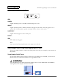

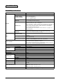
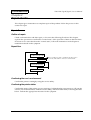
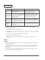
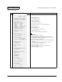
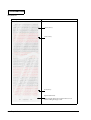


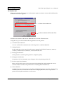

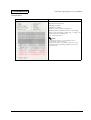


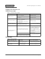
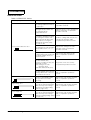
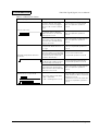


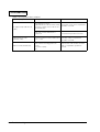
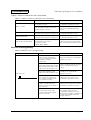
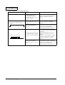
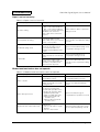
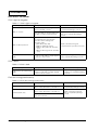


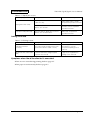

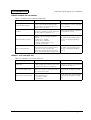

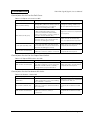


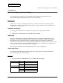


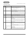
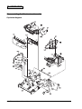
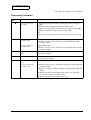

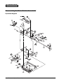
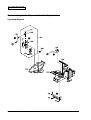

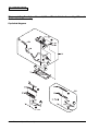
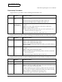
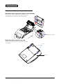
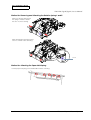
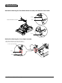
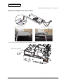
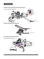
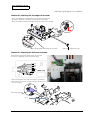


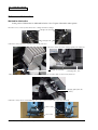


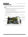
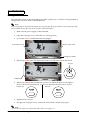
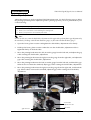

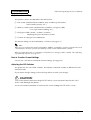
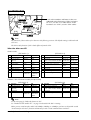
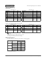
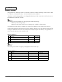
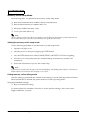
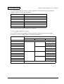
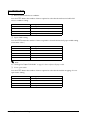

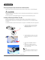
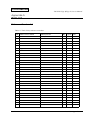

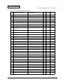
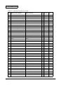
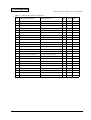

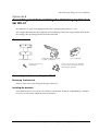
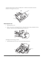


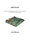

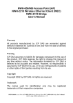
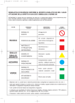


![[S3062PT-CPE-2] User`s Manual(First Edition): CPE62PSUE_2](http://vs1.manualzilla.com/store/data/005668190_1-0d028d6af383e5d06430420ca44dee4c-150x150.png)
![[S3062PT-CPE] User`s Manual(Third Edition): CPE62PUE](http://vs1.manualzilla.com/store/data/005693507_1-69a1045bbc5cf41449359b406d2a53f2-150x150.png)