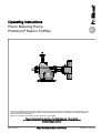
1
Operating instructions
Piston Metering Pump
ProMinent® Makro/ 5 M5Ka
ProMinent
Two sets of operating instructions are required for the safe, correct and proper operation of the metering pumps: The
product-specific operating instructions and the "General Operating Instructions for ProMinent® motor-driven metering
pumps and hydraulic accessories".
Both sets of operating instructions are only valid when read together.
Please carefully read these operating instructions before use! · Do not discard!
The operator shall be liable for any damage caused by installation or operating errors!
Technical changes reserved.
Part no. 985761
Original Operating Instructions (2006/42/EC)
BA MAK 007 10/11 EN
ProMinent Dosiertechnik GmbH
Im Schuhmachergewann 5-11
69123 Heidelberg
Germany
Telephone: +49 6221 842-0
Fax: +49 6221 842-617
email: [email protected]
Internet: www.prominent.com
985762, 1, en_GB
© 2010
2
Supplemental instructions
Supplementary information
Read the following supplementary information in its entirety! Should you
already know this information, you have an even greater need of the Oper‐
ating Instructions.
The following are highlighted separately in the document:
Fig. 1: Please read!
n
Enumerated lists
Instructions
ð Outcome of the handling instructions
- see (reference)
Information
This provides important information relating to the correct
operation of the device or is intended to make your work
easier.
Safety notes
Safety notes are identified by pictograms - see Safety Chapter.
General user instructions
Two sets of operating instructions are required for the safe, correct and
proper operation of the metering pumps: The product-specific operating
instructions and the "General Operating Instructions for ProMinent® motordriven metering pumps and hydraulic accessories".
Both sets of operating instructions are only valid when read together.
Please read these operating instructions carefully before use! Do not dis‐
card!
State the identity code and serial number
Please state identity code and serial number, which you can find on the
nameplate when you contact us or order spare parts. This enables the
device type and material versions to be clearly identified.
General non-discriminatory approach
In order to make it easier to read, this document uses the male form in
grammatical structures but with an implied neutral sense. It is aimed
equally at both men and women. We kindly ask female readers for their
understanding in this simplification of the text.
3
Table of contents
Table of contents
1
Identity code.................................................................................... 5
2
About this pump............................................................................... 7
3
Safety chapter................................................................................. 8
4
Storage, transport and unpacking................................................. 13
5
Overview of equipment, control elements..................................... 15
6
Functional description.................................................................... 18
7
Assembly....................................................................................... 20
8
Installation..................................................................................... 23
8.1 Installation, hydraulic............................................................. 23
8.2 Installation, electrical............................................................. 25
9
Start up.......................................................................................... 28
10
During use..................................................................................... 30
11
Maintenance.................................................................................. 31
12
Repairs.......................................................................................... 35
12.1 Changing the piston............................................................
12.2 Valve repair.........................................................................
12.2.1 Double ball valves............................................................
12.2.2 Single ball valves.............................................................
12.2.3 Plate valves......................................................................
36
40
41
42
42
13
Troubleshooting............................................................................. 44
14
Decommissioning and disposal..................................................... 46
14.1 Decommissioning................................................................ 46
14.2 Disposal.............................................................................. 48
15
Technical data............................................................................... 49
15.1 Performance data................................................................
15.2 Accuracy.............................................................................
15.2.1 Reproducibility..................................................................
15.2.2 Metering precision............................................................
15.3 Viscosity..............................................................................
15.4 Wetted materials.................................................................
15.5 Ambient conditions..............................................................
15.5.1 Temperatures...................................................................
15.5.2 Air humidity......................................................................
15.6 Housing degree of protection..............................................
15.7 Stroke sensor (option), intrinsically safe.............................
15.8 Filling volumes....................................................................
15.8.1 Gear oil.............................................................................
15.9 Sound pressure level..........................................................
15.10 Compatibility......................................................................
15.11 Supplement for modified versions.....................................
4
50
53
53
53
53
54
54
54
54
55
55
55
55
56
56
56
16
EC Declaration of Conformity........................................................ 57
17
Index.............................................................................................. 59
Identity code
1
M5Ka
Identity code
Makro/ 5 piston metering pumps
Power end type
H
Main power end
D
Main power end, doubled
A
Add-on power end
B
Add-on power end doubled
Type*
3200038
1400120 0500335 0250658 0121343
3200048
1400151 0500419 0250822 0121678
3200066
1400207 0500576 0251129 0122305
3200085
1270267 0450744 0231458 0122977
3200100
1000314 0350872 0181710 0103491
2400070
0800214 0350483 0160970 0062269
2400088
0800268 0350604 0161212 0062837
2400121
0800368 0350829 0161665 0063896
2160157
0700476 0301071 0162150 0065031
1700184
0560558 0251257 0162522 0066000
Dosing head material
SS
Stainless steel
Seal material
T
PTFE
Displacement body material
S
Stainless steel piston, chromium dioxide coated
Dosing head version
0
no valve spring
1
With valve spring
Hydraulic connector
0
Standard connection
4
Union nut and SS insert
Version
0
With ProMinent® logo, no frame
2
Without ProMinent® logo, no frame
A
With ProMinent® logo, with single frame
B
With ProMinent® logo, with double frame
C
With ProMinent® logo, with triple frame
D
With ProMinent® logo, with quadruple frame
M
Modified*
* order-related version, for pump fea‐
tures see order paperwork
Electric power supply
S
3 ph, 230 V/400 V 50/60 Hz (WBS)
5
Identity code
M5Ka
Makro/ 5 piston metering pumps
L
3 ph, 460 V, 60 Hz, (Exe, Exd)
P
3 ph, 230 V/400 V 50 Hz (Exe, Exd)
R
Variable speed motor 4 pole, 230/400 V (R 1:5)
N
1 ph, 115 V, 60Hz
V(0)
Motor with integral Frequency converter
V(2)
Motor with integral frequency converter (Exd)
5
No motor, with gear IEC 100
6
No motor, with gear IEC 112
0
No motor, no gear
Motor version
0
IP 55 (Standard) ISO class F
1
Exe version ATEX-T3
2
Exd version ATEX-T4
A
Power end ATEX design
Stroke sensor
0
No stroke sensor
1
Stroke sensor (Namur), intrinsically safe
Stroke length adjustment
0
Stroke length adjustment, manual
3
Control drive 230 V 0-20 mA
4
Control drive 230 V 4-20 mA
5
Control drive 115 V 0-20 mA
6
Control drive 115 V 4-20 mAz
Applications
0 standard
* Figure 1 - 3=back pressure [bar]; figure 4 - 7=flow rate [l/h]
6
About this pump
2
About this pump
All pumps
The ProMinent® Makro/ 5 piston metering pump is fitted as standard with a
3 kW wide range AC motor. The stroke length can be adjusted between
0...50 mm. The spheroidal graphite housing can be combined with up to
10 liquid end sizes and 5 gear reduction ratios (integrated in the spur
geared motor). The liquid ends are available in various material combina‐
tions which can be matched to the feed chemicals being metered.
Externally mounted pumps
The ProMinent® Makro/ 5 externally mounted metering pump can be com‐
bined with the Makro/ 5 main power end to form a double or multiple
pump. A main power end can be combined with up to four add-on power
ends. One power end can be used both as a single or a double head ver‐
sion.
Double head version
The double head versions are fitted with a second liquid end which oper‐
ates in push-pull mode (Boxer principle).
7
Safety chapter
3
Safety chapter
Identification of safety notes
Warning signs denoting different types of
danger
The following signal words are used in these operating instructions to
denote different severities of danger:
Signal word
Meaning
WARNING
Denotes a possibly dangerous sit‐
uation. If this is disregarded, you
are in a life-threatening situation
and this can result in serious inju‐
ries.
CAUTION
Denotes a possibly dangerous sit‐
uation. If this is disregarded, it
could result in slight or minor inju‐
ries or material damage.
The following warning signs are used in these operating instructions to
denote different types of danger:
Warning signs
Type of danger
Warning – hand injuries.
Warning – high-voltage.
Warning – flammable substances.
Warning – hot surface.
Warning – danger zone.
Correct and proper use
n
n
n
n
n
n
8
The pump may only be used to meter liquid metering chemicals.
In potentially explosive atmospheres in zone 1, device category II 2G
of explosion group II C, the pump must only be operated according to
the with the relevant nameplate (and the respective EC Declaration of
Conformity) for pumps for potentially explosive atmospheres com‐
plying with Directive 94/9/EC in accordance with the European guide‐
lines. The explosion group, category and degree of protection identi‐
fied on the marking must correspond with or be better than the given
conditions in the intended field of application.
The pump may only be started up after it has been correctly installed
and commissioned in accordance with the technical data and specifi‐
cations contained in the operating instructions.
The general limitations with regard to viscosity limits, chemical resist‐
ance and density must be observed - see also ProMinent resistance
list (In the product catalogue or at www.prominent.com)!
Any other uses or modifications are prohibited.
Pumps without the relevant nameplate (and the respective EC Decla‐
ration of Conformity) for pumps for potentially explosive atmospheres
must never be operated in potentially explosive atmospheres.
Safety chapter
n
n
n
n
n
The pump is not intended for the metering of gaseous media or solids.
The pump is not intended for unprotected outside use.
The pumps is not intended for the dosing of combustible fluids.
The pump should only be operated by trained and authorised per‐
sonnel, see also Ä ‘Qualification of personnel’ on page 9.
You are obliged to observe the information contained in the operating
instructions at the different phases of the device's service life.
In hazardous locations only the following combinations of identity code
variants is permitted:
Combi‐
nations
Identity code specification
values
1
Electric power supply
L, P
Motor version
1,2, V(2)
Stroke length adjustment
0, G, H
Electric power supply
0, 5.6
Motor version
A
Stroke length adjustment
0, G, H
2
Qualification of personnel
Activity
Qualification level
Storage, transport, unpacking
Instructed person
Assembly, installation of hydraulic
system
Technical personnel, service
Installation, electrical
Electrical technician
Operation
Instructed person
Maintenance, repair
Technical personnel, service
Decommissioning, disposal
Technical personnel, service
Troubleshooting
Technical personnel, electrical
technician, instructed person,
service
Explanation of the terms:
Technical personnel
A qualified employee is deemed to be a person who is able to assess the
tasks assigned to him and recognise possible dangers based on his/her
technical training, knowledge and experience, as well as knowledge of
pertinent regulations.
Note:
A qualification of equal validity to a technical qualification can also gained
by several years employment in the relevant work area.
Electrical technician
Electrical technicians are deemed to be people, who are able to complete
work on electrical systems and recognize and avoid possible dangers
independently based on their technical training and experience, as well as
knowledge of pertinent standards and regulations.
Electrical technicians should be specifically trained for the working envi‐
ronment in which the are employed and know the relevant standards and
regulations.
9
Safety chapter
Electrical technicians must comply with the provisions of the applicable
statutory directives on accident prevention.
Instructed person
An instructed person is deemed to be a person who has been instructed
and, if required, trained in the tasks assigned to him/her and possible dan‐
gers that could result from improper behaviour, as well as having been
instructed in the required protective equipment and protective measures.
Service
Customer Service department refers to service technicians, who have
received proven training and have been authorised by ProMinent or Pro‐
Maqua to work on the system.
Safety notes
WARNING!
Warning of dangerous or unknown feed chemical
Should a dangerous or unknown feed chemical be used: It
may escape from the hydraulic components when working
on the pump.
–
–
Take appropriate protective measures before working on
the pump (e.g. safety glasses, safety gloves, ...).
Observe the safety data sheet for the feed chemical.
Drain and flush the liquid end before working on the
pump.
WARNING!
Danger from hazardous substances!
Possible consequence: Fatal or very serious injuries.
Please ensure when handling hazardous substances that
you have read the latest safety data sheets provided by the
manufacture of the hazardous substance. The actions
required are described in the safety data sheet. Check the
safety data sheet regularly and replace, if necessary, as the
hazard potential of a substance can be re-evaluated at any
time based on new findings.
The system operator is responsible for ensuring that these
safety data sheets are available and that they are kept up to
date, as well as for producing an associated hazard assess‐
ment for the workstations affected.
CAUTION!
Warning of feed chemical spraying around
Feed chemical can spray out of the hydraulic components if
they are manipulated or opened due to pressure in the liquid
end and adjacent parts of the system.
–
–
10
Disconnect the pump from the mains power supply and
ensure that it cannot be switched on again by unauthor‐
ised persons.
Depressurise the system before commencing any work
on hydraulic parts.
Safety chapter
CAUTION!
Warning of feed chemical spraying around
An unsuitable feed chemical can damage the parts of the
pump contacted by the chemical.
–
Take into account the resistance of the materials which
will come into contact with the chemical when selecting
the feed chemical - see the ProMinent product catalogue
or under www.prominent.com.
CAUTION!
Danger of personnel injury and material damage
The use of untested third party parts can result in personnel
injuries and material damage.
–
Only fit parts to metering pumps, which have been
tested and recommended by ProMinent.
CAUTION!
Danger from incorrectly operated or inadequately maintained
pumps
Danger can arise from a poorly accessible pump due to
incorrect operation and poor maintenance.
–
–
Ensure that the pump is accessible at all times.
Adhere to the maintenance intervals.
CAUTION!
Warning of illegal operation
Observe the regulations that apply where the unit is to be
installed.
Information in the event of an emergency
In the event of an electrical accident, disconnect the mains cable from the
mains or press the emergency cut-off switch fitted on the side of the
system!
If feed chemical escapes, also depressurise the hydraulic system around
the pump as necessary. Adhere to the safety data sheet for the feed
chemical.
11
Safety chapter
Protective equipment
6
1
2
3
4
5
P_MAK_0025_SW
Fig. 2: Isolating protective equipment Makro/ 5 with add-on power end
(shown here for piston version)
1
2
3
4
5
6
Cap (only single head version)
Fan impeller hood
Terminal box cover, motor
Cover plate (only with add-on power end)
Flange cover
Protective cover (only diaphragm and piston versions)
WARNING!
Warning of personal injury and material damage
– The customer must only remove the protective equip‐
ment if requested to do so by the operating instructions.
– The pump must not operate without fitted protective
equipment.
Sound pressure level
Sound pressure level LpA < 75 dB in accordance with EN ISO
20361:2010-10
at maximum stroke length, maximum stroke rate, maximum back pressure
(water)
12
Storage, transport and unpacking
4
Storage, transport and unpacking
Safety notes
WARNING!
The transporting of pumps which have been used with radio‐
active feed chemicals is forbidden!
They will also not be accepted by ProMinent!
WARNING!
Only return metering pumps for repair in a cleaned state and
with a flushed liquid end - refer to the section on decommis‐
sioning!
Only send metering pumps with a filled in Decontamination
Declaration form. The Decontamination Declaration consti‐
tutes an integral part of an inspection / repair order. A unit
can only be inspected or repaired when a Declaration of
Decontamination Form is submitted that has been completed
correctly and in full by an authorised and qualified person on
behalf of the pump operator.
You can find the "Decontamination Declaration" form under
www.prominent.com or on the CD.
CAUTION!
Danger of environmental and material damage
The unit can be damaged or oil may escape due to incorrect
or improper storage or transportation!
–
–
–
–
Scope of supply
Compare the delivery note with the scope of supply:
n
n
n
n
n
Storage
The unit should only be stored or transported in a well
packaged state - preferably in its original packaging.
Only transport the unit with the locking screw - not the
bleed plug - fitted to the oil filling opening.
The packaged unit should also only be stored or trans‐
ported in accordance with the stipulated storage condi‐
tions.
The packaged unit should be protected from moisture
and the ingress of chemicals.
Metering pump with mains power cable
Connector kit for tube/pipe connection
Product-specific operating instructions with EC Declaration of Con‐
formity
CD with order information, exploded diagrams, performance diagrams,
motor data sheet and dimension sheets
Optional accessories if ordered
Personnel:
n
Technical personnel
1.
Place the caps on the valves.
2.
Check whether the seal screw is screwed into oil filler opening
instead of the vent screw.
3.
Preferably place the pump standing vertically on a pallet and secure
against falling over.
4.
Cover the pump with a tarpaulin cover - allowing rear ventilation.
13
Storage, transport and unpacking
Store the pump in a dry, sealed place in the following ambient conditions.
Ambient conditions
Data
Minimum storage and transport tempera‐
ture
-10 °C
Maximum storage and transport tempera‐
ture
+50 °C
Maximum air humidity *
* non-condensing
14
Value Unit
95 % rel.
humidity
Overview of equipment, control elements
5
Overview of equipment, control elements
Power end, single head
2
3
1
1
4
P_MAK_0027_SW
5
C
A
Fig. 3: View from the motor side (here M5Ka H)
A
C
1
2
3
4
5
Power end
Liquid end
Lifting eye
Stroke length adjustment wheel
Indicating dial
motor
Oil drain plug
6
7
P_MAK_0027_SW
Fig. 4: View away from the motor (here M5Ka H)
6
7
Vent screw
Oil inspection window
15
Overview of equipment, control elements
Power end, double head
2
3
1
1
4
P_MAK_0029_SW
5
C
A
C
Fig. 5: View from the motor side (here M5Ka D)
A
C
1
2
3
4
5
Power end
Liquid end
Lifting eye
Stroke length adjustment wheel
Indicating dial
motor
Oil drain plug
6
7
P_MAK_0030_SW
Fig. 6: View away from the motor (here M5Ka D)
6
7
16
Vent screw
Oil inspection window
Overview of equipment, control elements
Liquid end
6
5
1
2
4
3
P_MAK_0034_SW
Fig. 7
1
2
3
4
5
6
Discharge valve
Dosing head
Suction valve
Support bracket
Protective cover
Tube nozzles for leakage/flushing connector
17
Functional description
6
Functional description
Power end functional description
The Makro/ 5 metering pump is a motor-driven metering pump with a kine‐
matic gear.
A motor drives the cam shaft (1). A connecting rod (2) rests on the cam
shaft (1) which allows the oscillating crank (4) to rotate about a variable
pivot point, see Fig. 8. The lifting arm of the oscillating crank, which lies
above the pivot point, moves the slide rod (8) which itself drives the liquid
end.
The stroke is adjusted using the manual adjustment wheel (7). This
causes a spindle (6) to move the fork (5; shown in cutaway view in the dia‐
gram). The fork (5) moves the sliding block (3) in a groove cut into the
oscillating crank (4). The sliding block (3) determines the pivot point of the
oscillating crank (4). This determines the stroke length. When the pivot
point of the sliding block (3) is directly above the axle of the slide rod (8)
the lifting arm of the oscillating crank above the pivot point is at zero and
the slide rod stops. When the sliding block (3) is pushed down, the lifting
arm of the oscillating crank (4) above the pivot point is greater than zero
so that the slide rod (8) is driven
Liquid ends can be fitted to both ends of the slide rod. They then operate
in push-pull mode (Boxer principle).
7
6
5
8
4
3
2
1
P_MAK_0035_SW
Fig. 8: Cross-section through the power end
1
2
3
4
5
6
7
8
Functional description of the piston liquid
end (for M5Ka)
18
Cam shaft
Connecting rod
Sliding block
Oscillating crank
Fork
Spindle
Manual adjustment wheel
Slide rod
The heart of the liquid end is a highly resistant piston (2) made from
coated stainless steel. The suction valve (5) closes as soon as the piston
(2) is moved in to the dosing head and the feed chemical flows through the
discharge valve (1) out of the dosing head. The discharge valve (1) closes
as soon as the piston moves in the opposite direction due to the vacuum
pressure in the dosing head and fresh feed chemical flows through the
suction valve (5) into the dosing head. The flushing collar (3) can be used
to flush the sealing surfaces of the piston or lead-off leakage liquid.
Functional description
1
2
3
4
5
P_MAK_0039_SW
Fig. 9: Cross-section through the liquid end
1
2
3
4
5
Discharge valve
Piston
Flushing collar
Packing collar
Suction valve
19
Assembly
7
Assembly
Safety notes
WARNING!
Warning about personal and material damage
EX pumps only: When operating in EX areas, certain sub‐
jects must be observed.
–
The chapter "Important supplements for metering pumps
in EX zones" of the "General Operating Instructions on
ProMinent ® Motor-Driven Metering Pumps and Hydraulic
Accessories" must be observed in all cases.
CAUTION!
Warning about personal and material damage
Also observe the "General Operating Instructions for ProMi‐
nent ® Motor-Driven Metering Pumps and Hydraulic Accesso‐
ries"!
CAUTION!
Danger of environmental and material damage
The unit can be damaged or oil may escape due to incorrect
or improper storage or transportation!
–
–
–
–
The unit should only be stored or transported in a well
packaged state - preferably in its original packaging.
Only transport the unit with the locking screw - not the
bleed plug - fitted to the oil filling opening.
The packaged unit should also only be stored or trans‐
ported in accordance with the stipulated storage condi‐
tions.
The packaged unit should be protected from moisture
and the ingress of chemicals.
CAUTION!
Warning about personal and material damage
Personal and material damage may be caused if the unit is
operated outside of the permissible ambient conditions.
–
Please observe the permissible ambient conditions refer to the chapter entitled "Technical Data".
Supporting floor
WARNING!
Risk of electric shock
If water or other electrically conducting liquids penetrate into
the drive housing, an electric shock may occur.
–
h
P_MOZ_0016_SW
Fig. 10
20
Position the pump so that drive housing cannot be
flooded.
Assembly
WARNING!
The pump can break through the supporting floor or slide off
it
– The supporting floor must be horizontal, smooth and per‐
manently load-bearing.
Capacity too low
Vibrations can disturb the valves of the liquid end.
–
The supporting floor must not vibrate.
Space requirement
CAUTION!
Danger from incorrectly operated or inadequately maintained
pumps
Danger can arise from a poorly accessible pump due to
incorrect operation and poor maintenance.
A
–
–
A
Ensure that the pump is accessible at all times.
Adhere to the maintenance intervals.
Position the pump so that control elements such as the stroke length
adjustment knob, the indicating dial A or the oil inspection window are
accessible.
P_MOZ_0018_SW
Fig. 11
In so doing, ensure there is enough space to carry out an oil change (vent
screws, oil drain plugs, oil trough ...).
f
1
2
f
f
1
2
3
Discharge valve
Dosing head
Suction valve
Ensure there is sufficient free space (f) around the dosing head as well as
the suction and discharge valve so that maintenance and repair work can
be carried out on these components.
3
P_MOZ_0017_SW
Fig. 12
Liquid end alignment
Capacity too low
If the valves of the liquid end do not stand upright, they
cannot close correctly.
–
The discharge valve must be upright.
Fastening
Capacity too low
Vibrations can disturb the valves of the liquid end.
–
Secure the metering pump so that no vibrations can
occur.
21
Assembly
m
DN
Take the dimensions (m) for the fastening holes from the appropriate
dimensional drawings or data sheets.
Fasten the pump base to the supporting floor using suitable screws.
m
P_MOZ_0015_SW
Fig. 13
Instruction
Screw the pump to a support surface with 4 sufficiently strong
screws through the 4 holes in the frame.
Nothing more need be fitted to the pump itself: the pump is filled with gear
oil and completely assembled on a frame.
22
Installation
8
Installation
CAUTION!
Danger of personnel injury and material damage
The disregard of technical data during installation may lead
to personal injuries or damage to property.
–
Observe the technical data- refer to chapter "Technical
Data" and, where applicable, the operating instructions
of the accessories.
8.1 Installation, hydraulic
WARNING!
Warning about personal and material damage
EX pumps only: When operating in EX areas, certain sub‐
jects must be observed.
–
The chapter "Important supplements for metering pumps
in EX zones" of the "General Operating Instructions on
ProMinent ® Motor-Driven Metering Pumps and Hydraulic
Accessories" must be observed in all cases.
WARNING!
Warning of feed chemical reactions to water
Feed chemicals that should not come into contact with water
may react to residual water in the liquid end that may origi‐
nate from works testing.
–
–
Blow the liquid end dry with compressed air through the
suction connector.
Then flush the liquid end with a suitable medium through
the suction connector.
WARNING!
The following measures are an advantage when working with
highly aggressive or hazardous feed chemicals:
–
–
Install a bleed valve with recirculation in the storage
tank.
Install an additional shut-off valve on the discharge or
suction ends.
CAUTION!
Warning about personal and material damage
Also observe the "General Operating Instructions for ProMi‐
nent ® Motor-Driven Metering Pumps and Hydraulic Accesso‐
ries"!
23
Installation
CAUTION!
Suction problems possible
For feed chemicals with a particle size greater than 0.3 mm,
the valves may no longer close properly.
–
Install a suitable filter in the suction line.
CAUTION!
Warning against the discharge line bursting
With a closed discharge line (e.g. due to a clogged discharge
line or by closing a valve), the pressure that the metering
pump generates can reach several times the permissible
pressure of the system or the metering pump. This could
lead to lines bursting resulting in dangerous consequences
with aggressive or toxic feed chemicals.
–
Install a relief valve that limits the pressure of the pump
to the maximum permissible operating pressure of the
system.
CAUTION!
Warning against the discharge line bursting
Tube lines with insufficient pressure rating may burst.
–
Only use tube lines with the required pressure rating.
CAUTION!
Warning against lines disconnecting
With suction, discharge and relief lines installed incorrectly
can loosen / disconnect from the pump connection.
–
–
–
–
–
Personnel:
Route the leakage liquid drainage line
24
Only use original tubing with the specified tube diameter
and wall thickness.
Only use clamp rings and tube nozzles that correspond
with the respective hose diameter.
Always connect the lines without mechanical tension.
Precise metering is only possible when the back pres‐
sure is maintained above 1 bar at all times.
If metering at atmospheric pressure, a back pressure
valve should be used to create a back pressure of
approx. 1.5 bar.
n
Technical personnel
The leakage liquid is drained off via the flushing collar and a tube nozzle,
without other parts of the liquid end coming into contact with the medium.
1.
Connect a tube to the lower tube nozzle.
2.
Route the tube into a collection device for the leakage liquid.
Installation
8.2 Installation, electrical
WARNING!
Danger of electric shock
Unprofessional installation may lead to electric shocks.
–
–
All cable cores cut to length must be provided with cable
end sleeves.
The Installation, electrical of the device may only be
undertaken by technically trained personnel.
WARNING!
Danger of electric shock
In the event of an electrical accident, it must be possible to
quickly disconnect the pump, and any electrical ancillaries
which may possibly be present, from the mains.
–
–
Install an emergency cut-off switch in the mains supply
line to the pump and any electrical ancillaries which may
be present or
Integrate the pump and electrical ancillaries which may
be present in the emergency cut-off management of the
system and inform personnel of the isolating option.
WARNING!
Danger of electric shock
This pump is equipped with a protective earth conductor, to
reduce the risk arising from an electric shock.
–
Connect the PE conductor to "earth" with a clean and
permanent electrical connection.
WARNING!
Danger of electric shock
A mains voltage may exist inside the pump housing.
–
If the pump housing has been damaged, you must dis‐
connect it from the mains immediately. It may only be
returned to service after an authorised repair.
WARNING!
Warning about personal and material damage
EX pumps only: When operating in EX areas, certain sub‐
jects must be observed.
–
The chapter "Important supplements for metering pumps
in EX zones" of the "General Operating Instructions on
ProMinent ® Motor-Driven Metering Pumps and Hydraulic
Accessories" must be observed in all cases.
CAUTION!
Warning about personal and material damage
Also observe the "General Operating Instructions for ProMi‐
nent ® Motor-Driven Metering Pumps and Hydraulic Accesso‐
ries"!
25
Installation
Personnel:
n
Electrician
What requires electrical installation?
n
n
n
n
n
n
motor
External fan (option)
Stroke control drive (Option)
Stroke adjusting drive (Option)
Stroke sensor (Option)
Frequency converter (option)
motor
CAUTION!
Pump can be damaged
The pump can be damaged if the motor drives the pump in
the wrong direction.
–
When connecting the motor, pay attention to the correct
direction of rotation indicated by the arrow on the fan
cover, as shown in Fig. 14.
CAUTION!
The motor may be damaged
The motor is not equipped with a fuse.
–
Install a suitable motor protection switch.
P_SI_0012_SW
Fig. 14: Direction of rotation of motor
1.
Use a suitable cable between the motor terminal box and power
supply.
2.
Install an emergency cut-off switch or include the motor in the emer‐
gency cut-off management of the system.
–
–
–
–
26
Key motor data can be found on the unit nameplate.
Motor data sheets can be requested for more informa‐
tion.
The terminal wiring diagram is located in the terminal
box.
Notes on the speed controlled motor with external fan
and temperature monitoring can be found in the "Gen‐
eral operating instructions for ProMinent® motor-driven
metering pumps and hydraulic accessories"!
Installation
The external fan requires an independent mains connection.
Stroke sensor (Option)
Connect the stroke sensor to a suitable monitoring device according
to the details in the chapter "Technical Data". Also observe its tech‐
nical data.
Other units
Install the other units according to their documentation.
27
Start up
9
Start up
Safety notes
WARNING!
Warning about personal and material damage
EX pumps only: When operating in EX areas, certain sub‐
jects must be observed.
–
The chapter "Important supplements for metering pumps
in EX zones" of the "General Operating Instructions on
ProMinent ® Motor-Driven Metering Pumps and Hydraulic
Accessories" must be observed in all cases.
WARNING!
Hot surface
In event the power end motor is loaded excessively, its sur‐
face may become very hot.
–
–
Avoid contact.
If necessary, mount a guard plate.
CAUTION!
Possible environmental and material damage
The screw plug in the oil filler neck is factory-fitted and,
during operation, prevents any pressure equalisation
between the power end housing and the surroundings. This
ensure that oil can be pushed from the power end housing.
–
–
Replace the screw plug on the oil filler neck by the air
vent plug supplied.
Retain the sealing plug for subsequent transport of the
unit.
CAUTION!
Single head version only: Oil may escape
The screw plug in the oil filler neck is factory-fitted and,
during operation, prevents any pressure equalisation
between the power end housing and the surroundings. This
ensure that oil can be pushed from the power end housing.
–
Ensure that the hole in the metal cap on the drive flange
is always clear - see "Overview of equipment, control
elements".
CAUTION!
Warning about personal and material damage
Also observe the "General Operating Instructions for ProMi‐
nent ® Motor-Driven Metering Pumps and Hydraulic Accesso‐
ries"!
CAUTION!
Liquid end may be damaged
– For feed chemicals with a particle size greater than 0.3
mm, always fit a filter in the suction line
28
Start up
Installing a vent screw
Replace the sealing screw at the oil filler neck with the supplied vent screw
- see chapter "Overview of equipment and control elements".
Checking the oil level
When the pump is idle, check whether the pump oil level slightly covers
the lower oil inspection window.
This indicates that the pump has not lost oil and consequently been dam‐
aged.
Checking the direction of rotation
When commissioning the unit, check whether the drive motor is rotating
correctly - check this against the arrow on the motor housing or the dia‐
gram in the chapter entitled "Electrical Installation."
Eliminating suction problems (only for single ball valves with
PTFE ball seat)
For suction problems occurring during start up:
–
–
–
–
Exclude the possibility that there are foreign bodies in
the valve.
Place the valve on a stable surface.
Using a hammer (1) and a brass bar (2), gently tap the
PTFE ball seat above the valve ball - see figure below.
Then with the valve in a damp condition allow it to prime.
Fig. 15: Tapping the valve set disc
Adjusting the stroke length
Only adjust the stroke length when the pump is running. This
is easier and also better for the pump.
Correctly adjusting the pump:
n
n
n
n
Checking the leakage
Select as large a stroke length as possible for viscous feed chemicals.
Select as large a stroke length as possible for outgassing feed chemi‐
cals.
Select as high a stroke rate as possible for good mixing.
For precise metering using quantity-proportional metering, do not set
the stroke length to less than 30 %.
Check whether the leakage for the feed chemical used is between 10 and
120 drops /min.
The pump can now be released for operation.
29
During use
10
During use
WARNING!
Warning about personal and material damage
EX pumps only: When operating in EX areas, certain sub‐
jects must be observed.
–
The chapter "Important supplements for metering pumps
in EX zones" of the "General Operating Instructions on
ProMinent ® Motor-Driven Metering Pumps and Hydraulic
Accessories" must be observed in all cases.
WARNING!
Personnel injury and material damage may occur
During use all units, protective equipment, additional devices
must be fitted, operational and tightly closed.
WARNING!
Hot surface
In event the power end motor is loaded excessively, its sur‐
face may become very hot.
–
–
Avoid contact.
If necessary, mount a guard plate.
WARNING!
Sparking caused by dry running
If the bearings in the power end run dry, sparks can be
formed.
–
–
Check for oil leaks.
When the pump is idle, the pump oil level must slightly
cover the lower oil inspection window.
Observe the instructions in the "Start up" chapter and the
operating instructions for the other machine components.
30
Maintenance
11
Maintenance
Safety notes
WARNING!
Warning about personal and material damage
EX pumps only: When operating in EX areas, certain sub‐
jects must be observed.
–
The chapter "Important supplements for metering pumps
in EX zones" of the "General Operating Instructions on
ProMinent ® Motor-Driven Metering Pumps and Hydraulic
Accessories" must be observed in all cases.
WARNING!
It is mandatory that you read the safety information and
specifications in the "Storage, Transport and Unpacking"
chapter prior to shipping the pump.
WARNING!
Hot surface
In event the power end motor is loaded excessively, its sur‐
face may become very hot.
–
–
Avoid contact.
If necessary, mount a guard plate.
WARNING!
Warning of hazardous or unknown feed chemical
Should a hazardous or unknown feed chemical be used, it
may escape from the hydraulic components when working
on the pump.
–
–
Take appropriate protective measures before working on
the pump (protective eyewear, protective gloves, ...).
Read the safety data sheet on the feed chemical.
Drain and flush the liquid end before working on the
pump.
WARNING!
Risk of fingers being crushed
Under unfavourable conditions, the stroke axle or displace‐
ment body can cause crushing of the fingers.
–
Disconnect the pump from the mains power supply and
ensure that it cannot be switched on again by unauthor‐
ised persons.
WARNING!
Risk of injury from the fan impeller
The fan impeller beneath motor's fan cowling can cause
severe injuries while it is turning.
–
The pump must only be connected to the mains voltage
with the fan cowling closed.
31
Maintenance
CAUTION!
Warning of feed chemical spraying around
Feed chemical can spray out of the hydraulic components if
they are manipulated or opened due to pressure in the liquid
end and adjacent parts of the system.
–
–
Disconnect the pump from the mains power supply and
ensure that it cannot be switched on again by unauthor‐
ised persons.
Depressurise the system before commencing any work
on hydraulic parts.
Maintenance work
Under heavy loading (e.g. continuous operation) shorter
maintenance intervals are recommended than those given.
Keep a spare parts kit in stock ready for maintenance work.
Order numbers are contained on the CD.
Interval
Maintenance work
Quarterly*
EX pumps only: For special maintenance work see chapter "Important supplements for metering
pumps in hazardous locations" of the "General Operating Instructions for ProMinent® motor-driven
metering pumps and hydraulic accessories"
Check the starting torque torques for the dosing head flange screws (1) (24 Nm) and the turret flange
screws (2) (19 Nm).
Check that the discharge valve and suction valve are correctly seated.
Check the correct seating and state of the metering lines at both discharge and suction ends.
Check the tightness of the entire liquid end - particularly around the leakage hole!
Check the oil level.
Single head versions only: Check that the hole in the metal cap on the drive flange is clear - see the
figure in the "Safety Chapter".
Check that the electrical connections are intact
Check whether the pump is transporting media correctly - run briefly at high power. Observe the max‐
imum permissible operating pressure!
Check whether the leakage level is OK: 10 ... 120 drops / min.
32
Maintenance
1
(24 Nm)
2
(19 Nm)
P_MAK_0042_SW
Fig. 16: Liquid end torques
1
2
Dosing head screws
Turret flange screws
Interval
Maintenance work
After approx. 5,000 operating hours
Change the gear oil.
* Under normal loading (approx. 30 % of continuous operation)
Under heavy loading (e.g. continuous operation): Shorter intervals.
Changing the gear oil
WARNING!
Risk of burns due to hot gear oil
The gear oil may become very hot when the pump is heavily
loaded
–
When draining oil, avoid contact with the oil running out.
Gear oil
Gear oil
Supplied quantity
Mobilgear 634 VG 460
Part no.
20.0 l
1006284
Gear oil filling volumes
Types
Volume, approx.
All
16.5 l
Draining the gear oil:
1.
Remove the vent screw (1).
2.
Place an oil trough under the oil drain plug (2). Expected oil quantity
- see filling volumes, above.
3.
Unscrew the oil drain plug (2) out of the power end housing.
4.
Allow the gear oil to run out of the power end.
5.
Screw in the oil drain plug (2) with a new seal.
33
Maintenance
1
P_MAK_0043_SW
2
Fig. 17: Oil change 1
1
2
Vent screw
Oil drain plug
Filling with gear oil:
1.
Start the pump.
2.
Slowly pour gear oil through the vent screw (1) opening until the
upper oil inspection window (3) is slightly covered.
3.
Allow the pump to run for a further 1... 2 minutes.
4.
Replace the vent screw (1).
3
P_MAK_0044_SW
Fig. 18: Oil change 2
3
34
Oil inspection windows
Repairs
12
Repairs
Safety notes
WARNING!
Warning about personal and material damage
EX pumps only: When operating in EX areas, certain sub‐
jects must be observed.
–
The chapter "Important supplements for metering pumps
in EX zones" of the "General Operating Instructions on
ProMinent ® Motor-Driven Metering Pumps and Hydraulic
Accessories" must be observed in all cases.
WARNING!
It is mandatory that you read the safety information and
specifications in the "Storage, Transport and Unpacking"
chapter prior to shipping the pump.
WARNING!
Hot surface
In event the power end motor is loaded excessively, its sur‐
face may become very hot.
–
–
Avoid contact.
If necessary, mount a guard plate.
WARNING!
Warning of hazardous or unknown feed chemical
Should a hazardous or unknown feed chemical be used, it
may escape from the hydraulic components when working
on the pump.
–
–
Take appropriate protective measures before working on
the pump (protective eyewear, protective gloves, ...).
Read the safety data sheet on the feed chemical.
Drain and flush the liquid end before working on the
pump.
WARNING!
Risk of fingers being crushed
Under unfavourable conditions, the stroke axle or displace‐
ment body can cause crushing of the fingers.
–
Disconnect the pump from the mains power supply and
ensure that it cannot be switched on again by unauthor‐
ised persons.
WARNING!
Risk of injury from the fan impeller
The fan impeller beneath motor's fan cowling can cause
severe injuries while it is turning.
–
The pump must only be connected to the mains voltage
with the fan cowling closed.
35
Repairs
CAUTION!
Warning of feed chemical spraying around
Feed chemical can spray out of the hydraulic components if
they are manipulated or opened due to pressure in the liquid
end and adjacent parts of the system.
–
–
12.1
Disconnect the pump from the mains power supply and
ensure that it cannot be switched on again by unauthor‐
ised persons.
Depressurise the system before commencing any work
on hydraulic parts.
Changing the piston
WARNING!
Observe the safety notes at the beginning of the chapter.
Removing the liquid end
1.
Flush the suction line, discharge lines and liquid end (activate
flushing equipment or immerse suction lance in a suitable medium
and pump for a while (consider the effect of the medium on your
system first!)) or proceed, as described below.
2.
Set the stroke length to 0 % stroke with the pump running.
3.
Switch off the pump.
4.
Secure the pump to prevent it being switched back on.
5.
If the liquid end has not been flushed according to the above pro‐
cesses, then protect yourself against the feed chemical - protective
clothing, safety glasses, ... .
After dismantling immediately place parts that have been wetting
with the medium in a trough with a suitable medium for flushing, in
dangerous media were used flush and rinse thoroughly.
6.
Unscrew the hydraulic connectors on the discharge and suction
side.
7.
Remove the protective cover (4) from the turret - see Fig. 19.
8.
Remove a safety collar (2) from the bolt at the swivel head and pull
out the bolt (1)
9.
Place a sling around the liquid end and suspend from a crane.
WARNING!
Heavy parts may fall
– A helper must steady the liquid end by hand.
– Secure the piston to prevent it falling out.
36
10.
If available: Remove the leakage or flushing tubes from the tube
nozzles (6).
11.
If available: Unscrew the support bracket (5) from the liquid end.
12.
Remove the securing screws (3) from the turret flange
13.
Remove the liquid end and place onto a solid, even surface
Repairs
1 2
6
3
4
5
P_MAK_0048_SW
Fig. 19: View of the liquid end
1
2
3
4
5
6
Bolt
Safety collar
Securing screws
Protective cover
Support bracket (option)
Tube nozzles for leakage/flushing connector
Repairing the liquid end
1
8
2
7 654
3
P_MAK_0049_SW
Fig. 20: Cross-section through the liquid end
1
2
3
4
5
6
7
8
Piston
Tube nozzle
Tensioning screw
Dosing head flange
Guide bands
Guide sleeves
Flushing collar
Packing collars
1.
Loosen the tensioning screw (3) using the face spanner and remove
- see Fig. 20.
2.
Loosen the dosing head flange (4) screws and remove the dosing
head flange.
37
Repairs
3.
Remove the piston (1)
Now record the sequence of parts as your remove them
ready for the reassembly.
5.
Remove the guide sleeves (6) and guide bands (5), the packing col‐
lars (8) and flushing collar (7).
6.
Thoroughly clean the sealing area
7.
Clean the piston (1), the guide sleeves (6) and the flushing collar (7)
8.
Dispose of the packing collars and guide bands
9.
Insert the piston (1)
Now reassemble the parts using a reverse sequence of steps:
1.
Have new packing collars ready.
CAUTION!
The piston may be damaged
– Never push the packing collars on with a sharp object.
2.
Evenly push in the guide sleeve (6) with a new guide band and a
packing collar.
3.
Insert the other packing collars with the cut ends alternately rotated
through 180°.
4.
Sequentially insert the flushing collar (7), two further packing collars
and the guide sleeve (6) with a new guide band into the sealing
area
5.
Place the dosing head flange (4) on the liquid end and tighten.
Tightening torque
24 Nm
CAUTION!
The piston may be damaged
– Only lightly tighten the tensioning screw.
6.
Position the tensioning screw and only hand-tighten.
1.
Place a sling around the liquid end and suspend from a crane.
Fitting the liquid end
WARNING!
Heavy parts may fall
– A helper must steady the liquid end by hand.
– Secure the piston to prevent it falling out.
2.
Place the liquid end on the drive flange and secure using the
retaining screws.
Tightening torque
38
19 Nm
Repairs
Positioning the liquid end
1.
Align the holes of the swivel head and fork head - see Fig. 20.
2.
Push the bolt through the holes and insert the safety collar in the
bolt.
3.
Clamp the protective cover over the turret.
4.
If available: Screw the support bracket onto the liquid end.
5.
If available: Fit the leakage or flushing tubes on to the tube nozzles.
Installing of packing collars
Correct pressure of the tensioning screw
Packing collars should limit, not prevent, the escaping of
feed chemical. Leakage is necessary to reduce the friction
and dissipate the resulting friction heat.
In Fig. 21 the feed chemical presses from the left through the
packing collar a (drop on the right!). The tensioning screw A
presses on the packing collar from the right.
a
B
A
b
P_MAK_0050_SW
Fig. 21: Correct pressure of the tensioning screw
a
b
A
B
Packing collar
Piston
Tensioning screw pressure
Feed chemical pressure
Allow the pump to run for the first 10 ... 15 min with this leakage rate:
Leakage in the first 10 ... 15 min
50 ... 200 drops / min
Then:
1.
Stop the pump.
2.
Remove the protective cover.
3.
Carefully tighten the tensioning screw.
4.
Clamp the protective cover over the turret.
5.
Start the pump.
6.
Check the leakage.
Repeat steps 1. – 6. until minimum leakage is achieved:
Minimum leakage
10 ... 120 drops / min
39
Repairs
The minimum leakage is dependent on the feed chemical,
the feed chemical pressure, the temperature and the piston
speed.
CAUTION!
The piston may be damaged
If the tensioning screw pressure is too high, dry running can
occur and then damage to the piston and the packing collars.
–
Do not overtighten the tensioning screw.
The result of too high tensioning screw pressure
The feed chemical can no longer press though the packing
collars - liquid lubrication is prevented. The piston runs dry.
As a result the packing collars are scorched/burnt and the
piston damaged. Leakage increases greatly.
a
B
A
b
P_MAK_0051_SW
Fig. 22: The result of too high tensioning screw pressure
a
b
A
B
12.2
Packing collar
Piston
Tensioning screw pressure
Feed chemical pressure
Valve repair
Unsuitable spare parts for the valves may lead to problems
for the pumps.
–
–
Only use new components that are especially adapted to
fit your valve (both in terms of shape and chemical
resistance).
Use the correct spare part kits. In case of doubt, refer to
the exploded views and ordering information contained
in the "Supplementary information CD for ProMinent®
pump operating instructions".
Clean the discharge and suction valves only one after
another as they cannot be differentiated using the arrow
markings.
40
Repairs
12.2.1
Double ball valves
Cleaning a discharge valve
Taking the discharge valve apart
1.
Unscrew the discharge valve from the dosing head and rinse out.
2.
Dismantle the discharge valve.
3.
Rinse and clean all parts.
4.
Replace the worn parts and seals.
Assembling the discharge valve
When assembling, take note of the orientation of the valve
seats (3). The valve seats (3) are used as a ball seat on the
fine machined side and as a ball cage and spring guide on
the other side. The fine machined side must point in the flow
direction with all valve seats.
When assembling the valves, take note of the sequence:
Teflon – Metal – Teflon – Metal - ...
1.
Slide into the valve body (1) one after another:
n
n
n
n
n
n
n
1
2
3
4
*
n
n
5
2.
one seal (2) and one valve seat (3) - correct!
one seal (2) and one valve bushing (4)
(If fitted: one spring (*) into the spring guide of the valve seat (3)
one ball (5) into the valve body (1)
one seal (2) and the second valve seat (3, correct!)
one seal (2) and the second valve bushing (4)
(If fitted: the second spring (*) into the spring guide of the valve
seat (3))
the second ball (5) into the valve body (1)
one seal (2), the third valve seat (3) - (correct!) and a further
seal (2)
Position the insert disc (6) with the flare on the packing.
The distance between the edge of the valve body and
the insert disk (6) is due to the construction.
*
3.
Place the larger seal (7) between the insert disk (6) and the dosing
head.
4.
Screw in the valve until the stop.
6
7
Fig. 23: Discharge valve (double ball
valve).
Cleaning a suction valve
A suction valve is dismantled, cleaned and assembled in the same way as
a discharge valve.
Please note, however, that when assembling, the valve seat
(3) must be aligned in the other direction. The fine machined
side must point in the flow direction with all valve seats (3).
41
Repairs
12.2.2
Single ball valves
1.
Screw the valve cap (5) on to the suction side - see .
2.
Carefully remove the parts from the valve body (2).
3.
Replace the worn parts.
4.
Clean the remaining parts.
5.
Check all parts.
6.
If available: Place the compression spring inside the valve body (2).
7.
Insert the valve ball (3 and the valve seat (4).
8.
Screw on the valve cap (5).
Pay attention to the flow direction of the discharge and suc‐
tion connectors when fitting the valve.
1
2
3
4
5
P_MAK_0054_SW
Fig. 24: Cross-section through the single ball valve
1
2
3
4
5
12.2.3
Seal
Valve body
Valve ball
Valve seat
Valve cap
Plate valves
Do not scratch the finely machined sealing surfaces on the
valve plates (5) and valve inserts (6).
42
Repairs
1
2
3
4
5
6
7
P_MAK_0055_SW
Fig. 25: Section through a plate valve (DN65 shown)
1
2
3
4
5
6
7
Valve cap II (only DN 65)
Perforated disc (only DN 65)
Compression spring
Valve body
Valve plate
Valve insert
Valve cap
1.
Screw the valve cap (7) on to the suction side - see .
2.
Carefully remove the parts from the valve body (4).
3.
Replace the worn parts.
4.
Clean the remaining parts.
5.
Check all parts.
6.
Only DN 65: Insert the perforated disc (2) in the valve body (4).
7.
Place the compression spring (3) inside the valve body (4).
V
Position the compression spring with the end (see
figure: arrow N, at the bottom) as shown on one of the
lugs in the valve body.
Otherwise the valve plate may knock when in opera‐
tion.
8.
Insert the valve plate (5) and the valve insert (6).
9.
Screw on the valve cap (7).
Pay attention to the flow direction of the discharge and suc‐
tion connectors when fitting the valve.
N
P_MAK_0056_SW
Fig. 26: Inserting the compression spring
43
Troubleshooting
13
Troubleshooting
Safety notes
WARNING!
Warning about personal and material damage
EX pumps only: When operating in EX areas, certain sub‐
jects must be observed.
–
The chapter "Important supplements for metering pumps
in EX zones" of the "General Operating Instructions on
ProMinent ® Motor-Driven Metering Pumps and Hydraulic
Accessories" must be observed in all cases.
WARNING!
Fire danger
Only with combustible media: These may start to burn when
combined with oxygen.
–
When filling and draining the liquid end, the feed chem‐
ical must not come into contact with oxygen.
WARNING!
Hot surface
In event the power end motor is loaded excessively, its sur‐
face may become very hot.
–
–
Avoid contact.
If necessary, mount a guard plate.
WARNING!
Danger of an electric shock
Personnel working on electrical parts can be electrocuted if
all electrical lines carrying current have not been discon‐
nected.
–
–
–
Disconnect the supply cable before working on the motor
and prevent it from being reconnected accidentally.
Any separately driven fans, servo motors, speed control‐
lers or diaphragm rupture sensors fitted should also be
disconnected.
Check that the supply cables are de-energised.
WARNING!
Warning of hazardous or unknown feed chemical
Should a hazardous or unknown feed chemical be used, it
may escape from the hydraulic components when working
on the pump.
–
–
44
Take appropriate protective measures before working on
the pump (protective eyewear, protective gloves, ...).
Read the safety data sheet on the feed chemical.
Drain and flush the liquid end before working on the
pump.
Troubleshooting
WARNING!
Risk of injury from the fan impeller
The fan impeller beneath motor's fan cowling can cause
severe injuries while it is turning.
–
The pump must only be connected to the mains voltage
with the fan cowling closed.
CAUTION!
Warning of feed chemical spraying around
Feed chemical can spray out of the hydraulic components if
they are manipulated or opened due to pressure in the liquid
end and adjacent parts of the system.
–
–
Disconnect the pump from the mains power supply and
ensure that it cannot be switched on again by unauthor‐
ised persons.
Depressurise the system before commencing any work
on hydraulic parts.
Tasks
Fault description
Cause
Remedy
Personnel
Pump does not prime in spite of
full stroke motion and bleeding
The valves are dirty or
worn.
Repair the valves - see chapter entitled
"Repair".
Technical per‐
sonnel
Pump does not reach high pres‐
sure rates.
The valves are dirty or
worn.
Repair the valves - see chapter entitled
"Repair".
Technical per‐
sonnel
The feed chemical has
particles larger than 3
mm.
Install a suitable filter in the suction line.
Technical per‐
sonnel
The motor is wired
incorrectly.
1. Check the mains voltage and mains
frequency.
Electrician
2. Wire the motor correctly.
The mains voltage has
failed.
Eliminate the cause.
No hydraulic oil flows through the
tube at the bleed valve
----
Immediately switch off the pump and
inform customer service.
The power end motor is very hot.
The discharge line is
seriously constricted.
n
Electrician
The diaphragm rupture warning
system generates an alarm.
n
All other faults.
Other causes.
Rectify any constriction of the dis‐
charge line.
Have the safety relief valve
checked.
Technical per‐
sonnel
Call ProMinent® or ProMaqua® service.
45
Decommissioning and disposal
14
14.1
Decommissioning and disposal
Decommissioning
WARNING!
Warning about personal and material damage
EX pumps only: When operating in EX areas, certain sub‐
jects must be observed.
–
The chapter "Important supplements for metering pumps
in EX zones" of the "General Operating Instructions on
ProMinent ® Motor-Driven Metering Pumps and Hydraulic
Accessories" must be observed in all cases.
WARNING!
Danger of an electric shock
When working on the motor or electrical auxiliary equipment,
there is a danger of an electric shock.
–
–
Before working on the motor, take note of the safety
instructions in its operating instructions!
Should external fans, servomotors or other auxiliary
equipment be installed, these should also be discon‐
nected and checked that they are voltage free.
WARNING!
Danger from chemical residues
There is normally chemical residue in the liquid end and on
the housing after operation. This chemical residue could be
hazardous to people.
–
–
It is mandatory that the safety note relating to the
"Storage, Transport and Unpacking" chapter is read
before shipping or transporting the unit.
Thoroughly clean the liquid end and the housing of
chemicals and dirt. Adhere to the safety data sheet for
the feed chemical.
WARNING!
Warning of hazardous or unknown feed chemical
Should a hazardous or unknown feed chemical be used, it
may escape from the hydraulic components when working
on the pump.
–
–
46
Take appropriate protective measures before working on
the pump (protective eyewear, protective gloves, ...).
Read the safety data sheet on the feed chemical.
Drain and flush the liquid end before working on the
pump.
Decommissioning and disposal
CAUTION!
Warning of feed chemical spraying around
Feed chemical can spray out of the hydraulic components if
they are manipulated or opened due to pressure in the liquid
end and adjacent parts of the system.
–
–
Disconnect the pump from the mains power supply and
ensure that it cannot be switched on again by unauthor‐
ised persons.
Depressurise the system before commencing any work
on hydraulic parts.
WARNING!
Hot oil and hot components
The hydraulic oil and the hydraulic end may become very hot
when the pump is exposed to heavy loading.
–
Allow the pump to cool before starting work.
CAUTION!
Danger of damage to the device
The device can be damaged by incorrect and improper
storage or transportation.
–
Take into account the information in the "Storage, Trans‐
port and Unpacking" chapter if the system is decommis‐
sioned for a temporary period.
Final decommissioning
Personnel:
n
Technical personnel
1.
Disconnect the pump from the mains power supply.
2.
Depressurise and bleed the hydraulic system around the pump.
3.
Flush the liquid end with a suitable medium - Observe the safety
data sheet! Flush the dosing head thoroughly when using haz‐
ardous feed chemicals!
4.
Drain the gear oil - refer to the chapter entitled "Maintenance".
5.
Thoroughly clean the liquid end and the housing of chemicals and
dirt.
6.
Possible additional work - see chapter "Storage, Transport and
Unpacking".
Temporary decommissioning
In addition:
1.
Place the caps on the valves.
2.
Push the caps into place on the tube nozzles.
3.
Preferably place the pump on a pallet.
4.
Cover the pump with a tarpaulin cover - allowing rear ventilation!
5.
Store the pump is a dry, sealed place under storage conditions
according to the chapter "Storage, Transport and Unpacking".
47
Decommissioning and disposal
14.2
Disposal
Personnel:
n
Technical personnel
CAUTION!
Environmental hazard due to gear oil
The pump contains gear oil, which can cause damage to the
environment.
–
–
Drain the gear oil from the pump.
Note the local guidelines currently applicable in your
country!
CAUTION!
Note the local guidelines generally currently applicable in
your country!
48
Technical data
15
Technical data
Only for "M - modified" version:
WARNING!
Risk of personal injuries
Please observe the ”Supplement for modified version“ at the
end of the chapter!
It replaces and supplements the technical data!
49
Technical data
15.1
Performance data
Main pumps with motor 1500 rpm under
50 Hz operation
Type
Minimum pump capacity at max‐
imum back pressure
Maximum
stroke rate
Suction
lift
Connector
size
Shipping
weight*
Piston Ø
bar
l/h
ml/stroke
Strokes/min
m WS
G-DN
kg
mm
3200038
320
38
11.3
60
3
Rp 1/4- 8
300
17
3200048
320
48
11.3
75
3
Rp 1/4- 8
300
17
3200066
320
66
11.3
103
3
Rp 1/4- 8
300
17
3200085
320
85
11.3
133
3
Rp 3/4- 10
300
17
3200100
320
100
11.3
156
3
Rp 3/4- 10
300
17
2400070
240
70
20.7
60
3
Rp 3/4- 10
300
23
2400088
240
88
20.7
75
3
Rp 3/4- 10
300
23
2400121
240
121
20.7
103
3
1- 15
300
23
2160157
216
157
20.7
133
3
1- 15
300
23
1700184
170
184
20.7
156
3
1- 15
300
23
1400120
140
120
35.3
60
3
1- 15
302
30
1400151
140
151
35.3
75
3
1- 15
302
30
1400207
140
207
35.3
103
3
1- 15
302
30
1270267
127
267
35.3
133
3
1 1/4- 20
302
30
1000314
100
314
35.3
156
3
1 1/4- 20
302
30
800214
80
214
62.8
60
3
1 1/4- 20
303
40
800268
80
268
62.8
75
3
1 1/4- 20
303
40
800368
80
368
62.8
103
3
1 1/4- 20
303
40
700476
70
476
62.8
133
3
1 1/2- 25
303
40
560558
56
558
62.8
156
3
1 1/2- 25
303
40
500335
50
335
98.1
60
3
1 1/2- 25
303
50
500419
50
419
98.1
75
3
1 1/2- 25
303
50
500576
50
576
98.1
103
3
1 1/2- 25
303
50
450744
45
744
98.1
133
3
2- 32
303
50
350872
35
872
98.1
156
3
2- 32
303
50
350483
35
483
141.3
60
3
1 1/2- 25
311
60
350604
35
604
141.3
75
3
1 1/2- 25
311
60
350829
35
829
141.3
103
3
2- 32
311
60
301071
30
1071
141.3
133
3
2- 32
311
60
251257
25
1257
141.3
156
3
2- 32
311
60
250658
25
658
192.4
60
3
2- 32
311
70
250822
25
822
192.4
75
3
2- 32
311
70
251129
25
1129
192.4
103
3
2- 32
311
70
231458
23
1458
192.4
133
3
2 1/4- 40
311
70
181710
18
1710
192.4
156
3
2 1/4- 40
311
70
160970
16
970
283.7
60
3
2 1/4- 40
317
85
50
Technical data
Type
Minimum pump capacity at max‐
imum back pressure
Maximum
stroke rate
Suction
lift
Connector
size
Shipping
weight*
Piston Ø
bar
l/h
ml/stroke
Strokes/min
m WS
G-DN
kg
mm
161212
16
1212
283.7
75
3
2 1/4- 40
317
85
161665
16
1665
283.7
103
3
2 1/4- 40
317
85
162150
16
2150
283.7
133
3
2 3/4- 50
317
85
162522
16
2522
283.7
156
3
2 3/4- 50
317
85
121343
12
1343
392.6
60
3
2 3/4- 50
331
100
121678
12
1678
392.6
75
3
2 3/4- 50
331
100
122305
12
2305
392.6
103
3
2 3/4- 50
331
100
122977
12
2977
392.6
133
3
2 1/2- 65
331
100
103491
10
3491
392.6
156
3
2 1/2- 65
331
100
62269
6
2269
663.6
60
3
2 1/2- 65
350
130
62837
6
2837
663.6
75
3
2 1/2- 65
350
130
63896
6
3896
663.6
103
3
2 1/2- 65
350
130
65031
6
5031
663.6
133
3
2 1/2- 65
350
130
66000
6
6000
663.6
156
3
2 1/2- 65
350
130
* Stainless steel material version Shipping weight 340 kg
The permissible priming pressure at the suction side is 2 m WS.
All figures refer to water at 20 °C.
The suction lift applies to filled suction line and filled liquid end - when
installed correctly.
The priming lift of 2 m applies for clean and moistened valves and a clear
outlet
51
Technical data
Main pumps with motor 1800 rpm under
60 Hz operation
Type
Minimum pump capacity at max‐
imum back pressure
Maximum
stroke rate
Suction
lift
Connector
size
Shipping
weight*
Piston Ø
bar
l/h
ml/stroke
Strokes/min
m WS
G-DN
kg
mm
3200038
4640
44
11
71
3
Rp 1/4- 8
300
17
3200048
4640
56
14
89
3
Rp 1/4- 8
300
17
3200066
4640
78
20
123
3
Rp 1/4- 8
300
17
3200085
4640
101
26
159
3
Rp 3/4- 10
300
17
3200100
-
-
-
-
3
Rp 3/4- 10
300
17
2400070
3480
82
21
71
3
Rp 3/4- 10
300
23
2400088
3480
104
27
89
3
Rp 3/4- 10
300
23
2400121
3480
144
38
123
3
1- 15
300
23
2160157
3132
187
49
159
3
1- 15
300
23
1700184
-
-
-
-
3
1- 15
300
23
1400120
2030
142
37
71
3
1- 15
302
30
1400151
2030
179
47
89
3
1- 15
302
30
1400207
2030
247
65
123
3
1- 15
302
30
1270267
1841.5
319
84
159
3
1 1/4- 20
302
30
1000314
-
-
-
-
3
1 1/4- 20
302
30
800214
1160
253
67
71
3
1 1/4- 20
303
40
800268
1160
318
84
89
3
1 1/4- 20
303
40
800368
1160
439
116
123
3
1 1/4- 20
303
40
700476
1015
569
150
159
3
1 1/2- 25
303
40
560558
-
-
-
-
3
1 1/2- 25
303
40
500335
725
396
104
71
3
1 1/2- 25
303
50
500419
725
497
131
89
3
1 1/2- 25
303
50
500576
725
687
182
123
3
1 1/2- 25
303
50
450744
652.5
889
235
159
3
2- 32
303
50
350872
-
-
-
-
3
2- 32
303
50
350483
507.5
571
151
71
3
1 1/2- 25
311
60
350604
507.5
716
189
89
3
1 1/2- 25
311
60
350829
507.5
989
262
123
3
2- 32
311
60
301071
435
1280
339
159
3
2- 32
311
60
251257
-
-
-
-
3
2- 32
311
60
250658
362.5
778
206
71
3
2- 32
311
70
250822
362.5
975
258
89
3
2- 32
311
70
251129
362.5
1348
357
123
3
2- 32
311
70
231458
333.5
1743
461
159
3
2 1/4- 40
311
70
181710
-
-
-
-
3
2 1/4- 40
311
70
160970
232
1147
303
71
3
2 1/4- 40
317
85
161212
232
1438
381
89
3
2 1/4- 40
317
85
52
Technical data
Type
Minimum pump capacity at max‐
imum back pressure
Maximum
stroke rate
Suction
lift
Connector
size
Shipping
weight*
Piston Ø
bar
l/h
ml/stroke
Strokes/min
m WS
G-DN
kg
mm
161665
232
1988
526
123
3
2 1/4- 40
317
85
162150
232
2570
681
159
3
2 3/4- 50
317
85
162522
-
-
-
-
3
2 3/4- 50
317
85
121343
174
1589
421
71
3
2 3/4- 50
331
100
121678
174
1991
527
89
3
2 3/4- 50
331
100
122305
174
2752
729
123
3
2 3/4- 50
331
100
122977
174
3558
942
159
3
2 1/2- 65
331
100
103491
-
-
-
-
3
2 1/2- 65
331
100
62269
87
2684
711
71
3
2 1/2- 65
350
130
62837
87
3366
891
89
3
2 1/2- 65
350
130
63896
87
4652
1232
123
3
2 1/2- 65
350
130
65031
87
6014
1593
159
3
2 1/2- 65
350
130
66000
-
-
-
-
3
2 1/2- 65
350
130
* Stainless steel material version Shipping weight 340 kg
The permissible priming pressure at the suction side is 2 m WS.
All figures refer to water at 20 °C.
The suction lift applies to filled suction line and filled liquid end - when
installed correctly.
The priming lift of 2 m applies for clean and moistened valves and a clear
outlet
15.2
15.2.1
Accuracy
Reproducibility
Data
Reproducibility
Value Unit
±0.5 % *
* for measurements taken under constant conditions, minimum 10 %
stroke rate and water at 20 °C - when installed correctly, p< 1 bar
15.2.2
Metering precision
Data
Value Unit
Metering precision
±1 % *
* at maximum stroke length and maximum back pressure
15.3
Viscosity
The liquid ends are generally suitable for the following viscosity ranges:
53
Technical data
Version
Range
Unit
no valve springs
0 ... 200
mPas
with valve springs
200 ... 500
mPas
with appropriately laid
out installation
500 ... 1000
mPas
with appropriately laid
out installation and
advice from ProMinent
> 1000
mPas
* Only when the installation is correctly adjusted
15.4
Wetted materials
Pump type
Liquid end
Suction/dis‐
Valve seat/seals
charge connector
Valve balls
Piston
50 HK ...DN 8DN 10
Stainless steel
1.4571//1.4404
Stainless steel
1.4571//1.44041.
4404
SS/PTFE
Oxide ceramic
Stainless steel/
ceramic
50 HK ...DN 15DN 25
Stainless steel
1.4571//1.4404
Stainless steel
1.4581
PTFE/PTFE
Stainless steel
1.4401
Stainless steel/
ceramic
50 HK ...DN 32DN 65
Stainless steel
1.4571//1.4404
Stainless steel
1.4571//1.44041.
4404
PTFE
Hast. C
Stainless steel/
ceramic (valve
plate)
15.5
15.5.1
Ambient conditions
Temperatures
Pump, compl.
SST liquid end
15.5.2
Data
Value Unit
Storage and transport temperature
-10 ... +50 °C
Ambient temperature in operation (drive +
motor):
-10 ... +40 °C
Data
Max. temperature long-term at max. oper‐
ating pressure
90 °C
Max. temperature for 15 min at max. 2 bar
150 °C
Minimum temperature
-10 °C
Air humidity
Data
Maximum air humidity *:
*non-condensing (according to DIN IEC 60068-2-30)
54
Value Unit
Value Unit
95 % rel.
humidity
Technical data
15.6
Housing degree of protection
Data
Value
Protection against contact and humidity*
IP 55
*according to DIN VDE 470 (EN IEC 60529)
15.7
Stroke sensor (option), intrinsically safe
Namur sensor (identity code specification
"Stroke sensor": 1)
Namur sensor (Specified for EX zones)
Install the sensor according to the chapter "Installation, elec‐
trical".
5–25 V DC, in accordance with Namur or DIN 19234, potential-free
design.
Data
Value Unit
Rated voltage *
8 VDC
Power consumption - active surface
uncovered
> 3 mA
Power consumption - active surface cov‐
ered
< 1 mA
Rated switching distance
1.5 mm
* Ri ~ 1 kΩ
15.8
15.8.1
Cable colour
Polarity
blue
-
brown
+
Filling volumes
Gear oil
Gear oil
Gear oil
Mobilgear 634 VG 460
Supplied quantity
Part no.
20.0 l
1006284
Required amount of oil
Pump type
Oil change, compl.
All:
16.5 l
55
Technical data
15.9
Sound pressure level
Sound pressure level
Sound pressure level LpA < 75 dB in accordance with EN ISO
20361:2010-10
at maximum stroke length, maximum stroke rate, maximum back pressure
(water)
15.10 Compatibility
The hydraulic accessories of the Makro/ 5 metering pump Hydro are com‐
patible with the Sigma and Makro TZ piston pumps.
The connecting dimensions of valves and dosing heads are the same size
but have different materials. (This does not apply with different diaphragm
materials).
15.11 Supplement for modified versions
(With Identcode specification "Version": "M" - "modified")
Technical data
Technical data of pumps in the modified version can deviate from those of
the standard pumps. They can be queried by stating the details of the
serial number.
motor
The motor data sheets for the modified version are valid. They may
deviate from the standard motor data sheets.
Spare parts
With a modified version, it is absolutely necessary to specify the details of
the serial number requesting and ordering the spare and replacement
parts.
56
EC Declaration of Conformity
16
EC Declaration of Conformity
For pumps without explosion protection:
- Original EC Declaration of Conformity for Machinery
We,
ProMinent Dosiertechnik GmbH
Im Schuhmachergewann 5 - 11
DE - 69123 Heidelberg
hereby declare that the product specified in the following complies with the relevant basic health and safety rules of the
EC Directive, on the basis of its functional concept and design and in the version marketed by us.
This declaration loses its validity in the event of a modification to the product not agreed with us.
Description of the product:
Metering pump, Makro 5 series
Product type:
M5Ma..., M5Ka..., M5Ha...
Serial no.:
Please refer to nameplate on the device
Relevant EC
Directives:
EC - Machinery Directive (2006/42/EC)
EC EMC Directive (2004/108/EC)
The safety objectives of the Low Voltage Directive 2006/95/EC are complied
with
in accordance with Appendix I, No. 1.5.1
of the Machinery Directive 2006/42/EC
Harmonised standards applied, in
particular:
EN ISO 12100, EN 809,
EN ISO 13732-1, EN 60034-5, EN 60034-6, EN 60034-9,
EN 60204-1, EN 61000-6-2, EN 61000-6-3
Technical documents have
been compiled by documentation
specialists:
Norbert Berger
Im Schuhmachergewann 5-11
DE-69123 Heidelberg
Date / Manufacturer's signature:
05/10/2011
Details of the signatory:
Joachim Schall, Head of Development
57
EC Declaration of Conformity
For pumps with explosion protection:
The EC Declaration of Conformity for pumps for potentially explosive
atmospheres is enclosed with the pump.
The EC Declaration of Conformity, the EC type-test reports and the oper‐
ating instructions for the individual components are also enclosed with the
pump.
58
Index
17
Index
A
N
Accuracy....................................................................... 53
Namur sensor................................................................ 55
Air humidity................................................................... 54
O
Ambient conditions........................................................ 54
Oil.................................................................................. 55
Assembly....................................................................... 20
P
C
Packing collar................................................................ 18
Capacity........................................................................ 50
Piston............................................................................ 18
Climate.......................................................................... 54
Protection against contact and humidity....................... 55
Compatibility.................................................................. 56
Pump capacity............................................................... 50
Connector size.............................................................. 50
Q
Correct and proper use................................................... 8
Qualification of personnel................................................ 9
D
R
Decommissioning.......................................................... 46
Radioactive................................................................... 13
Decontamination declaration......................................... 13
Repairs.................................................................... 31, 35
Direction of rotation of................................................... 26
Reproducibility............................................................... 53
Discharge valve............................................................. 18
S
Disposal........................................................................ 48
Safety chapter................................................................. 8
Dosing head.................................................................. 18
Scope of supply............................................................. 13
During use..................................................................... 30
Shipping weight............................................................. 50
E
Sound pressure level.............................................. 12, 56
Emergency.................................................................... 11
Spare parts.................................................................... 56
Emptying the liquid end................................................. 47
Start up.......................................................................... 28
External fan................................................................... 26
Storage.......................................................................... 13
F
Storage and transport temperature............................... 54
Flushing collar............................................................... 18
Stroke length................................................................. 29
Functional description................................................... 18
Stroke sensor................................................................ 55
G
Suction lift...................................................................... 50
Gear oil.......................................................................... 55
Suction valve................................................................. 18
H
T
Hydraulic oil................................................................... 55
Technical data......................................................... 49, 56
I
Temperatures................................................................ 54
Identification of safety notes............................................ 8
Transport....................................................................... 13
Identity code.................................................................... 5
Troubleshooting............................................................ 44
Information in the event of an emergency..................... 11
U
Installation..................................................................... 23
Unpacking..................................................................... 13
L
V
Liquid end...................................................................... 18
Valve repair................................................................... 40
M
Viscosity........................................................................ 53
Materials........................................................................ 54
W
Metering precision......................................................... 53
Warning sign................................................................... 8
Modified......................................................................... 56
Wetted materials........................................................... 54
motor....................................................................... 26, 56
59