1
US 20140236318A1
(19) United States
(12) Patent Application Publication (10) Pub. No.: US 2014/0236318 A1
Esposito et al.
(54)
(43) Pub. Date:
SYSTEMS AND METHODS FOR FIELD
DEVICE FEEDBACK
Aug. 21, 2014
Publication Classi?cation
(51)
(71) Applicant: GENERAL ELECTRIC COMPANY,
Schenectady, NY (US)
Int. Cl.
G053 11/01
(2006.01)
(52) US, Cl,
CPC .................................... .. G053 11/01 (2013.01)
(72)
InventorSI Sandro Esiwsito, Katy, TX (US); John
USPC ........................................... .. 700/79; 700/287
Alexander Petzen, Roanoke, VA (U S);
Vladimir Dimitrov Kostadinov,
(57)
Sharon, MA (Us)
The embodiments described herein include a system and a
ABSTRACT
method. In one embodiment, a system includes an industrial
(73)
Assignee; GENERAL ELECTRIC COMPANY,
Schenectady, NY (US)
controller con?gured to control a ?rst ?eld device. The ?rst
?eld device includes an actuator and a positioner coupled to
the actuator. The positioner is con?gured to position the
(21) App1.No.: 13/772,233
actuator. The ?rst ?eld device is con?gured to detect an
undesired condition and to communicate the undesired con
(22)
dition to the industrial controller by using a ReadBack facility
of the ?rst ?eld device.
Filed:
25q
Feb. 20, 2013
PLANT DATA HIGHWAY
a
i-COMMISSIONINGW lé‘iIH/IJ_______l
'
2 J----- 7,100
' 20~' MES
'- ILLBBABX.
r26 r10
'
IDECOMMISSIONINGi—I— ____ __
)
I
l/O NET—HSE 100MB ETHERNET
I
46
54
48
0‘ 44 E' [0&58
‘———|
H1 NETWORK
Patent Application Publication
Aug. 21, 2014 Sheet 2 0f 5
US 2014/0236318 A1
Patent Application Publication
Aug. 21, 2014 Sheet 4 0f 5
US 2014/0236318 A1
ZOEQ
Patent Application Publication
Aug. 21, 2014 Sheet 5 0f 5
US 2014/0236318 A1
26:2>52522:ME_
EE:2:_ME20@202575m%e
n52m8E:0&92%?:8
NfQ2K:
_
_
“@2$35725:3
5$601:328? 5%652m
h5525$QC
m
5w_2z__.m8e%
_
\
EN:“n@z_w_x8550ME5 325022mm8892M82_QME@2|525
“15%$@31825,9»:
n
ME“2%”:w_EE5%ME7:
5%5:685{2l#|vm52
3[52@M8il%sE|z
m
.z-i83mowM<{-1U
.v5_o:>25__:6V@ME2525821;
#55nw_“Ma7:Ea92m5?68w2z9s0:?n_52SH62m6E:528\$585w_92_oh22haE2388|n_E2250ME_
“5%@8ng nmm>5<2E_.5NM:8022
w:M822EE59:n_52mSEZSME
n529ME7:$:2%?5
_
_w_592_0I. %
Aug. 21,2014
US 2014/0236318 A1
SYSTEMS AND METHODS FOR FIELD
DEVICE FEEDBACK
[0009] FIG. 2 is a schematic diagram of an embodiment of
an industrial controller and a pneumatic valve;
[0010] FIG. 3 is a ?owchart ofan embodiment ofa process
BACKGROUND OF THE INVENTION
suitable for detecting, communicating, and ameliorating an
undesired condition in ?eld devices;
[0001] The subject matter disclosed herein relates to sys
tems and methods for feedback of certain devices, and more
speci?cally, in ?eld devices.
[0002] Certain systems, such as industrial control systems,
may include capabilities that enable the system to detect and
correct undesired conditions within the system. For example,
the Foundation Fieldbus protocol provides smart ?eld devices
with the ability to communicate conditions that are related to
the hardware and/or software health of the device to the
[0011]
FIG. 4 is a timing diagram of an embodiment of an
Output function block using a ReadBack facility to indicate
an undesired condition during a macrocycle; and
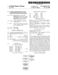
[0012]
FIG. 5 is an information ?ow diagram showing
embodiments of information being transferred between a
control block, output block, and transducer block.
DETAILED DESCRIPTION OF THE INVENTION
control system’s control strategy. However, when the undes
[0013]
ired condition is not part of the hardware or software, the
smart ?eld device by itself may be unable to communicate the
presence of the undesired condition. This could include con
ditions like insuf?cient air pressure to a pneumatic digital
valve.
invention will be described below. In an effort to provide a
BRIEF DESCRIPTION OF THE INVENTION
[0003] Certain embodiments commensurate in scope with
the originally claimed invention are summarized below.
These embodiments are not intended to limit the scope of the
claimed invention, but rather these embodiments are intended
only to provide a brief summary of possible forms of the
invention. Indeed, the invention may encompass a variety of
One or more speci?c embodiments of the present
concise description of these embodiments, all features of an
actual implementation may not be described in the speci?ca
tion. It should be appreciated that in the development of any
such actual implementation, as in any engineering or design
project, numerous implementation- speci?c decisions must be
made to achieve the developers’ speci?c goals, such as com
pliance with system-related and business-related constraints,
which may vary from one implementation to another. More
over, it should be appreciated that such a development effort
might be complex and time consuming, but would neverthe
less be a routine undertaking of design, fabrication, and
manufacture for those of ordinary skill having the bene?t of
this disclosure.
forms that may be similar to or different from the embodi
ments set forth below.
[0004] In a ?rst embodiment, a system includes an indus
[0014] When introducing elements of various embodi
ments of the present invention, the articles “a,” “an,” “the,”
trial controller con?gured to control a ?rst ?eld device. The
?rst ?eld device includes an actuator and a positioner coupled
the elements. The terms “comprising,” “including,” and “hav
to the actuator. The positioner is con?gured to position the
actuator. The ?rst ?eld device is con?gured to detect an
undesired condition and to communicate the undesired con
dition to the industrial controller by using a ReadBack facility
of the ?rst ?eld device.
[0005] In a second embodiment, a method includes deter
mining a state of a ?eld device. And if the state includes an
undesired condition, then deriving an indication of an undes
ired condition and adding the indication of the undesired
condition to a ReadBack facility. The method further includes
communicating the indication to a control block.
[0006] In a third embodiment, a non-transitory tangible
computer-readable medium storing a plurality of instructions
executable by a processor of an electronic device, the instruc
tions include instructions to determine a state of a ?eld device.
If the state includes an undesired condition, the instructions
also include instructions to derive an indication of the undes
ired condition. The instructions further include instructions to
add the indication of the undesired condition to a ReadBack
facility and instructions to communicate the indication to a
control block.
BRIEF DESCRIPTION OF THE DRAWINGS
[0007]
These and other features, aspects, and advantages of
the present invention will become better understood when the
following detailed description is read with reference to the
accompanying drawings in which like characters represent
like parts throughout the drawings, wherein:
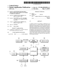
[0008] FIG. 1 is a schematic diagram of an embodiment of
an industrial control system, including an industrial control
ler and a valve;
and “said” are intended to mean that there are one or more of
ing” are intended to be inclusive and mean that there may be
additional elements other than the listed elements.
[0015] Certain industrial control systems include industrial
controllers suitable for interfacing with a variety of ?eld
devices, such as sensors, pumps and valves. For example, an
industrial controller may direct a pneumatic valve to set the
valve’s actuator at a certain position to affect the ?ow through
the valve. However, desired functioning of the pneumatic
valve may be affected by undesired conditions, such as insuf
?cient air pres sure used to control the valve or a foreign object
in the valve. In order for the industrial controller to take
appropriate ameliorative action, undesired conditions may be
detected and communicated to the industrial controller.
[0016] In ?eld devices compliant with a Foundation Field
bus protocol, the ?eld devices will have the capability to
transmit feedback to the industrial controller issues that relate
to the hardware and/or software of the device on a periodic
basis. For example, the Foundation Fieldbus protocol, Inter
national Electrotechnical Commission (IEC) 61804, is a two
way communication system, which interconnects various
?eldbus devices such as sensors, pumps, valves, industrial
controllers, and the like, via a local area network (LAN).
However, the Foundation Fieldbus protocol does not include
the same feedback ability for communicating undesired con
ditions, such as insu?icient air pressure, because the ?eld
device itself is not defective or faulted. The insu?icient air
pressure may be attributed to an air supply external to the ?eld
device. Other undesired conditions may include low actua
tion amperage, a sticky valve, or a foreign object in a valve. It
may be plausible to implement a solution that uses additional
function blocks to speci?cally monitor parameters like sup
ply air pressure. However, the use of the additional function
Aug. 21,2014
US 2014/0236318 A1
blocks requires additional processing power and bandwidth,
[0019]
which may result in slower execution. In some cases the host
tively connected to a plant data highway 26 suitable for
may poll for an undesired condition during a speci?ed time,
enabling communication between the depicted computer 12
and other computers 12 in the plant. Indeed, the industrial
control system 10 may include multiple computer systems 12
interconnected through the plant data highway 26. The com
puter system 12 may be further communicatively connected
often close to 30 or more seconds. A “macrocycle,” as dis
cussed herein, may refer to a cycle of scheduled function
block execution, scheduled communication time, and a por
tion of time reserved for asynchronous communications (e.g.,
alerts and/or downloads) by devices on a communications
segment (e.g., an H1 segment).
[0017] The disclosed embodiments provide a system and
method to provide ?eld device feedback, especially for those
parameters not included in the health de?nitions of the Foun
dation Fieldbus protocol. In one embodiment, by utiliZing the
ReadBack facility of Foundation Fieldbus function blocks,
the present techniques are able to detect and communicate an
undesired fault condition and recovery from the fault condi
tion to the industrial controller without the use of additional or
custom function blocks and without the need for additional
bandwidth within the macrocycle. Furthermore, because
Further, the computer system 12 is communica
to a unit data highway 28, suitable for communicatively cou
pling the computer system 12 to an industrial controller 30.
The industrial controller 30 may include a processor 32 and
memory 42 suitable for executing a control strategy useful in
automating a variety of plant equipment, such as a turbine
system 34 (e.g., gas turbine, steam turbine, water turbine,
wind turbine etc.), a power generation system, a heat recovery
steam generator (HRSG), a gas treatment system, a tempera
ture sensor 36, a valve 38, and a pump 40. This may be
implemented through the use of one more function blocks 41
executable by the industrial controller 30. In some embodi
ments, the industrial controller 30 may be a proportional
when a ?eld device is not functioning as desired due to an
integral-derivative (PID) controller. Accordingly, the PID
undesired condition, it may be very useful to take ameliora
tive action as quickly as possible. If the techniques described
herein are enabled during commissioning, the disclosed
embodiments may be able to almost immediately switch to an
controller may be implemented by a PID function block. The
function blocks 41 may include computer instructions or
computer logic executable by processor 32. The industrial
controller 30 may communicate with a variety of ?eld
OOS (Out of Service), Manual, or Local Override Mode,
devices, including but not limited to ?ow meters, pH sensors,
which signals to the industrial controller that the ?eld device
is not responding because a fault state is active. The industrial
temperature sensors, vibration sensors, clearance sensors
controller can then take further actions based on feedback,
which may include information concerning undesired ?eld
device conditions (e.g., low actuation air pressure, low actua
tion amperage, sticky valve, or foreign object in a valve).
[0018]
Turning to FIG. 1, an embodiment of an industrial
control system 10 is depicted. The industrial control system
10 may include a computer system 12 suitable for executing
a variety of ?eld device con?guration and monitoring appli
cations, and for providing an operator interface through
(e.g., measuring distances between a rotating component and
a stationary component), pressure sensors, pumps, actuators,
valves, and the like. In some embodiments, the industrial
controller 30 may be a MarkTM VIe controller system, avail
able from General Electric Co., of Schenectady, N.Y., includ
ing a triple modular redundant (TMR) controller 30 having
three cores (e.g., R, S, T) suitable for redundant controller
operations. For example, the R, S, and T cores may vote to
determine control actions.
which an engineer or technician may monitor the components
[0020]
In the depicted embodiment, the turbine system 34,
of the control system 10. Accordingly, the computer 12
the temperature sensor 36, the valve 38, and the pump 40 are
includes a processor 14 that may be used in processing com
puter instructions, and a memory 16 that may be used to store
communicatively connected to the industrial controller 30 by
using linking devices 44 and 46 suitable for interfacing
computer instructions and other data. The computer system
between an I/O network 48 and an H1 network 50. For
12 may include any type of computing device or a combina
example, the linking devices 44 and 46 may include the
tion of computing devices suitable for running software appli
FG-100 linking device, available from Softing AG, of Haar,
cations, such as a laptop, a workstation, a tablet computer, or
Germany. As depicted, the linking devices 44 and 46 may
include processors 52 and 54, respectively, useful in execut
ing computer instructions, and may also include memory 56
and 58, useful in storing computer instructions and other data.
a handheld portable device (e.g., personal digital assistant or
cell phone). Indeed, the computer system 12 may include any
of a variety of hardware and/ or operating system platforms. In
accordance with one embodiment, the computer 12 may host
In some embodiments, the I/O network 48 may be a 100
an industrial control software, such as a human-machine
Megabit (MB) high speed Ethernet (HSE) network, and the
interface (HMI) software 18, a manufacturing execution sys
tem (MES) 20, a distributed control system (DCS) 22, and/or
a supervisor control and data acquisition (SCADA) system
24. A commissioning/decommissioning system 25 may be
included in the HMI 18, MES 20, DCS 22, and/or SCADA 24,
and used to commission and/or decommission certain
devices, as described in more detail below. The HMI 18, MES
20, DCS 22, SCADA 24 and/or commissioning/decommis
sioning system 25, may be stored as executable code instruc
H1 network 50 may be a 31.25 kilobit/ second network.
Accordingly, data transmitted and received through the I/O
network 48 may in turn be transmitted and received by the H1
network 50. That is, the linking devices 44 and 46 may act as
bridges between the I/O network 48 and the H1 network 50.
For example, higher speed data on the I/O network 48 may be
buffered, and then transmitted at suitable speed on the H1
network 50. Accordingly, a variety of ?eld devices may be
linked to the industrial controller 30 and to the computer 12.
tions on non-transitory tangible computer readable media,
For example, the ?eld devices 34, 36, 38, and 40 may include
such as the memory 16 of the computer 12. For example, the
computer 12 may host the ToolboxSTTM and/ or ControlSTTM
industrial devices, such as Fieldbus Foundation devices that
include support for the Foundation H1 bi-directional commu
software, available from General Electric Company, of
nications protocol. The ?eld devices 34, 36, 38, and 40 may
also include support for other communication protocols, such
Schenectady, N.Y.
US 2014/0236318 A1
Aug. 21,2014
(PNO) protocol.
combination thereof. As described above, undesired condi
tions may hinder the operation of the ?eld device 38. Accord
ingly, FIG. 2 describes an exemplary pneumatic device as
[0021]
Each of the linking devices 44 and 46 may include
well as undesired conditions, such as insu?icient air pressure.
one or more segment ports 60 and 62 useful in segmenting the
[0024] FIG. 2 is a schematic diagram illustrating an
embodiment of the industrial controller 30 controllably
coupled to the pneumatic valve 38 of FIG. 1. The pneumatic
valve 38 may include a valve body, a ?uid path through the
as those found in the HART® Communications Foundation
(HCF) protocol, and the Pro?bus Nutzer Organization e.V.
H1 network 50. For example, the linking device 44 may use
the segment port 60 to communicatively couple with the
devices 34 and 36, while the linking device 46 may use the
segment port 62 to communicatively couple with the devices
38 and 40. Distributing the input/output between the ?eld
valve body, an inlet, and outlet, and a valve member that move
devices 34, 36, 38, and 40, by using, for example, the segment
maintaining fault tolerance, redundancy, and improving com
the pneumatic valve 38 may includes a positioner 116 and an
actuator 118. The positioner 116 may be con?gured to receive
a desired valve position from the controller 30 and provide a
munications time.
[0022] Each ?eld device 34, 36, 38, and 40 may include a
signal, such as air, to the actuator 118. An exemplary posi
tioner 116 may be General Electric’s Masoneilan SVI digital
ports 60 and 62, may enable a physical separation useful in
in the ?uid path to open and close the ?ow path. In addition,
respective device description (DD) ?le, such as the depicted
valve positioner with built-in magnetic position sensing and
DD ?les 64, 66, 68, and 70. The DD ?les 64, 66, 68, and 70
may be written in a device description language (DDL), such
pressure sensors, available from General Electric Co., of
Schenectady, N.Y. The actuator 118 may then change the
signal into mechanical energy to move the valve member to
the desired position. The valve member may move in either a
linear or rotary manner. In a linear valve, the throughput of the
as the DDL de?ned in the International Electrotechnical
Commission (IEC) 61804 standard. In some embodiments,
the ?les 64, 66, 68, and 70 are tokenized binary ?les. That is,
the DD ?les 64, 66, 68, and 70 may include data formatted in
a tokenized binary format useful in reducing the size of the
DD ?les 64, 66, 68, and 70. The DD ?les 64, 66, 68, and 70
may each include one or more function blocks 72, 74, 76, and
78. The function blocks 72, 74, 76, and 78 may include
computer instructions or computer logic executable by pro
cessors 80, 82, 84, and 86. Indeed, the function blocks 72, 74,
76, and 78 may be instantiated into memory 88, 90, 92, 94,
and then executed by the processors 80, 82, 84, and 86,
respectively. Each of the DD ?les 64, 66, 68, and 70 may also
include device information 96, 98, 100, and 102, such as
manufacturer identi?cation (ID), device type, device revi
sion, DD revision, and/or update revision, which may be used
during commissioning or decommissioning by the commis
valve may be changed by moving the valve member linearly
in the valve. In a rotary valve, the throughput of the valve may
be changed by rotating the valve member in the valve.
[0025] The actuator 118 may be different types including
wheel and axle, pneumatic, hydraulic, solenoid, screw and
manual. For example, in a pneumatic valve 38, the positioner
116 may increase or decrease the air supplied to the actuator
118 based on the desired valve position. Accordingly, the air
supplied to the actuator 118 may move the valve member to
the desire valve position. More speci?cally, in a functioning
pneumatic valve 38, the industrial controller 30 may send
control actions through conduit 120, according to a control
strategy for the control system, to the positioner 116, which
includes a desired valve position. The positioner 116 is then
sioning/decommissioning system 25. In this way, the ?eld
devices 34, 36, 38, and 40 may contribute control logic and
able to determine the current position of the actuator 118, for
other computer instructions towards the execution of pro
cesses in the industrial process control system 10.
[0023] In one example, a placeholder may be created by the
to supply to the actuator 118 to move the valve member to the
example, by using conduit 122, and determine the air pres sure
desired position. The positioner 16 may the supply the deter
holder may be an object stored in memory 16 that represents
the ?eld device 38. Accordingly, a user may pre-commission
a system by creating one or more of the placeholder, each of
the placeholders representing the device 38, and then use the
mined amount of air from the air supply 126. In the depicted
embodiment, the air supply 126 is located external to the
pneumatic valve 38. The air may then be applied to the actua
tor 118 through ?uid conduit 124 and the position of the valve
member may be changed as desired.
[0026] An undesired condition may arise when the posi
placeholder(s) during commissioning of the physical ?eld
tioner 116 is unable to receive suf?cient air pressure from the
device 38. The placeholder may include physical device (PD)
tag, manufacturer ID, device type, device revision, DD revi
sion, and/or update revision representative of the ?eld device
culty moving the actuator 118 to the desired position. In some
38. The PD tag may include a device name useful in identi
undesired condition (e. g., low air supply pressure) because
fying the device 38. Likewise, the manufacturer ID may
include information identifying the manufacturer of the
device 34. The device type may be suitable for identifying the
type of device (e.g., valve, sensor, actuator), while the device
the undesired condition is external to the valve 38 and thus not
included in hardware and/or software health de?nitions of the
valve 38. To account for this, the user may extend the control
strategy and execute additional function blocks to collect the
commissioning/decommissioning system 25. The place
air supply 126, resulting in the positioner 116 having di?i
cases, the industrial controller 30 may not be aware of the
revision may be a version number indentifying the device
information; however, this may slow down the control pro
version. Likewise, the DD revision may identify the DD
cess and reduce the quality of control. If the undesired con
version, such as a DD ?le version included in the device 38. It
dition is unaccounted for, the controller 30 may continue
following the control strategy and operate as if the valve is in
should be appreciated that in another embodiment, the device
38 may be commissioned without using the placeholder. In
one embodiment, ?eld device 38 may be a ?ow control
device, such as a valve, ?ow and/or pressure regulator, ?ow
restrictor or any combination thereof. For example the ?eld
device 38 may be a valve such as a pneumatic actuated valve,
a hydraulic actuated valve, an electricity driven valve or any
the correct position. This can cause undesired behavior in the
system 10. For example, if the controller 30 derives that the
valve 38 is more open than it actually is, this could result in a
back up in pipe 123. In addition, when the controller 32 is a
PID controller, if the controller 32 is unaware that the valve 38
is unable to move to follow the setpoint, the controller 32 may
Aug. 21,2014
US 2014/0236318 A1
continue to integrate causing the error to build up the control
output value, which may make the recovery process dif?cult.
Thus, undesired conditions may be detected and communi
cated back to the industrial controller 30 as quickly as pos
sible to, for example, more properly actuate the valve 38 or
use a backup valve.
Local Override Mode, which immediately stops the ?eld
device from trying to follow the industrial controller’s
instructions.
[0031]
Next, the process 128 may add (block 136) indica
electric, electro-pneumatic, hydraulic, and electro-hydraulic
tion data of the undesired condition to the ReadBack Facility.
As will be described in more detail in reference to FIG. 5, the
ReadBack Facility may be part of an Output function block
that allows for the Output function block to feedback a signal
to a control block, for example, through a sub-status/category.
valves), ?ow meters, pH sensors, temperature sensors, vibra
tion sensors, clearance sensors (e.g., measuring distances
between a rotating component and a stationary component),
This may be implemented using the BKCAL_OUT and
BKCAL_IN parameters. Speci?cally, Block 136 may be
implemented by writing to the BKCAL_OUT parameter on
pressure sensors, pumps, and actuators. Similarto insuf?cient
the Output function block. The process 128 then uses the
air pressure in the pneumatic valve 38, undesired conditions
ReadBack facility to communicate (block 138) the indication
may not be included in the hardware and/ or software de?ni
tions of the ?eld device. For example, an electric valve that
relies on electricity to activate the valve may suffer from an
undesired condition such as insuf?cient power or incorrect
frequency of the input from an external power source. Simi
larly, a wind pump that relies on wind power to supply energy
to the pump may suffer from an undesired condition such as
insuf?cient wind ?ow. Accordingly, FIG. 3 describes one
data to the industrial controller 30, which may be imple
mented by reading the BKCAL_IN parameter on the control
block. Similarly, if the undesired condition disappears, the
[0027] The techniques described below may be used in
other ?eld devices 38 including different types of valves (e.g.,
technique to communicate the undesired conditions to the
controller 30.
[0028]
FIG. 3 is a ?owchart ofan embodiment ofa process
128 suitable for detecting, communicating, and ameliorating
an undesired condition using an embodiment of the ?eld
device feedback utiliZing, for example, a ReadBack facility.
As described above, the ?eld device may be commissioned by
the commissioning/decommissioning system 25 using a
placeholder representative of the ?eld device with the Read
Back facility.
[0029] The process 128 may be implemented by using
computer instructions stored in a non-transitory computer
readable medium, such as the memory of a computer, server,
laptop, tablet, cell phone, mobile device, or similar process
ing or computing device. The process 128 may begin by
determining (block 130) the condition of the ?eld device 38.
The condition of the ?eld device 38 may be determined by
various sensors in the ?eld device 38. For example, in the
pneumatic valve 38 described in FIG. 2, a condition of “insuf
?cient air pressure” may be determined when a sensor in the
air supply 116 detects insu?icient pneumatic pressure being
supplied. Similarly, another condition of “foreign object
present” may be determined when a sensor located within the
pipe 123 detects a foreign object within the pipe. Other sen
sors in the pneumatic device 38 may be used to determine
other conditions such as “valve not moving properly” when
the vale is jamming, sticking, or generally not responding
properly. A condition of “functioning properly” may be deter
mined when none of the sensors in the ?eld device 38 detect
an issue.
[0030]
The process 128 then determines whether (decision
block 132) the condition is an undesired condition. As will be
described in more detail with reference to FIG. 5, one
embodiment utilizes a function block, such as a transducer
function block, to determine whether the condition has to be
reported. If the condition is not an undesired condition, the
process 128 may then use the ReadBack facility to commu
nicate a status of good so that the control algorithm may
resume normal control operations.
[0032]
In one embodiment, the blocks 130, 134, 136, and
138 may execute within a Time N 140. In some embodiments,
Time N 140 is 1-2 macrocycles, where a “macrocycle” refers
to a cycle of scheduled function block execution, scheduled
communication time, and a portion of time reserved for asyn
chronous communications. In other words, a macrocycle may
be one control loop execution. The Foundation Fieldbus pro
tocol may allow macrocycles to be con?gured at between
10-250, 100-500, 250-1000, 750-3000 or more milliseconds.
Thus, by using the ReadBack techniques disclosed herein, the
Time N 140 may be as fast as 10-250 milliseconds or 250
3000 milliseconds. The techniques herein enable a quicker
noti?cation of an undesired condition because it enables the
undesired condition to be reported in 1-2 loop executions as
compared to additional custom function blocks, which may
poll for the undesired condition after a speci?ed time, such as
30 seconds. A more detailed explanation of the functioning of
the ReadBack facility within a macrocycle is described in
FIG. 4.
[0033] FIG. 4 is diagram of an embodiment of a macrocycle
146 including an Output function block (Analog or Digital)
152 having ReadBack facility for indicating the presence of
an undesired condition. During the execution of the macro
cycle 146, one or more function blocks may execute at desired
time slots. As an example, these function blocks may include
Alarm Detection Function Blocks, Analog Input Function
Blocks, Calculation/Logic Function Blocks, Filter Function
Blocks, and Arithmetic Function Blocks. In the depicted
embodiment, the macrocycle 146 begins by executing func
tion block 1 (FB1) at time slot 148 followed by function block
2 (FB2) at time slot 150, and so on. When the macrocycle
reaches the Output function block (e.g., Analog Output (AO)
or the Digital Output (DO)) time slot 152 and an undesired
condition is detected, the Output function block may use the
ReadBack facility to indicate (block 154) the undesired con
dition. The macrocycle 146 may continue executing function
blocks until reaching function block N (FBN) at time slot 156.
Then, the macrocycle 146 may repeat execution of function
blocks, for example, by starting over with FB1 at time slot
process 128 returns to block 130 and continues to monitor the
148. By using the ReadBack facility, the techniques described
condition (e.g., “insuf?cient air pressure” or “functioning
properly”) of the ?eld device. If the condition of the ?eld
device is an undesired condition, the process 128 puts (block
herein provide for deterministic execution of processes asso
ciated with the controller 30. In other words, control may be
provided at substantially the same execution time, even when
undesired conditions are detected, and control actions may be
134) the ?eld device (e. g., valve 38) into a fault state such as
Aug. 21,2014
US 2014/0236318 A1
modi?ed correlative with the detected conditions. Accord
ingly, the undesired conditions may be overcome by control
actions or noti?cations may be provided, thus improving the
safety of the system 10.
tion block remains unchanged, until a new value is set by an
operator. In this embodiment, the valve positioner 116 moni
tors the undesired condition (i.e. insuf?cient supply air pres
sure). The valve positioner 116 and/or other sensors and
[0034] Referring back to FIG. 3, once the industrial con
troller 30 receives the indication data, the process 128 may
determine (block 142) at least one action to take in order to
ameliorate or eliminate the undesired condition. For example,
actuators can be used to monitor other/multiple undesired
a backup valve may be used as an alternative to the malfunc
tored at the same time. The transducer block 162 may thenuse
tioning valve, ?uids may be transferred via an alternate pipe,
its ReadBack facility to return (data ?ow 176) a sub-status of
Initiate Fault State. Once the output block 160 receives the
Initiate Fault State sub-status, it may switch (process block
178) the output function block 160 from Cascade mode into
Out of Service, Manual, or Local Override mode. In the
Foundation Fieldbus protocol, these modes are part of output
alarms may be set, other systems may be noti?ed, and so on.
Finally, the process 128 may execute (144) the action to
ameliorate or eliminate the undesired condition. As will be
described in further detail in FIG. 5, block 142 and 144 may
be executed in the control block.
[0035]
FIG. 5 is an information diagram showing embodi
ments of an information ?ow between a control function
block 158, output functionblock 160, and transducer function
block 162 in an exemplary embodiment. The information
diagram may be executed in one macrocycle or one control
loop. In some embodiments, the control block 158 is executed
using the industrial controller 30 of FIG. 1. The industrial
controller 30 is communicatively coupled to a ?rst ?eld
device, such as the valve 30 having the output block 160 and
the transducer block 162. In the depicted embodiment, the
output block 160 and the control block 158 may communicate
through one or more ?eldbus publisher/ subscriber (periodic)
communication connections, as described above. The output
block 160 and the transducerblock 162 may be programmati
cally used in certain control algorithms so that data computed
by using one or more function blocks may be used as inputs to
other function blocks. It should be appreciated that, alterna
tively, all of the function blocks may be included in the same
?eld device, e.g., valve 38, and/ or in the controller 30.
conditions, such as insuf?cient hydraulic pressure, insu?i
cient wind power, or improper electric power (e.g. incorrect
frequency). Also, potential undesired conditions can be moni
function blocks including the Analog Output (AO), the Digi
tal Output (DO), or a combination thereof. The new mode
may stop the output block 160 from using the ?rst SetPoint
and may instead set the second SetPoint to a speci?ed value.
Thus, the output block 160 may stop calculating the second
SetPoint.
[0038] The output block 160 may the use the ReadBack
facility to return (data ?ow 180) a sub-status of Failed State
Active to notify the control function block 158 of the undes
ired condition in the ?eld device. Additionally or altema
tively, output function block 160 may return a sub-status of
NotInvited or NotSelected. The ReadBack facility may be
implemented by the BKCAL_OUT parameter on the output
function block 160. The BKCAL_OUT parameter is used to
communicate a value and a status, including sub-status, that
may be required by the BKCAL_IN of another function
block. The BKCAL_OUT parameter may be communica
tively coupled to the BKCAL_IN parameter on the control
function block 158. The two function blocks may communi
To better illustrate the information ?ow, the function
cate through a publish/subscribe protocol, which allows for
blocks 158, 160, and 162 can be described in relation to the
the communications to be fast and deterministic in schedule.
pneumatic valve 38 in FIG. 2, and may include Foundation
The BKCAL_OUT parameter may be used to help provide
[0036]
Fieldbus capabilities. The industrial controller 30, through
smooth mode transfer when the mode on the output function
the control function block 158, may implement a control
strategy 164 to guide the functioning of the rest of the control
system. Alternatively, the control function block 158 may be
included in the ?eld device 38. In some embodiments, the
control block 158 may be a proportional-integral-derivative
block 160 is changed by providing a value and status, includ
ing sub-status, to the control function block 158. The dis
(PID) control block 158. Following the control strategy 164,
the control block 158 may begin by calculating (process block
166) a desired valve position and passing (data ?ow 168) the
the output block 160 may return a status that indicates the
limited SetPoint so that recovery may be bumpless.
information to the output function block 160, for example, as
a ?rst SetPoint. Because the output functionblock 160 may be
put function block 160 is assigned to a ?eld device, such as a
valve, the BKCAL_OUT parameter may be used to commu
nicate information such as actuator position. In other words,
in Cascade Mode (e. g., a mode that uses a master-slave con
?guration), it may use the ?rst SetPoint to decide the value
(process block 170) for a second SetPoint and pass (data ?ow
172) the second SetPoint to the transducer function block
162. This second SetPoint may be used to translate a standard
?eldbus value to a value (analog or digital) that can be used by
the transducer function block 162. In normal operation, as
described above, the valve may move the actuator and the
valve member to the desired position.
[0037] However, in the case of an undesired condition, the
transducer function block 162 through the valve positioner
may detect the condition and switch (process block 174) the
transducer block 162 to Out-of-Service or Manual mode. In
closed embodiments may instead use the sub-status in the
BKCAL_OUT parameter to inform the control function
block 158 that an undesired condition is present. In addition,
[0039]
Without the disclosed embodiments, when the Out
without the disclosed embodiments, the BKCAL_OUT
parameter may be used to communicate conditions affecting
mode and status that are related to the hardware and/or soft
ware health of the ?eld device using the ReadBack facility.
The disclosed embodiments, on the other hand, use the Out
put function block 160 that communicates undesired condi
tions not included in the hardware and/or software health of
the ?eld device, such as the insuf?cient air pressure being
supplied by the air supply 126 or other conditions related to
systems external to the ?eld device. Thus, the disclosed
embodiments have adapted the BKCAL_OUT parameter to
communicate conditions that previously were either not
Out-of-Service mode, the function block is inactive and the
being communicated to the control strategy or were commu
output of the function block maintains the last value or a
nicated using additional and/or custom function blocks to
communicate to the control strategy.
failure action value. In Manual mode, the output of the func
Aug. 21,2014
US 2014/0236318 A1
[0040] Once the sub-status is read by the control function
block 158, the control function block 158 may automatically
use the control strategy 164 to determine an ameliorative
action (process block 182). For example, the control function
the ?rst ?eld device comprising:
an actuator;
a positioner coupled to the actuator and con?gured to
position the actuator, wherein the ?rst ?eld device is
con?gured to detect an undesired condition and to
communicate the undesired condition to the industrial
block 158 may use a second ?eld device, like an alternative
valve, as a backup. This provides for redundancy in the opera
tion for the ?rst ?eld device. Other ameliorative actions
include shutting down a pump, disallowing the process to
start, issuing alerts, communicating with an operator or with
other systems. In addition, when the control function block
158 is a PID control function block 158, the PID control
function block 158 may stop integrating the error and chang
ing the SetPoint. This may assist in a faster recovery because
once recovered, the Output Block 160 will resume using the
most recent SetPoint. Accordingly, it should be appreciated
that the integrating should cease as quickly as possible, which
controller by using a ReadBack facility of the ?rst
?eld device.
2. The system of claim 1, wherein the ?rst ?eld device
comprises a Foundation Fieldbus ?rst ?eld device con?gured
to communicate with the industrial controller.
3. The system of claim 2, wherein the Fieldbus Foundation
?rst ?eld device comprises a Foundation Fieldbus digital
output (DO) function block, a Foundation Fieldbus analog
output (AO), or a combination thereof, having the ReadBack
facility.
may be accomplished through the techniques described
4. The system of claim 3, wherein the ReadBack facility
herein. Speci?cally the integrating may cease within one
comprises a Fault State Active sub-status code/category con
?gured to indicate the undesired condition.
5. The system of claim 4, wherein the Fault State Active
macrocycle.
[0041] Similar to reporting an undesired condition, recov
ery may be accomplished within one macrocycle. In the
recovery process, the Output function block 160 may notify
the control function block 158 using the same ReadBack
facility. Accordingly, the control function block 158 may
resume normal operation within one macrocycle or one con
trol loop execution.
sub-status code/category is con?gured to be transmitted by
publish/subscribe protocol from the BKCAL_OUT param
eter of the Foundation Fieldbus digital output (DO) function
block, the Foundation Fieldbus analog output (AO), or a
combination thereof.
6. The system of claim 3, wherein the ?rst ?eld device is
con?gured to set the Foundation Fieldbus digital output (DO)
[0042] In other embodiments, such as in when the function
blocks are in a cascade loop, the control function block 158
function block, the Foundation Fieldbus analog output (AO),
may act similarly to the Output ?lnction block 160 and use its
ReadBack facility to notify another control function block
158 of the undesired condition. In other words, the presence
Override mode.
7. The system of claim 1, wherein the ?rst ?eld device
comprises a valve having an inlet and an outlet, and wherein
the actuator is con?gured to enable a ?ow between the inlet
and the outlet.
of the undesired condition may be passed between coupled
control function blocks 158 through the ReadBack facility.
Accordingly, similar to the techniques described above, the
time to communicate the presence of an undesired condition
between the control function blocks 158 may be one macro
cycle 146.
[0043] Technical effects of the described embodiments
include e?iciently enabling the ?eld device 38 to communi
cate the presence of an undesired condition, such as insu?i
cient pneumatic pressure, to a controller 30. In particular, the
?eld device 38 may be able to utilize the feedback function,
speci?cally the ReadBack facility, on the Output function
block 160. In other words, the ?eld device 38 may be able to
communicate the presence of the undesired condition using
the existing function blocks without additional bandwidth.
[0044] This written description uses examples to disclose
the invention, including the best mode, and also to enable any
person skilled in the art to practice the invention, including
making and using any devices or systems and performing any
incorporated methods. The patentable scope of the invention
is de?ned by the claims, and may include other examples that
occur to those skilled in the art. Such other examples are
intended to be within the scope of the claims if they have
structural elements that do not differ from the literal language
of the claims, or if they include equivalent structural elements
with insubstantial differences from the literal language of the
claims.
1. A system comprising:
an industrial controller con?gured to control a ?rst ?eld
device;
or a combination thereof to a Manual, Out of Service, or Local
8. The system of claim 1, wherein the positioner comprises
a linear positioner con?gured to transform linear motion into
an actuator position, a rotary positioner con?gured to trans
form rotary motion into the actuator position, or a combina
tion thereof.
9. The system of claim 1, wherein the industrial controller
is con?gured to control a second ?eld device based on the
undesired condition, and the second ?eld device is con?gured
to provide redundant operations for the ?rst ?eld device.
10. The system of claim 1, comprising a commissioning
system having a placeholder representative of the ?rst ?eld
device, wherein the commissioning system is con?gured to
use the placeholder to commission the ?rst ?eld device.
11. The system of claim 1, wherein the system is an indus
trial control system comprising a gas turbine system, a gas
i?cation system, a steam turbine system, a wind turbine sys
tem, a water turbine system, a power generation system, or
any combination thereof.
12. A method, comprising:
determining a state of a ?eld device;
deriving a ?rst indication of an undesired condition if the
state includes an undesired condition, then;
adding the ?rst indication of the undesired condition to a
ReadBack facility; and
communicating the ?rst indication to a control block.
13. The method of claim 12, wherein communicating the
indication comprises using a Foundation Fieldbus communi
cations protocol.
14. The method of claim 13, comprising placing the ?eld
device in Manual, Out of Servicer, or Local Override mode.
US 2014/0236318 A1
15. The method of claim 12, wherein the ReadBack facility
comprises a Fault State Active sub-status code/category con
?gured to include an indication of the undesired condition.
16. The method of claim 12, comprising:
deriving a second indication of a recovered condition if the
state includes a recovered condition, then;
adding the second indication of the recovered condition to
the ReadBack facility; and
communicating the second indication to a control block.
17. The method of claim 12, Wherein the ?eld device is
included in an industrial control system comprising a gas
turbine system, a gasi?cation system, a steam turbine system,
a Wind turbine system, a water turbine system, a power gen
eration system, or any combination thereof.
18. A non-transitory tangible computer-readable medium
storing a plurality of instructions executable by a processor of
an electronic device, the instructions comprising:
instructions to determine a state of a ?eld device;
instructions to derive an indication of an undesired condi
tion if the state includes an undesired condition, then;
instructions to add the indication of the undesired condi
tion to a ReadBack facility; and
instructions to communicate the indication to a control
block.
19. The medium of claim 18, Wherein communicating the
indication comprises using a Foundation Fieldbus communi
cations protocol.
20. The medium of claim 18, Wherein the ReadBack facil
ity comprises a Fault State Active sub-status code/category
con?gured to include an indication of the undesired condi
tion.
Aug. 21,2014