1
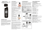
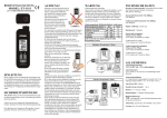
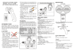
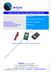
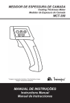
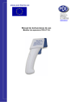
OPERATING INSTRUCTIONS
MODEL: ET-111
2 IN 1 COATING THICKNESS GAUGE
INTRODUCTION
This instrument is a 4 digit, portable, easy to use and
compact-sized digital “ferrous” or “non-ferrous” coating
designed for simply one hand operation. Meter comes with
backlight LCD display and Auto Power Off (60 seconds
approx.) to extend battery life.
SAFETY INFORMATION
It is recommended that you read the safety and operation
instructions before using the coating thickness gauge.
DANGER
When the UV LED function is turned on, it will radiate
intense UV light during operation. Since UV light can
be harmful to eyes, do NOT look directly into the UV
light, even through an optical instrument. In case of the
light reflection, UV protective glasses are required to
use in order to avoid damage by the light.
CAUTION
● Do not use the unit near any device which generates
strong electromagnetic radiation or near a static electrical
charge, as these may cause errors.
● Do not use the unit where it
be exposed to corrosive or explosive gases. The unit may be
damaged, or explosion may
occur.
● Do not keep or use this unit in
an environment where it will be
directly illuminated by sunshine, or where it condensation. If you do, it may be deformed, its insulation may
damaged, or it may no longer function according to
specification.
● Do not place the meter on or around hot objects
(70°C/158°F). It may cause damage to the case.
● If the meter is exposed to significant changes in ambient
temperature, allow 30 minutes for temperature stabilization, before taking measurement.
● Condensation may form on the sensor when going from
cold to hot environment. Wait
for 10 minutes for condensation
to dissipate before taking
measurements.
● This unit is not constructed to
waterproof and dustproof. Do
not use it in a wet or very dusty
environment.
● In order to take accurate measurement, make sure the sensing
tip contacts the coated surface
tightly without tilting.
● Please make sure there is no air
bubbles between substrate and
coating.
● Substrate Zeroing Calibration:
:Must be implemented
for each use.
● Two point calibration:
:Must implement for frequent
testing points to increase measuring accuracy.
● The enclosed zeroing plates are only suitable for the use
of calibration of coating thickness meter itself. Apart
from that, the meter should be performed two point calibration methods to get accurate readings before use.
The zeroing on specific material substrate still needs to
be done before taking formal measurements, such as
Iron, Steel, Bronze, Copper, Nickel, Zinc, and SUS304
and so on, which is to avoid the measuring errors that
cause by the difference of individual substrates. The end
users can get much more accurate measuring readings
on the specific metal under test by doing two calibration
methods.
WARNING
ELECTROMAGNETIC FIELD INTERFERENCE
This instrument uses magnetic field method to measure
the coating thickness on ferrous metal base. If this meter
was placed in the environment with 20mG (mini Gauss) or
above, the accuracy would be affected. Suggest that the
meter should to put far away from the interfered source at
least 30cm.
SPECIFICATION
ELECTRICAL
Detectable Substrate Material:
:Ferrous metal (iron, steel)
and Non-Ferrous metal (copper, aluminum, zinc, bronze,
brass, etc.)
Ferrous Thickness Range:
:0 to 80.0mils, 0 to 2000µm.
Non-Ferrous Thickness Range:
:
0 to 40.0mils,0 to 1000µm.
Electromagnetic field strength:( unit = mini Gauss)
Electromagnetic Source
0cm
30cm
Cellular Phone Charger
50 ~ 500
<1
Notebook Power Supply
100 ~ 1000
<5
LCD Display
10 ~ 100
<1
Fan
100 ~ 1000
<5
Reading Lamp
400 ~ 4000
< 10
Any product with coil inside should be considered.
Recommended operating conditions ( >30cm)
Display Resolution:
:0.1mils/1µm.
Ferrous Accuracy:
:
±4dgts on 0 to 7.8mils.
±(3%+4dgts) on 7.9mils to 39.0mils.
±(5%+4dgts) on 39.1mils to 80.0mils.
±10dgts on 0 to 199µm.
±(3%+10dgts) on 200µm to 1000µm.
±(5%+10dgts) on 1001µm to 1999µm.
Non-Ferrous Accuracy:
:
±4dgts on 0 to 7.8mils.
±(3%+4dgts) on 7.9mils to 40mils.
±10dgts on 0 to 199µm.
±(3%+10dgts) on 200µm to 1000µm.
Response Time:
:1 second.
GENERAL
Operating Environment:
:-13°F to 122°F (-25°C to 50°C)
at < 75% R.H.
Storage Temperature:
:-13°F to 140°F (-25°C to 60°C),
0 to 80% R.H. with battery removed from meter.
Temperature Coefficient:
: 0.1x (specified accuracy) / °C
(< 18°C or > 28°C)
Auto Power Off:
:1 minute.
Standby Consuming Current:
:< 6µA.
Abnormal operating conditions (<30cm )
Battery:
:1.5V (AAA size) x 2pcs.
Battery Life:
:17 hours (continuity) typical with alkaline
battery.
” is displayed when
Low Battery Indication:The “
the battery voltage drops below the operating level.
Dimensions:
:120mm (H) x 40.4mm(W) x 29.2mm(D).
Weight:
:Approx. 100g (including battery).
Measuring:
1. Press the sensing tip of the gauge to contact coated
surface tightly, Wait for the reading to appear and
measurement is completed. (One “Beep” sound announced)
2. If the coating thickness is out of range, the meter shows
"----".
DEFINITION
Zeroing Plate
Ferrous is steel plate
Non-ferrous is Aluminum
plate
“
”
Press “ ” button each time, the display changes in the
following sequence:Lighting → UV light →OFF, it
can be operated in ON or Off mode.
”
1.Press “ ” button to turn on or off backlight function. It
can benefit users for reviewing display in dark environment.
2.Press “ ” button over 2 seconds to switch between mils
and µm. (1 mils = 25.4 µm)
“F/N”
Press “F/N” button each time, the display changes in the
following sequence: Auto → Ferrous→ Non-Ferrous
(Auto Mode and Ferrous Fixed Mode and Non-Ferrous
Fixed Mode.)
Peel off the
both side of
protection film
before use
“ ”
Quickly press “ ” button for substrate zeroing calibration.
Press “ ”button over 2 seconds to clear Calibrating Point..
“CAL”
1. When power is on, press “CAL” button over 2 seconds
to start calibration.
2. In calibration mode, when you finish calibrating, press
“CAL” button to complete calibrating procedure. .
“▲”
1. In calibration mode, press “▲”button to increase
Display's values.
“▼”
1.In calibration mode, press “▼”button to decrease Display's values.
INSTRUCTION
Peel off the protection films from foil before first use.
Calibrating Point Clearance:
:
In measuring mode, press “ ” button over 2 seconds, LCD
will display “oooo.” and start cleaning and zeroing substrate, one point and two point calibration. When calibration is not operated properly, the clearance function helps
users to start calibrating again.
FUNCTION BUTTON
“
Standard Coating Plate
return to measuring mode. “CAL” off.
Power on and off:
:
1.Keep the sensing tip of the meter away from any substrate or any magnetic field.
2.Gage automatically powers up and Measuring when
probe is pressed.
3. Auto Power Off (APO):
Leave the gauge without operation for 1 minute, power
turns off automatically.
CALIBRATION
※During calibration, Auto Power Off function will be
inactivated. If the LCD display "----", it can not zero the
substrate, one point calibration or two-point calibration.
When it is calibrated by user, its max calibrated value
is 43.3 mils /1100µm.
MAINTENANCE
Installing and Replacing Battery
Substrate Zeroing Calibration:
:
1. Press the sensing tip of the probe to contact Uncoated
surface tightly, Wait for the reading to appear and measurement is completed (one “Beep” sound announced),
then you can move the Gauge away. Press “ ” button (no
longer than 2 seconds) to calibrate substrate material or
foil. LCD displays 0 µm.
One Point Calibration:
:
1.Press the sensing tip of the probe to contact coated surface tightly, Wait for the reading to appear and measurement is completed (one “Beep” sound announced),
then you can move the Gauge away.
2.Press “CAL” button over 2 sec into calibration mode.
LCD will blink “CAL” icon. .
3.In calibration mode, use ▲ or ▼ button to adjust
readings until it matches the standard’s thickness.
4.Press “CAL” button to exit one point calibration and
return to measuring mode “CAL” off.
Two Point Calibration:
:
※During two point calibration, the foil and standard
coating plate 4.0 mils / 102µm can be replaced by
uncoated substrate and a standard coating plate with
known-thickness.
1.Press the sensing tip of the probe to contact Uncoated
surface tightly, Wait for the reading to appear and measurement is completed (one “Beep” sound announced)
Press “ ” button (no longer than 2 seconds) to calibrate
substrate material or foil. LCD displays 0 µm.
2.Press the sensing tip of the probe to contact coated surface tightly, Wait for the reading to appear and measurement is completed (one “Beep” sound announced), then
you can move the Gauge away. Press “CAL” button over
2 sec to enter calibration mode. LCD will display “CAL”
blinking.
3.In calibration mode, use ▲ or ▼ button to adjust
readings until it matches the standard’s thickness.
4.Press “CAL” button to exit two point calibration and
1.Power is supplied by 2pcs 1.5V (AAA SIZE).
” appears in the display when battery replace2.The “
ment is needed.
3.Remove the battery cover by gently sliding it onwards
the bottom of the meter.
4.Remove the batteries from battery compartment.
5.Replace with 2 new AAA batteries with polarity as indicated on the bottom of Battery Compartment.
6.Replace the Battery Cover.
CAUTION : When not in use for long periods remove
battery. Do not store in locations with
high temperatures, or high humidity.
Cleaning
Periodically wipe the case with a damp cloth and detergent, do not use abrasives or solvents.
Ver.1.1 02/09/2013