1
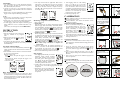
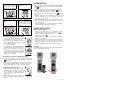
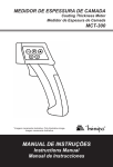
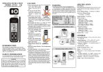
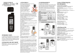
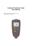
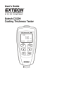
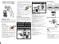
OPERATING INSTRUCTIONS
MODEL: PCE-CT 25
2 IN 1 COATING THICKNESS GAUGE
● If the meter continues to use over one minute, the accuracy of the measurement of the higher thickness will
become degraded. But the meter is still within its specified accuracy.
● Condensation may form on the sensor when going from
a cold to hot environment. Wait for 10 minutes for condensation to dissipate before taking measurements.
● This unit is not constructed
to be waterproof or dust
proof. Do not use it in a
wet or very dusty environment.
● In order to take accurate
measurement, make sure
the sensing tip contacts the coated surface tightly without tilting.
● Please make sure there is no air bubbles between substrate and coating.
● Substrate zeroing calibration must be implemented
for each use.
● Two point calibration MUST implement for frequent
testing points to increase measuring accuracy.
WARNING
INTRODUCTION
This instrument is a portable easy to use 3½ digit, compact-sized digital “ferrous” or “non-ferrous” coating
thickness gauge designed for simply one hand operation.
Meter comes with backlight LCD display, Data Logging
function and Auto Power Off (30 seconds approx.) to
extend battery life.
CAUTION
● Do not use the unit near
any device which generates
strong
electromagnetic
radiation or near a static
electrical charge, like
power generator, magnet…,
as these may cause errors.
● Do not use the unit where it may be exposed to corrosive or explosive gases. The unit may be damaged, or
explosion may occur.
● Do not keep or use this unit in an environment where it
will be directly illuminated by sunshine, or where it
condensation. If you do, it may be deformed, its insulation may be damaged, or it may no longer function according to specification.
● Do not place the meter on or around hot objects
(70°C/158°F). It may cause damage to the case.
● If the meter is exposed to significant changes in ambient
temperature, allow 30 minutes for temperature stabilization, before taking measurement.
ELECTROMAGNETIC FIELD INTERFERENCE
This instrument uses magnetic field method to measure the
coating thickness on ferrous metal base. If this meter was
placed in the environment with 20mG (mini Gauss) or
above, the accuracy would be affected. Suggest that the
meter should to put far away from the interfered source at
least 30cm.
Electromagnetic field strength: (※unit = mini Gauss)
Electromagnetic Source
0cm
30cm
Cellular Phone Charger
50 ~ 500
<1
Notebook Power Supply
100 ~ 1000
<5
LCD Display
10 ~ 100
<1
Fan
100 ~ 1000
<5
Reading Lamp
400 ~ 4000
< 10
※Any product with coil inside should be considered.
Recommended operating conditions (>30cm)
Abnormal operating conditions (<30cm)
DEFINITION
Zeroing Plate
Ferrous is steel
Non-ferrous is Aluminum
Standard Coating Plate
SPECIFICATION
GENERAL
Display: 3½ digit liquid crystal display (LCD) wit maximum reading of 1999.
Low Battery Indication: The “ ” is displayed when the
battery voltage drops below the operating level.
Measurement Rate: 1 second, nominal.
Operating Environment: 32°F to 122°F (0°C to 50°C) at
< 75% R.H.
Storage Temperature: -4°F to 140°F (-20°C to 60°C),
0 to 80% R.H. with battery removed from meter.
Auto Power Off: 30 seconds.
Standby Consuming Current: < 15µA.
Battery: Standard 9V battery (NEDA 1604, IEC 6F22
006P).
Battery Life: 9 hours (continuity) typical (contain Backlit).
Dimensions: 148mm (H) x 105mm(W) x 42mm(D).
Weight: Approx. 157g (including battery).
Detectable Substrate Material: Ferrous metal (iron, steel)
and Non-Ferrous metal (copper, aluminum, zinc, bronze,
brass, etc.)
ELECTRICAL
Thickness Range: 0 to 40.0mils (0 to 1000µm).
Display Resolution: 0.1mils/1µm.
Accuracy:
±4dgts on 0 to 7.8mils
±10dgts on 0 to 199µm
±(3%+4dgts) on 7.9mils to 40mils
±(3%+10dgts) on 200µm to 1000µm
Temperature Coefficient: 0.1x (specified accuracy) / °C
(< 18°C or > 28°C)
Response Time: 1 second.
※Peel off the protection films from foil and standard
coating plate before first use.
FUNCTION KEY
“ ”
Use “ ” key to turn backlight on and off.
“mils/µm”
Use “mils/µm” key to switch between mils and µm.
(1 mils = 25.4 µm)
“Zero”
1. Quickly press “Zero” key (no longer than 2 seconds) for
substrate zeroing calibration.
2. Hold “Zero” key (longer than 2 seconds) to calibrate
frequent calibrating point.
(Item 1 and 2, for detail, please see CALIBRATION)
3. Delete all calibration readings.
4. Delete MAX, MIN, and MAX-MIN readings.
“MAX/MIN”
1. Use “MAX/MIN” key to switch maximum, minimum,
max-min, average, and total counts of data log (MAX,
MIN, MAX-MIN, AVG, and NO).
2. Capacity for data log is 255. Maximum, minimum,
max-min, and average calculation will not be refreshed
after 255th data.
3. When power is off, hold “MAX/MIN” key and pull the
trigger to enter frequent calibrating point setting.
2. User may set the limits for application. Hold “CAL”
when power is off. Pull trigger to power on and enter
“SET Hi”. Adjust Hi limit by using ▲ or ▼. Confirm
with “CAL” and enter “SET Lo”. Adjust Lo limit by
using ▲ or ▼. Confirm again with “CAL” and the meter is ready for use.
“CAL”
1. When power is off, hold down “CAL” key and pull the
trigger to enter Hi/Lo limit alarm setting.
2. When power is on, and show the reading after measuring, hold down “CAL” key for one point calibration.
3. In data logging mode and frequent calibrating point
setting, hold down “CAL” to confirm and return to operation.
(Item 2 and 3, for detail, please see CALIBRATION)
INSTRUCTION
Power on and off:
1. Keep the sensing tip of the meter away
from any substrate or any magnetic
field.
2. Pull the trigger to turn on power. When
LCD shows “run” and , the meter is
ready for use.
3. Auto Power Off (APO) function: Leave
the gauge without operation for 30 seconds, power turns
off automatically.
Auto Mode and Fixed Mode:
1. The meter is set to auto mode(Default), indicated as ,
which recognizes ferrous and non-ferrous substrate automatically.
2. If the substrate is fixed to ferrous or non-ferrous material, users may use fixed mode.
When the power is off,
button and pull the trigger to fix ferrous
- Hold
mode.
- Hold “mils/µm” button and pull the trigger to fix
non-ferrous mode.
will not be shown.
In the mean time,
Hi/Lo Alarm Function:
1. Hi/Lo alarm function is always on to alert users. When
the measurement is over high limit, alarm beeps 4 times;
while the measurement is under low limit, alarm goes
off continuously for 2.5 seconds. The Hi/Lo limit is defaulted 1200µm and 0µm.
4. Data logging counts in order starting
from 1. Use ▲ to go to next data.
Between first and last data, there is “CLr
LoG” for clearance. Press “CAL” button
will delete all logged data and return to
operation. Please be aware that clearance
function is not reversible. Be cautious
before pressing “CAL” button.
5. Data storage capacity: 255.
CALIBRATION
Measuring: (Single and Continuous Mode)
1. Turn on the power.
2. Single Mode:
Press the sensing tip to contact coated surface tightly.
Pull the trigger (One sound “Beep” announced) and release immediately (Another sound “Beep” announced)
sign appears when
to have single measurement.
measurement is completed. DO NOT remove the senssign is shown.
ing tip from surface until
3. Continuous Mode:
Pull the trigger(One sound “Beep” announced) and hold
it, continuous measuring will be performed. Reading is
refreshed every second. Release the trigger(Another
sign to
sound “Beep” announced) and wait for
complete the last measuring. DO NOT remove the
sign is shown.
sensing tip from surface until
※No matter single or continuous mode, there are
two sounds “beep” announced to complete the
measurement.
4. Substrate material will be indicated accordingly as
“Ferr” or “Non-Ferr”. If the substrate material can not
(Same
be recognized, the LCD shows “run” and
with Power on), instead of “Ferr” and “Non-Ferr”.
5. APO is inactivated during continuous measuring.
Data Logging:
1. Data logging automatically records the
measuring results. During operating
status, hold “mils/um” for 2 seconds.
The meter goes to data logging mode,
sign will be shown. Main readand
ing indicates thickness measurement;
sub-reading indicates data counts.
2. Use ▲ or ▼ to view previous or next data. After viewing, press “CAL” to exit data logging mode and return
to operation.
3. When there is not any saved data, LCD
shows “no dAtA”. The meter automatically exit data logging mode and return
to operation.
※Before calibration, make sure the substrate material can
be recognized by the meter.
※During calibration, Auto Power Off function will be
extended to 2 minutes.
Substrate Zeroing Calibration:
1. Power on. Press the sensing tip to contact uncoated substrate or foil (as attached accessory). Pull the trigger and
release immediately to have single
sign apmeasurement. Wait until
pears. Quickly press “Zero” key (no
longer than 2 seconds) to calibrate substrate material or foil. LCD displays 0 mils/µm.
2. After substrate zeroing, MAX, MIN, and MAX-MIN
readings become zero.
Step 1. Pull trigger
Step 2. Display shows
“run”
Î
Step 3. Put the measuring
head on the substrate
(Ferrous or Non-Ferrous)
*And then pull trigger
(Put the measuring head
on the substrate)
Step 4. Ferr stands for
ferrous material.
Î
Step 5. Non-Ferr stands
for Non-ferrous.
Step 6. Press “Zero” key
to make zeroing, and the
display will show “0”
One Point Calibration:
※Please have a thickness-known surface ready for one
point calibration. Attached standard coating plate is 39.6
mils (1006µm).
1. Power on. Press the sensing tip to contact surface
(Thickness-known surface or standard coating plate on
sign aptop of foil). Pull the trigger and wait until
pears.
2. Press “CAL” key and LCD will show “1-Pt”. Use ▲ or
▼ key to adjust reading until it matches the standard’s
thickness.
3. Press “CAL” key again to exit calibration program and
return to operation.
Î
Step 7. Place Standard
Thickness 39.6mil/
1006micron on the substrate
Step 8. Pull trigger one
time
Î
Two Point Calibration:
※There are two zeroing plates one is steel, and the other is
Aluminum. Ferrous is steel, and Non-ferrous is Aluminum.
Step 9. Please press
“CAL” key
Step 10. Display will
show 2-Pt
Î
Step 11. Press Zero (▼)
or MAX/MIN (▲) to
adjust Display's values to
1006 um. See the Step 12.
Step 12. Display's values
to 1006 um.
Î
Step 13. Press “CAL”
again
Step 14. The 2-Pt will
disappear, this means that
the calibration is complete. And can start measuring
Î
OPERATION
1. Keep the meter away any substrate or any magnetic
field. Pull the trigger to power on, and wait for “run”
sign.
and
2. Press the sensing tip to contact coated surface tightly.
sign will
3. Pull the trigger and release immediately.
appear when measurement is completed. DO NOT resign is
move the sensing tip from surface until
shown.
4. Substrate material will be indicated accordingly. If the
substrate material can not be recognized, “Ferr” and
“Non-Ferr” are not shown.
5. When the thickness is over the measurement range, the
LCD will show the original data, and there is one sound
“beep” announced.
6. Use “MAX/MIN” key to switch maximum, minimum,
max-min, average, and number of data log.
MAINTENANCE
Battery Replacement
Frequent Calibrating Point Setting:
1. When power is off, hold “MAX/MIN”
key and pull the trigger to power on.
2. LCD shows “SET” and “dFut”. Wait for
2 seconds until it shows reading of frequent calibrating point.
eg. 39.6 mils (1006µm).
3. Use ▲ or ▼ key to adjust reading until
it matches the frequent calibrating point.
Press “CAL” key again to exit calibration program and return to operation.
This thickness point will be saved to the
meter. Users do not have to set this calibrating point every time.
1. Power is supplied by a 9 volt “transistor” battery
(NEDA 1604, IEC 6F22). If the LCD shows “ ”, it
means the battery replacement is need.
2. Pull off battery cover “ ”.
3. Remove the battery cover by gently sliding it onwards
the bottom of the meter.
4. Remove and disconnect the old battery from the meter
and replace with a new unit. Wind the excess lead
length and put the top of battery beneath the battery
chamber. Install the battery and put the battery cover.
Cleaning
Periodically wipe the case with a damp cloth and detergent,
do not use abrasives or solvents.
Calibration on Frequent Calibrating Point:
1. Press the sensing tip to contact frequent calibrating
surface on the substrate. Pull the trigger and wait until
sign appears.
2. Hold “Zero” key for longer than 2 seconds. The meter
will calibrate automatically to match the frequent calibrating point, which was saved in the meter earlier.
Calibrating Point Clearance:
1. When power is off, hold “Zero” key and
pull the trigger to power on. LCD shows
“Clr” and “Set”. The zeroing point, one
point, or two point calibration readings
will be deleted.
2. When calibration is not operated properly, the clearance function helps users to start over
again.
Ä
Caution
Ver 1.7 02/14/11