1
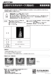
1392 02 ⁄ 2010 OPERATING INSTRUCTIONS, MOUNTING & INSTALLATION KLSW KLGF including mounting flange including mounting flange Duct airflow monitors, electronic, one- and two-step S+S stands for reliable control technology resulting from certified development and production while employing high-quality materials. Our products combine easy mounting & installation and precision you feel with long service life in the patented original design. Guaranteed made in Germany! PRECISION YOU FEEL. THE ORIGINAL. MADE IN GERMANY. Congratulations! You have bought a German quality product. MADE IN ANY GERM S+S REGELTECHNIK GMBH KLINGENHOFSTRASSE 11 90411 NUREMBERG ⁄ GERMANY PHONE+49 (0) 911 ⁄ 5 19 47- 0 FAX +49 (0) 911 ⁄ 5 19 47- 70 [email protected] www.SplusS.de RHEASREG ® KLSW including mounting flange RHEASGARD ® KLGF including mounting flange Duct airflow monitors, electronic, one- and two-step, with active ⁄ switching output The electronic airflow monitor RHEASGARD ® KLGF measures the flow velocity in m ⁄ s and converts the measurement signal into a standard signal of 0 - 10 V (relative) (flow measuring transducer). This flow sensor is optionally available with or without display. RHEASREG ® KLSW provided with a switching output (one-step or two-step) is designed as flow sensor ⁄ flow monitor. Fine adjustment of the upper range limit by the user is possible at a potentiometer. The airflow monitor ⁄ airflow sensor is applicable for monitoring or controlling airflows in ducts, at ventilators and dampers, for flow-dependent monitoring of humidifiers and electric heating registers according to DIN 57100, part 420, or for use in connection with DDC systems. KLSW - xx KLGF - 2 TECHNICAL DATA: Power supply:���������������������������������� 24 V AC ⁄ DC or 230 V AC +5 ⁄ -13 %, 50 … 60 Hz Output:��������������������������������������������� 1 or 2 potential-free relays (changeover contacts) 10 A, max. 2 kW or 0 - 10 V (relative, non-linear) Power consumption:����������������������� ca. 3 VA One-step: Operating range:����������������������������� 0.1… 30 m ⁄ s (adjustable) Sensitivity:���������������������������������������� 0.1… 30 m ⁄ s Two-step (KLSW - 5 ⁄ 6) : Operating range:����������������������������� 0.1…15 m ⁄ s (adjustable) Sensitivity:���������������������������������������� 0.1… 5 m ⁄ s Switching hysteresis:��������������������� ca. 1…10 % (adjustable) Start bridging:��������������������������������� ca. 15 …120 s (adjustable) Switch-off delay:������������������������������ ca. 2 … 20 s (adjustable) Max. sensor cable length:�������������� 50 m; avoid laying parallel with mains voltage-carrying lines, or use shielded cables KLGF-1 without display Ambient temperature:������������������� 0 °C …+ 60 °C at the device 0 °C …+ 80 °C medium Sensor:��������������������������������������������� sensor breakage protection, temperature-compensated Connecting head:���������������������������� plastic, material polyamide, 30% glass-globe-reinforced, colour pure white (similar RAL 9010) Dimensions: 108 x 73.5 x 70 mm 72 x 64 x 39.4 mm (KLGF -1 without display only) Cable gland:������������������������������������� M 16, including strain relief Protective tube:������������������������������ metal, Ø 10 mm, nominal length NL = 140 mm Process connection: ���������������������� by mounting flange (included in the scope of delivery) Electrical connection:��������������������� 0.14 - 1.5 mm2, via screw terminals on circuit board Protection class:����������������������������� I (according to EN 60 730) at UB = 230 V III (according to EN 60 730) at UB = 24 V Protection type:������������������������������ IP 65 (according to EN 60 529) Standards:��������������������������������������� CE-conformity, EMC directive 2004 ⁄ 108 ⁄ EC, low-voltage directive 73 ⁄ 23 ⁄ EEC KLSW - 5 ⁄ 6 Schematic diagram 3 4 5 Alarm 6 7 8 Flow Switch-off delay Hysteresis 15s 120s 2s 20s 1% 10% Flow velocity min. max. BN 11 BK 10 BU 9 Sensor KLSW 5/6 Switch-on delay 1 (L+) 2 (N-) Schematic diagram KLSW - 3 ⁄ 4 Connecting diagram KLGF -1 ⁄ 2 Dimensional drawing KLSW - xx KLGF - 2 KLGF - 1 with display Dimensional drawing KLGF - 1 without display Type ⁄ WG1 Relay Type (Steps) Power Supply Output KLGF - 1 with display Dimensional drawing KLSW - 3 1 1 (compact) 230 V AC 1 x changeover contact (1-step) KLSW - 4 1 1 (compact) 24 V AC ⁄ DC 1 x changeover contact (1-step) KLSW - 5 2 2 230 V AC 2 x changeover contact (2-step) KLSW - 6 2 2 24 V AC ⁄ DC 2 x changeover contact (2-step) KLGF -1 - 1 (compact) 24 V AC ⁄ DC 0 -10 V (relative) KLGF - 2 - 1 (compact) 230 V AC 0 -10 V (relative) KLGF -1 - Display Optional: Automatic reset (without reset button) KLSW is delivered with a manual reset button as a standard. MF KLGF 1, KLGF 2 Technical data Type KLGF 1 KLGF 2 Operating voltage 24 V AC ⁄ DC 230 V AC Voltage tolerance + 10% + 5% i - 13% II II mains voltage existing mains voltage existing Item No. Overvoltage category Signal indication, voltage Power consumption max. max. 2 VA max. 2 VA - 20..+ 60°C - 20..+ 60°C 0..10 V (Ra =10 kOhm) relative 0..10 V (Ra =10 kOhm) relative + ⁄ - 10% MW +⁄- 10% MW ± 1% ± 1% Device ambient temperature Signal output flow in V Accuracy of output signal Reproducibility of output signal Media temperature range 0..+ 70°C 0..+ 70°C Temperature gradient 15 K ⁄ min 15 K ⁄ min adjustable via potentiometer adjustable via potentiometer Switchpoint Measuring range 0,1- 30 m ⁄ s 0,1- 30 m ⁄ s Measuring sensor built-in built-in Immersion depth 130 mm 130 mm Process connection PG7, mounting flange PG7, mounting flange Sensor material MS 58, nickel-plated MS 58, nickel-plated 10 bar 10 bar Protection type, enclosure IP 65 IP 65 Protection type, sensor IP 67 IP 67 II II Pressure resistance Contamination class Connection Enclosure dimensions 3 terminals, 2.5 mm2 3 terminals, 2.5 mm2 L=72 mm; W=64 mm; H=39.4 mm L=72 mm; W=64 mm; H=39.4 mm Test mark Accessories 0 0 mounting flange mounting flange Reference conditions: Inlet zone >10 x DN, outflow zone >5 x DN, laminar flow: air at 0 °C and 1.013 bar Mounting conditions KLGF 1 To avoid malfunctions, the following points must be observed: •The sensor tip should be placed in the centre of the duct or pipe if possible. The gaseous medium must fully pass through the cross-hole in the sensor shaft. •Use marking as a mounting aid. •In pipes laid vertical, flow direction should be from bottom up. •Ensure free inlet zone = 5 x D upstream from the sensor and 3 x D = outflow zone downstream from the sensor. •Screw in flow monitor by the hexagon at the sensor enclosure only. •This flow monitor can be used in any mounting position. KLGF 1, KLGF 2 ATTENTION! Trained specialist personnel must execute connection and putting in operation! Mains connection (L, N) is to be made via fused breaker switch with the usual cutout elements. Electric installation must on principle follow the general VDE directives (VDE 0100, VDE 0113, VDE 0160). Putting in operation – KLGF 1 ⁄ 2 Specialist personnel must execute connection and putting in operation! For putting in operation and calibrating the devices, the following procedure is practical: • Install flow monitor and make electrical connections according to mounting and installation instructions. •Switch on mains voltage, then turn on nominal flow. •At the KLGF 1 ⁄ 2, calibrate the respective output signal to the nominal flow using the »Amplification« potentiometer. For example, for nominal flow 5 m ⁄ s, calibrate signal output U to 5 V, for nominal flow 10 m ⁄ s, calibrate signal output U to 10 V •The flow meter is now operable. The device is now set to monitoring function. What to do when air flow monitor doesn‘t function Problem KLGF... doesn‘t function at all KLGF... doesn‘t recognize flow KLGF... shows changed responding behaviour Cause Solution No or incorrect mains voltage connected Sensor is not installed correctly Sensor is highly contaminated by the medium Check mains voltage and connection Check mounting conditions Clean Sensor carefully with water In the KLGF 1 ⁄ 2, sensor and control device form one compact unit. The sensor tube is also used for mounting. With KLGF 1 ⁄ 2, the relative intensity of flows can be indicated and evaluated. At the device, you can adapt the analog output range to the existing flow conditions by setting the desired output voltage (max.10 V) at maximum flow. Intended use Series KLGF 1 ⁄ 2 flow monitors are used for monitoring flow rates in gaseous media within specified technical data limits. Main fields of application are air conditioning and ventilation technology in sectors of building and facility automation. Mode of operation Series KLGF 1 ⁄ 2 flow monitors function on the calorimetric principle and provide a 0...10 V output signal analog to flow velocity. KLSW 3, KLSW 4 Series KLSW electronic airflow monitors are used for monitoring ventilators and dampers, for flow-dependent monitoring of humidifiers and electric heating registers according to DIN 57100, part 420, or for applications in connection with DDC systems. Function: After applying operating voltage (green LED lighting) and building up the desired flow velocity (red LED lighting) within the starting delay, the »Alarm« relay is activated and the subsequent device is released. Sometimes detrimental heating ⁄ humidifying without air discharge is so avoided. In case the necessary airspeed is not reached within the starting delay, the »Alarm« relay drops out. Contacts 12 ⁄ 11 close. When preset flow rate is reached again, the »Alarm« relay is reactivated. Contacts 11 ⁄ 14 close. By pressing the Reset button, the device is reset to its initial condition. TECHNICAL DATA Type Item No. Operating voltage Voltage tolerance Overvoltage category Signal indication, voltage Power consumption max. Device ambient temperature Signal output flow Current ⁄ contact load Switching function at flow Signal indication at flow Start bridging Start bridging indication Media temperature range Temperature gradient Switchpoint Measuring range Response time Measuring sensor Immersion depth Process connection Sensor material Pressure resistance Connection Protection type, enclosure Protection type, sensor Contamination class Enclosure dimensions Test mark Accessories (included) KLSW 4 KLSW 3 24V AC ⁄ DC ± 10% II green LED 2 VA - 20..+ 60°C 230 V ⁄ AC ± 10% II green LED 4 VA - 20..+ 60°C 1 changeover contact 250 V AC, 6 A, 1.5 kVA relay activated yellow LED 1 changeover contact 250 V AC, 6 A, 1.5 kVA relay activated yellow LED 60 s (via jumper) yellow LED 60 s (via jumper) yellow LED - 10...+ 80°C 15 K ⁄ min adjustable via potentiometer 0.1 - 30 m ⁄ s 1...10 s - 10...+ 80°C 15 K ⁄ min adjustable via potentiometer 0.1 - 30 m ⁄ s 1...10 s built-in 130 mm PG7, mounting flange MS 58, nickel -plated 10 bar built-in 130 mm PG7, mounting flange MS 58, nickel -plated 10 bar 5 terminals, 2.5 mm2 IP 65 IP 67 2 L=108 mm, W=72.5 mm, H=70 mm 5 terminals, 2.5 mm2 IP 65 IP 67 2 L=108 mm, W=72.5 mm, H=70 mm 0 0 mounting flange 10 mm mounting flange 10 mm Start bridging Jumper plugged = start bridging active for ca. 60 s, yellow LED »Time« lighting Jumper not plugged = start bridging inactive KLSW 5, KLSW 6 Mounting of sensor (F9) Mount sensor so that airflow is passing through the cross-hole in the sensor shaft. The wire length between sensor and monitoring device should not exceed 100 m. If sensor cable is laid in one duct together with current-carrying lines (e.g. supplying motors or solenoid valves), we recommend shielding sensor wires. The sensor must be connected with the flow monitor according to the connecting diagram. Interchanging connections will cause malfunction. Setting (all types): The flow velocity to be monitored is preset at the »Flow rate« potentiometer on the circuit board inside the device (red LED lighting). The red LED goes out as soon as flow velocity drops below the preset value and does not rise back to the value to be maintained within the preset switch-off delay. Set trimmer »Hysteresis« so that according to flow conditions (smooth or turbulent flow), restless switching behaviour is avoided and without variation spread getting too wide. Reduce or cut off flow generation for checking flow monitoring. The red LED extinguishes and the “Flow“ output relay drops out while the »Alarm« relay is activated. By pressing the Reset button, the device is reset to its initial condition. Devices with start bridging (KLSW 5 ⁄ 6) Applications exist, where ventilator motors need a long run-up period so that the required flow (depending on the setting of the device‘s sensitivity) will be available not until run-up is completed. During run-up, the flow monitor could switch to failure. On the KLSW 6, adjustable start bridging (2 – 120 s) is integrated, bridging the start-up phase. During this period, output relay »Flow« is activated, the red LED »Air flow« lights up. Thereby, the device acts as if flow would exist so that switch-off is avoided. We recommend to switch on devices with start bridging together with the flow generator, as bridging time is only activated at the time mains voltage is switched on. When monitoring device is switched on earlier, the internal time might have expired before flow is strong enough. TECHNICAL DATA Type KLSW 6 KLSW 5 Operating voltage 24 V AC ⁄ DC 230 V ⁄ AC Voltage tolerance ± 10 % ± 10 % green LED green LED Item No. Signal indication, voltage Power consumption max. Device ambient temperature Signal output flow Current ⁄ contact load Switching function at flow Signal indication at flow Start bridging Start bridging indication Switch-off delay Media temperature range Temperature gradient Switchpoint Measuring range Measuring sensor Protection type, enclosure Protection type, sensor Connection Enclosure dimensions Test mark 2 VA 4 VA - 20...+ 60 °C - 20...+ 60°C 1 changeover contact 1 changeover contact 250 V AC, 10 A, 2.5 kVA 250 V AC, 10 A, 2.5 kVA relay activated relay activated yellow LED yellow LED adjustable via potentiometer (15 – 120 s) adjustable via potentiometer (15 – 120 s) - - adjustable via potentiometer (2 – 20 s) adjustable via potentiometer (2 – 20 s) - 10...+ 80°C - 10...+ 80°C 15 K ⁄ min 15 K ⁄ min adjustable via potentiometer adjustable via potentiometer 0.1 – 15 m ⁄ s 0.1 – 15 m ⁄ s F9 F9 IP 65 IP 65 IP 67 IP 67 11 terminals, 2.5 mm 5 terminals, 2.5 mm L=108 mm; W=72,5 mm; H=70 mm L=108 mm; W=72,5 mm; H=70 mm 0 0 Notes Our “General Terms and Conditions for Business“ together with the “General Conditions for the Supply of Products and Services of the Electrical and Electronics Industry“ (ZVEI conditions) including supplementary clause “Extended Retention of Title“ apply as the exclusive terms and conditions“. Furthermore, the following points must be observed: - These instructions shall be read before installation and putting in operation and all directions contained herein shall be followed! - These devices must only be connected to safety extra-low voltage and under dead-voltage condition. To avoid damages and errors at the device (e.g. by voltage induction), shielded cables shall be used, laying parallel with current-carrying lines is to be avoided, and the EMC directives must be adhered to. - This device shall only be used for its intended purpose. Respective safety regulations issued by the VDE, the states, their control authorities, the TÜV and the local energy supply company must be observed. The buyer has to ensure adherence to the building and safety regulations and has to avoid all dangers of any kind. - We do not assume any warranties or liabilities for faults or damages arising or resulting from improper use of this device. - Consequential damages caused by a fault in this device are excluded from warranty or liability. - These devices must be installed by authorized qualified personnel only. - The technical data and connecting conditions shown in the mounting and operating instructions delivered together with the device are exclusively valid. Deviations from the catalogue representation are not explicitly mentioned and are possible in terms of technical progress and continuous improvement of our products. - In case of any modifications made by the user, all warranty claims are forfeited. - This device must not be installed close to heat sources (e.g. radiators) or be exposed to their heat flow. Direct sun irradiation or heat irradiation by similar sources (powerful lamps, halogen spotlights) must absolutely be avoided. - Operating this device close to other devices that do not comply with EMC directives may influence functionality. - This device must not be used for monitoring applications, which solely serve the purpose of protecting persons against hazards or injury, or as an EMERGENCY STOP switch for systems or machinery, or for any other similar safety-relevant purposes. - Dimensions of enclosures or enclosure accessories may show slight tolerances on the specifications provided in these instructions. - Modifications of these records are not perwithted. - In case of a complaint, only complete devices returned in original packing will be accepted. These instructions must be read before installation and putting in operation and all notes provided therein are to be regarded! CHARACTERISTICS KLGF Errors and technical changes excepted. © Copyright by S+S Regeltechnik GmbH · Reprints, in part or in total, are only permitted with the approval of S+S Regeltechnik GmbH.