1
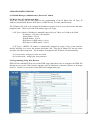
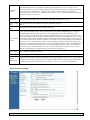
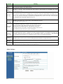
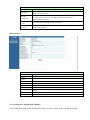
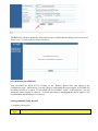
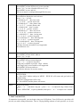
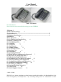
User Manual
Model: IP Phone 202
Table of Contents
Recommendation:
Please read the entire manual before using your new IPPH202.
1 Welcome 2
2 What Is In the Package
2
3 Product Overview .........................................................................................................2
3.1 Key Features ..............................................................................................................2
3.2 Hardware Specifications ...........................................................................................3
4 Installation
4
5 Basic Operations
4
5.1 Get Familiar with Function Keys
4
5.2 Dialing or Making Calls
4
5.2.1 Two dialing modes
4
5.2.2 Call Hold
5
5.2.3 Call Flash
5
5.2.4 Call Transfer
5
5.2.4.1 Blind Transfer
5
5.2.4.2 Attended Transfer
5
5.3 Receiving Calls
6
5.4 Call Features
6
6 Programming IPPH 202
7
6.1 Default Manager (Administrator) Password
7
6.2 Major Sets of Configuration Data 7
6.3 Programming Using Web Browser
7
6.3.1 Determine your VoIP device’s IP address
8
6.3.2User Programming and Configuration
8
6.3.3 Configuration Options and Explanations
9
6.3.4 Saving the Configuration Changes
17
6.3.5 Rebooting the IPPH 202
18
6.4 Programming Using Keypad 19
7 Test Your Setup
21
8 Technical Support Contacts
21
1. WELCOME
IPPH 202 is an internet telephone set that features superb audio quality, rich functionalities, high
level of integration, and compactness. By converting analog voice for transmission over the
internet, the IP Phone 202 allows users with broadband internet connections to make calls to and
from anywhere in the world. The IPPH 202 is fully compatible with SIP industry standard and can
interoperate with many other SIP compliant devices and software on the market.
2. WHAT IS IN THE PACKAGE
The IPPH 202 package contains:
1) One IPPH 202 VoIP phone
2) One IPPH 202 phone handset
3) One universal power supply
4) One Ethernet cable
3. PRODUCT OVERVIEW
3.1 Key Features
• Supports SIP 2.0
• Supports TCP/UDP/IP, RTP/RTCP, HTTP, ARP/RARP, ICMP, DNS, DHCP, NTP, TFTP
protocols
• DHCP support for LAN or Cable modem
• PPPoE support for ADSL or Cable modem
• Supports IP address dynamic (DHCP) system
• Supports multi-method NAT traversal and anti-virus crossing
• Compliant with ITU-T standard and DTMF form and check
• Supports codecs G.723.1 (5.3K/6.3K), G.729A/B, iLBC, G.726, G.728, and wide-band G.722
sound coding and decoding
• Supports dynamic sound check VAD (Voice Activity Detection), CNG (Comfort Noise
Generation), Line Echo Cancellation (G.168), and AGC (Automatic Gain Control)
• Dynamic sound technology with sound quality as good as traditional telephones
• Advanced Digital Signal Processing (DSP) to ensure superb hi-fidelity audio quality
• Support standard voice features such as Caller ID Display or Block, Call Waiting, Hold,
Transfer Forward, FLASH, in-band and out-of-band DTMF (RFC2833), Dial Plans, off-hook
auto dial, configurable emergency dialing (e.g., 911), early dial, click-to-dial
• Advanced adaptive jitter buffer control, packet delay & loss concealment technology
• Support multi-net construction
• Auto–manual indication
• Built-in world clock auto time display
• Has single or dual network ports (10 BaseT)
• Support dial code regulation based on E.164
• Support TFTP remote upgrade
• English language IE setting
• Dialed, received number check
• Speed dial function
• Emulate telephone dialing
• Easy volume adjustment
• IP-to-IP and point-to-point communication
• HiFi low delay net sound communication
• Local IP number, local number check
• Instant plug and play
• Full duplex hands-free speakerphone superior frequency
• Call forwarding, call waiting, call hold, call transfer, redial, call log, volume control, voice
mail with indicator
3.2 Hardware Specification
The table below lists the hardware specification of IPPH 202.
Model
IPPH 202
WAN interface
PC interface
Product Color
Universal Switching Power Supply
1 x RJ45 10 Base-T
Available for IPPH 202B
Almost Black or Grey
Input: 100-240VAC 50-60 Hz
Dimension
Output: +9VDC, 600mA,
UL certified
23cm (L)
All Package Weight
Operation Temperature
Storage Temperature
Humidity
19cm (W)
10cm (H)
1.01kg
0 – 40° C, 32° –104° F
-30° –65° C, -22°– 149° F
10 - 95%
4. INSTALLATION
1) Insert power adapter into back of the phone and connect it to a power outlet.
2) Connect internet cable from back of the phone (WAN Port) to broadband modem, router,
hub, or switch.
3) For IPPH 202B, connect internet cable from back of the phone (PC Port) to a PC.
Warning: Please do not use a different power adapter. Using other power adapter may
damage the IPPH 202 and will void the manufacturer warranty.
5 BASIC OPERATIONS
5.1 Get Familiar with Function Keys
Keypad Key
0 - 9, *(.), #
+
_
MENU
CALLED
CALLERS
MSG
HOLD
Function(s)
To input: numbers, *(.), #
Scroll to next menu/submenu selection, or lower the volume of the
loudhailer
Scroll to previous menu/submenu selection, or rise the volume of
the loudhailer
Enter menu mode
Show the phone number that has been called out
Show the phone number that has been called in
Get the voice message or other messages
Hold the present call for the moment
TRANSF
CONF
FLASH
MUTE/DEL
REDIAL
SPEAKER
Memory Key M1M10
Transfer the present call to another number
Conference call for three sides
Used to switch between two lines
Delete the call history, voice message, etc.
Dial the last called number
Enter the hand-free mode
Under Development
5.2 Dialing or Making Calls
5.2.1 Two dialing modes:
Ordinary dialing mode (4 ways):
1. Pick the up handset or press the “SPEAKER” button.
2. Press the REDIAL button to dial the Dial the last called number.
3. View the CALLED history and choose to redial.
4. View the CALLER history and choose to redial.
IP address dialing mode:
1. Press “MENU” button to view the local IP address.
2. Dial the IP address and press “#” to start calling
5.2.2 Call Hold
While in conversation, pressing the “Hold” button will put the remote end on hold.
Pressing the “Hold” button again will release the previously Hold state and the bidirectional media
will resume.
5.2.3 Call Flash
Assuming that call party A and party B are in conversation. Party A wants to speak to party C or if
there is another incoming call:
1. Party A presses FLASH to get a dial tone.
2. Party A then dials party C’s number then #. Party A and party C now are in conversation.
3. By pressing FLASH button, Party A can choose to have conversation with B or C.
5.2.4 Call Transfer
5.2.4.1 Blind Transfer
The user can transfer an active call to a third party without announcement.
Assuming that call party A and party B are in conversation. Party A wants to transfer party B to
party C:
1. Party A presses TRANSF to get a dial tone.
2. Party A then dials party C’s number then #.
3. Party A then press REDIAL. A quick confirmation tone if the transfer has been successful.
Party B and party C now are in conversation.
4. Party A can hang up or make another call.
5.2.4.2 Attended Transfer
The user can transfer an active call to a third party without announcement.
Assuming that call party A and party B are in conversation. Party A wants to transfer party B to
party C:
1. Party A presses Flash to get a dial tone.
2. Party A then dials party C’s number then #.
3. If the call is answered, press “flash” to complete the transfer operation
4. if the call is not answered, pressing “flash” button to resume the original call.
5.2.5 3-Way Conference Call Assuming that call party A called party B, and now they are in
conversation. Party A wants to let party C to attend the conversation:
1. Party A presses CONF to get a dial tone.
2. Then press party C’s number then # (or wait for 4 seconds). Party A and party C now are in
conversation.
3. Party A presses CONF again, now the 3 parties are all in conversation.
Note: The server needs to support this function for this feature or the phones to work.
5.3 Receiving Calls
When phone rings from incoming calls and to receive the incoming calls, pick up the receiver or
press the “SPEAKER” button. After picking up the call, to switch from hand free mode to receiver
mode, just pick up the receiver and begin talking; the speakerphone will be deactivated. To switch
from receiver mode to hand free mode, press down the “SPEAKER” button while placing the
receiver back to resting location. Now the speakerphone is activated and you may continue
speaking without receiver.
5.4 Call Features
Following table shows the new call features of IPPH 202.
Key
Call Features
*70
Do Not Disturb. When someone call you, “do not disturb” busy tone will be heard.
To use this feature, pick up the handset and dial “*70”. It will be cancelled when you hang up.
*72
Unconditional Call Forward. To use this feature, dial “*72” and get the dial tone. Then dial the forward
number and “#” for a dial tone, and then hang up.
*73
Cancel Unconditional Call Forward. To cancel “Unconditional Call Forward”, dial “*73” and get the
dial tone, then hang up.
*90
Busy Call Forward. To use this feature, dial “*90” and get the dial tone. Then dial the forward number
and “#” for a dial tone, and then hang up.
*91
Cancel Busy Call Forward. To cancel “Busy Call Forward”, dial “*91” and get the dial tone, then hang
up.
*92
Delayed Call Forward. To use this feature, dial “*92” and get the dial tone. Dial the forward number and
“#” for a dial tone and then hang up.
*93
Cancel Delayed Call Forward. To cancel this feature, dial “*93”, get the dial tone, and then hang up.
Flash/Hook
When in conversation, this action will switch to the new incoming call if there is a call waiting
indication. When in conversation without an incoming call, this action will switch to a new channel to
make a new call.
6 PROGRAMMING IPPH 202
6.1 Default Manager (Administrator) Password: admin
6.2 Major Sets of Configuration Data
There are 8 major sets of data related to the programming of the IP Phone 202: IP Type, IP
Address, Subnet Mask, Router, DNS Server1, DNS Server2, Account, and Password.
The IP Phone 202 needs to be assigned an IP address in order for it to access the internet and make
telephone calls. There are 2 kinds of IP address types (IP Type):
1) IP Type 0 (Static): IP address is manually entered by you. There are 5 fields to be filled:
IP Address: 192.168.0.160 (default)
Subnet Mask: 0.0.0.0
Default Router: 0.0.0.0
DNS Server1 (DNS using): 0.0.0.0
DNS Server2 (DNS spare): 0.0.0.0
2) IP Type 1 (DHCP): IP address is dynamically assigned by router, if any, at the location,
thereby allowing it to access the internet and make calls. Plug the IP Phone 202 into the router
using the LAN port connection. The IP address is assigned to the IP Phone 202 automatically.
3) User Account: Assign your own user name
4) User Password: Assign your own password
6.3 Programming Using Web Browser
IPPH 202 has embedded Web server and HTML pages that allow users to configure the IPPH 202
through an easy-to-use Web browser interface such as Microsoft’s Internet Explorer or Netscape
browser. Below is a screen shot of the IPPH 202 configuration page:
6.3.1 Determine your VoIP device’s IP address.
On the IPPH202 (while handset is up)
push the “MENU” key to obtain the phone’s IP address, which will show on the LCD
screen. If the IP address is all “0”s, then your VoIP device does not have internet
connection. Please go back to step 1 and check your installation before proceeding.
6.3.2 User Programming and Configuration
From your web browser, the IPPH 202 will show the following login screen:
Password: admin
6.3.3 Configuration Options and Explanations
After a correct password is entered in the login screen, the embedded web server inside the IPPH
202 will show the configuration page, which is explained in details below:
SIP Settings:
SUPER USER OPTIONS PAGE
SIP Settings
Meaning
Options
SIP
Server
Address
Outbound Proxy
SIP User ID
SIP Outbound Proxy Server’s URL or IP address
SIP service subscriber’s User ID
Account ID
SIP service subscriber’s Authenticate ID. Can be identical to, or different from, SIP User ID
Authentication
Password
SIP service subscriber’s account password(for security, the password does not display)
Name
Use DNS SRV:
SIP service subscriber’s name which will be used for Caller ID display
Default is No. If set to Yes, then the client will use DNS SRV for server lookup
User ID is Phone
Number
If the IPPH 202 has an assigned PSTN telephone number, then this field should be set to “Yes”.
Otherwise, set it to “No”. If “Yes” is set, a “user=phone” parameter will be attached to the “From”
header in SIP request message to SIP server
SIP Registration
This parameter controls whether the IPPH 202 needs to send REGISTER messages to the proxy
server. The default setting is “Yes”.
Unregister on
Reboot
Default is “No.” If set to “Yes”, then the SIP user will be unregistered on reboot.
Register
Expiration
This parameter allows the user to specify the time frequency (in minutes) the IPPH 202 refreshes its
registration with the specified gatekeeper/SIP server. The default interval is 60 minutes (or 1 hour).
The maximum interval is 65535 minutes (about 45 days).
Local SIP Port
This parameter defines the local SIP port the IPPH 202 listens and transmits signals. The default
value is 5060.
Gatekeeper's / SIP Server’s URL or IP address
Local RTP port
This parameter defines the local RTP-RTCP port pair the IPPH 202 will listen and transmit signals.
It is the base RTP port for channel 0. When configured, channel 0 will use this port _value for RTP
and the port_value+1 for its RTCP; channel 1 will use port_value+2 for RTP and port_value+3 for
its RTCP. The default value is 5004.
Use
Port
When set to “Yes”, this parameter will force random generation of both the local SIP and RTP
ports. This is usually necessary when multiple IPPH 202 are behind the same NAT.
Random
Keep Connected
Interval
This parameter defines whether the IPPH 202 NAT traversal mechanism will be activated or not. If
activated (by choosing “Yes”) and a STUN server address is also specified, then the IPPH 202
will automatically follow the STUN client specifications. Under this mode, the embedded STUN
client inside the IPPH 202 will attempt to detect if there is a (and type of) firewall/NAT it is sitting
behind through communication with the specified STUN server. If the detected NAT is a Full
Cone, Restricted Cone, or a Port- Restricted Cone, the IPPH 202 will attempt to use its mapped
public IP address and port in all of its SIP and SDP messages. If the NAT Traversal field is set to
“Yes” with no specified STUN server, the IPPH 202 will periodically (every 20 seconds) send a
blank UDP packet (with no payload data) to the SIP server to keep the “hole” on the NAT open.
This parameter specifies how often the IPPH 202 sends a blank UDP packet to the SIP server in
order to keep the “hole” on the NAT open.
Use NAT IP:
Proxy-Require
NAT IP address used in SIP/SDP message. Default is blank.
SIP Extension to notify SIP server that the unit is behind the NAT/Firewall.
Send DTMF
This parameter controls how DTMF events are transmitted. There are 3 ways: In-Audio which
means DTMF is combined in audio signal (not very reliable with low-bit-rate codec), via RTP
(RFC2833), or via SIP INFO.
DTMF Payload
Type
This parameter sets the payload type for DTMF using RFC2833
Send
Anonymous
If this parameter is set to “Yes”, the “From” header in outgoing INVITE message will be set to
anonymous, essentially blocking the Caller ID from displaying.
Send
Event
This parameter allows users to control whether to send a SIP NOTIFY message indicating that the
phone’s Flash key has been pushed, or just to switch to the voice channel when users press the
Flash key.
NAT Traversal
Flash
Audio Settings:
Audio Settings
Options
Meaning
Preferred
Codec
The IPPH 202 supports up to 7 different Codec types including G.711 G.723.1, G.726, G.728,
G.729A/B, iLBC. Users can configure Codecs in a preference list that will be included with the same
preference order in SDP message. The first Codec in this list can be entered by choosing the
appropriate option in “Choice 1”. Similarly, the last Codec in this list can be entered by choosing the
appropriate option in “Choice 7”.
G723 Rate:
This defines the encoding rate for G723 codec. By default, 6.3kbps rate is chosen.
iLBC Frame
Size:
iLBC Payload
Type:
This defines the size of the iLBC codec frame. The default setting is
20ms.
This defines payload time for iLBC. Default value is 97.
Voice Frames
per TX
This field contains the number of voice frames to be transmitted in a single packet. When setting this
value, the user should be aware of the requested packet time (used in SDP message) as a result of
configuring this parameter. This parameter is associated with the first codec in the above codec
Preference List or the actual used payload type negotiated between the 2 conversation parties at run
time. For example, if the first codec is configured as G723 and the “Voice Frames per TX” is set to be
2, then the “ptime” value in the SDP message of an INVITE request will be 60ms because each G723
voice frame contains 30ms of audio. Similarly, if this field is set to be 2 and if the first codec chosen
is G729 or G711 or G726, then the “ptime” value in the SDP message of an INVITE request will be
20ms. If the configured voice frames per TX exceeds the maximum allowed value, the IPPH 202 will
use and save the maximum allowed value for the corresponding first codec choice. The maximum
value for PCM is 10(x10ms) frames; for G726, it is 20 (x10ms) frames; for G723, it is 32 (x30ms)
frames; for G729/G728, 64 (x10ms) and 64 (x2.5ms) frames, respectively.
Layer 3 QoS
This field defines the layer 3 QoS parameter, which can be the value used for IP Precedence or DiffServ or MPLS. Default value is 48.
Layer 2 QoS
This contains the value used for layer 2 VLAN tag. Default setting is 0.
Silence
Suppression
This controls the silence suppression/VAD feature of G723 and G729. If set to “Yes”, when a silence
is detected, small quantity of VAD packets (instead of audio packets) will be sent during the period of
no talking to make the connection feel more "natural". If set to “No”, this feature is disabled.
Phone Features Settings:
Phone Features Settings
Options
Early Dial
Dial
Plan
Prefix
No Key
Entry
Timeout
Use # as
Dial Key
Meaning
Default is “No”. Use only if proxy supports 484 response
Sets the prefix added to each dialed number
Default is 4 seconds. This is the time lapse after entering a phone number for the IPPH 202 to begin
completing your call.
This parameter allows users to configure the “#” keyto be used as the “Send / Enter” (or “Dial”) key. If
set to “Yes”, pressing this key will immediately trigger the sending of dialed numbers entered thus far.
In this case, this key is essentially equivalent to the “(Re)Dial” key. If set to “No”, this “#”key will then
be included as part of the dial string to be sent out.
Auto
Answer
Voice Mail
Default is NO. When set to yes the phone will automatically pick up
the call and turn the speaker on.
Voice Mail
UserID
This parameter defines the User ID (or extension number) of a 3rd
party voice mail system where the user may have an account. By
defining this Voice Mail extension, when the user presses the
“Message” button on the phone, an INVITE message will be sent to
that extension to allow the user to retrieve messages.
Off-hook
Auto-Dial
Enable Call
Features
Disable Call
Waiting
Default
Ring Tone
This parameter allows users to configure a User ID or extension number to be automatically dialed upon
off-hook. Please note that only the user part of a SIP address needs to be entered here. The IPPH 202
will automatically append the “@” and the host portion of the corresponding SIP address.
Default is “No”. If set to “Yes”, Call Forwarding & Do-Not-Disturb are supported locally
Default is “No”.
The user can setup up one number on each of the ring tones 1, 2 and 3. When a call is received from one
of these numbers, the respective ring tone will be generated.
Other Settings:
Other Settings
Meaning
Options
Firmware
Upgrade via
TFTP server
Firmware
Upgrade via
HTTP server
The IP of TFTP server needs to be configured. If it is non-zero or not blank, the IP phone will
attempt to retrieve new configuration file or new code image from the specified tftp server at boot
time. It will make up to 3 attempts before timeout and then it will start the boot process using the
existing code image in the Flash memory. If a tftp server is configured and a new code image is
retrieved, the new downloaded image will be verified and then saved into the Flash memory. Be
careful when the TFTP is in progress (the phone back light on LCD screen will be up). Do NOT
interrupt the process (especially the power supply) otherwise might cause the device dead. Be
patient as in some network this process will take up to 15 minutes.
The URL for the HTTP server used for firmware upgrade and configuration via HTTP. For
example, http://upgrade.myVoIPservice.com:6688/IPPH202 Here “:6688” is the specific TCP port
that the HTTP server is listening to, it can be omitted if using default port 80. Note: Auto Upgrade
has to be set to “Yes” to enable HTTP upgrade.
Auto Upgrade
Choose Yes to enable HTTP upgrade and provisioning. In “Check for new firmware every ___
days” field, enter the number of days to check the HTTP server for firmware upgrade or
configuration.
NTP Server
This parameter defines the URI or IP address of the NTP server which the IP phone will use to
synchronize the current date/time.
SUBSCRIBE
for MWI
Default is “No”. When set to “Yes” a SUBSCRIBE for Message Waiting Indication will be sent
periodically.
FXS Impedance
Selects the impedance of the analog telephone connected to the Phone port.
Lock Keypad
Update
If this parameter is set to “Yes”, the configuration update via keypad is disabled.
Debug
Server Address
This parameter defines the URI or IP address of the Debug server.
Debug Level
Default is “None”. Choose the debug level you want when using this function.
Super Password
Default is “Admin”. This contains the password to access the Advanced Web Configuration page.
This field is case sensitive.
Network Settings
Network Settings
Meaning
Options
Dynamically
Assigned IP
If DHCP mode is enabled, then all the field values for the Static IP mode are not used (even though
they are still saved in the Flash memory) and the IP phone will acquire its IP address from the first
DHCP server it discovers on the LAN it attaches to. PPPoE account settings can be configured here
too if the user is using DSL/ADSL connection. Users can specify DNS server manually by entering
DNS server’s IP address.
Static IP
If Static IP mode is selected, then the IP address, Subnet Mask, Default Router IP address, DNS
Server 1 (primary and mandatory), DNS Server 2 (secondary and optional) fields will need to be
configured. These fields are reset to zero by default.
Other settings:
Other Settings
Meaning
Options
Time Zone
This parameter controls how the displayed date/time will be adjusted according
to the specified time zone.
Daylight
Savings Time
This parameter controls whether the displayed time will be daylight
savings time or not. If set to Yes, then the displayed time will be 1
hour ahead of normal time.
Date Display
Format
Basic
User
Password
This parameter controls the date display format.
This contains the password to access the Basic Web Configuration page. This
field is case sensitive.
Device Status
fields
MAC Address
WAN IP
Address
Software Version
System Up Time
Registered
PPPoE Link Up
NAT
NAT Mapped IP
Other Status
Device Status
Meaning
The device ID, in HEX format. This is very important ID for ISP troubleshooting.
This field shows WAN port IP address.
This field shows the software version.
This shows system up time since last reboot.
This shows whether the unit is registered to service provider’s server.
This shows whether the PPPoE is up if connected to DSL modem.
This shows what kind of NAT the BudgeTone is behind if it is not in oper
interne.
WAN side public IP if connected to LAN of a SOHO NAT router.
Please refer to the page displayed.
6.3.4 Saving the Configuration Changes
Once a change is made, users should click on the “SaveSet” button in the Configuration page.
The IPPH 202 will then display the following screen to confirm that the changes have been saved.
Please wait 5 seconds and then reboot the device.
6.3.5 Rebooting the IPPH 202
You can reboot the IPPH 202 by clicking on the “Reboot” button after each update to the
configuration page. Alternatively, you can reboot by unplugging the power supply of the IPPH 202
and then powering it on again. If your IPPH 202 ever becomes “stuck” or un-responsive, you can
unplug the power supply to reboot it. Frequent rebooting by unplugging the power supply is not
recommended and should not be necessary.
6.4 Programming Using Keypad
Configure with keypad
Menu
Item
Menu function(s)
1
Show“ 1 dhcp on”
Press“ 1 dhcp off”as the current option
Press MENU and enter the menu mode
Press “+”or“-”to choose
Press MENU to save or exit
Restart to be effective
2
Show “ 2 IP Addr”
Press MENU to show the current IP address
If DHCP is OFF enter new IP address
Press“+”or“-” to exit
Press MENU to save or exit
Restart to be effective
3
Show“ 3 SubNet”
Press MENU to show subnet address
If DHCP is OFF enter new subnet address
Press“+”or“-”to exit
Press MENU to save or exit
Restart to be effective
4
Show“ 4 routEr ”
Press MENU to show router/gateway address
If DHCP is OFF, enter router/gateway address
Press“+”or“-”to exit
Press MENU to save or exit
Restart to be effective
5
Show“ 5 dnS ”
Press MENU to show DNS address
If DHCP is OFF, enter new DNS address
Press“+”or“-”to exit
Press MENU to save or exit
Restart to be effective
6
Show“ 6 tFtP ”
Press MENU to show tFtP address
Enter new tFtP address
Press“+”or“-”to exit
Press MENU to save or exit
7
Show “[7] G-711u 2”
Press MENU to show current codec
Press ‘+’ or ‘-’ to view all codec options
1 “ - G-711A 2”
2 “ - G-722 2”
3 “ - G-723 1”
4 “ - G-726 2”
5 “ - G-728 8”
6 “ - G-729 2”
7 “ - iLBC 1”
Press 1 to 9 to choose the frame number
Press MENU to exit.
No need to restart
8
Show“ 8 SIP SP-1”
Press MENU to show SIP server/ service provider
Press“+”or“-”to view all usable SIP server (1-9)
Press MENU to save and exit
SIP server must be configured through Web browser
9
Show “[9] codE rEL”
Press Menu to display the code releases
Press ‘+’ or ‘-’ to view
1 “b 2004-06-12” – date: boot code
2 “ 1. 0. 0.18” – version: boot code
3 “P 2004-06-21” – date: phone code
4 “ 1. 0. 5. 3” – version: phone code
5 “c 2004-05-06” – date: vocoder
6 “ 1. 0. 0. 6” – version: vocoder
7 “h 2004-06-17” – date: web server
8 “ 1. 0. 0. 36” – version: web server
9 “1r 2004-05-12” – date: 1st ring tone
10 “ 1. 0. 0. 0” – version: ring tone
11 “2r 2004-05-12” – date: 2nd ring tone
12 “ 1. 0. 0. 0” – version: ring tone
13 “3r 0000-00-00” – date: 3rd ring tone
14 “ 0. 0. 0. 0” – version: ring tone
(all show 0 means not usable or not supported)
Press Menu to exit
10
Show“ 10 Phy Addr”
Press MENU to show MAC address
Press“+”or“-”to exit
11
Show “[11] ring 0”
Press MENU to hear current ring tone
Press ‘+’ or ‘-’ to choose ring tones
4 ring tones available at present ring0 default
ring1,ring2.ring3 are not usable or not supported
Press MENU to choose and save
Be effective directly. No need to restart.
Show “ -- rESEt --”,
ATTENTION:
A> Enter MAC address and press MENU IPPH 202 will restart and get back to all
default setting.
All former configuration will be lost.
B> Press MENU and the phone will restart.
Others
When in the mode:
• Press‘+’ or ‘-’ and show“ ring [4] ”, press ‘+’ or ‘-’ to adjust the ring volume form 0
to 7
• Press “SPEAKER” , or pick up handset, then press ‘+’ or ‘-’ to adjust voice volume.
7. TEST YOUR SETUP
If connection is successful, you can begin using your VoIP phone. Your VoIP service provider will
provide you with calling instructions. Due to varying dialing schemes of each provider, we do not
have specific dialing to recommend.
8. TECHNICAL SUPPORT CONTACTS
e-mail: [email protected]