1
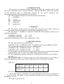
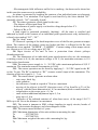
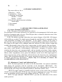
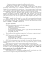
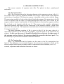
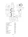
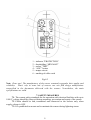
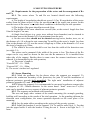
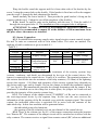
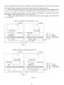
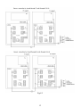
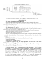
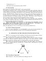
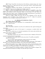
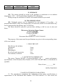
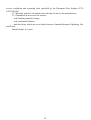
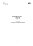
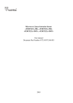
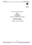
Microwave Intrusion Linear Sensor
“Forteza-300/500”
“Forteza-300/500T”
User manual
Document Part Number 4372-43071246-003
2003
CONTENTS
1. Introduction ................................................................................................. 3
2. Purpose ........................................................................................................ 3
3. Specifications .............................................................................................. 3
4. Sensor Components ..................................................................................... 5
5. Sensor Structure & Operation ..................................................................... 5
5.1. Sensor Principle of Operation .................................................................. 5
5.2. Adjustment, Control and Indication Parts ................................................ 5
5.3. Sensor Operation ...................................................................................... 6
6. Sensor Construction .................................................................................... 7
6.1. Rx Construction........................................................................................ 7
6.2. Tx Construction ........................................................................................ 7
7. Safety Measures .......................................................................................... 9
8. Mounting Procedure .................................................................................... 10
8.1. Requirements for the preparation of the sector and the arrangement
of Rx and Tx .................................................................................................... 10
8.2. Sensor Mounting ...................................................................................... 10
8.3. Sensor Connection.................................................................................... 11
9. Preparation of the Sensor for the Operation & Adjustment ........................ 14
9.1. Sensor Preparation for its Operation ........................................................ 14
9.2. Adjustment of Tx and Rx ......................................................................... 14
9.3. Rx threshold ............................................................................................. 15
9.4. Check of Sensor Operation ...................................................................... 15
10. Operation of the Sensor with the Deflector .............................................. 15
11. Check of Technical State........................................................................... 16
11.1. Check of Sensor Operation .................................................................... 16
11.2. Servicing................................................................................................. 16
12. Troubleshooting Guide .............................................................................. 17
13. Storage ....................................................................................................... 18
14. Transportation ........................................................................................... 18
Certificate ........................................................................................................ 18
2
1. INTRODUCTION
The present user manual contains information about the operation of the local
microwave intrusion sensors “Forteza-300/500”, “Forteza-300/500T” (below the sensor).
In this document there is information required for the correct operation (use,
transportation, storage and maintenance) of the sensor.
The following abbreviations are used in the present document:
Tx - transmitter
Rx - receiver
MK - mounting kit
SU - supply init
JB - junction box.
2. PURPOSE
2.1. The purpose of the sensor is to protect the perimeter sectors and to detect an
intruder crossing at his full height or bent (crawling) through this sector.
2.2. The sensor is intended for continuous round-the-clock outdoor operation at an
ambient temperature:
“FORTEZA-300/500”
-45˚…+65˚C
“FORTEZA-300/500T” -50˚…+60˚C
and relative humidity up to 98% at the temperature +35 С.
3. SPECIFICATIONS
3.1. The sensors have four modifications:
“FORTEZA-300”, “FORTEZA-300T”, “FORTEZA-500” and “FORTEZA-500T”.
The recommended length of a sector for modifications:
“FORTEZA-300”, “FORTEZA-300T” – 10…300m
“FORTEZA-500”, “FORTEZA-500T” – 10…500m.
3.2. The height of the detection zone generated by the sensor at the maximum length
of the detection zone is 1,8m in the center of the perimeter ground.
3.3. The configuration and the dimensions of the detection zone are given in fig.3.1.
and table 3.1.
The detection zone is a volumetric part of a sector that being the very specialty in
the kind of detection, and any movement within this sector will generate an alarm.
Table 3.1.
Length of a
sector, m
500
300
250
150
50
Width of the
3,5
2,7
2,5
1,9
1,0
zone, m
3.4. The sensor generates an alarm when:
- An intruder crosses a detection zone (perpendicularly to the axis) at a speed of 0,
1…10 m/sec at his full height or bent (crawling through) with the minimum detection
probability of 98 %;
- RC signal is given on Tx;
3
- Electromagnetic field influences on Rx for its masking. An alarm can be absent but
in this case the sensor saves its availability.
An alarm is generated by breaking the contacts of an individual point opt electronic
relay for the time 3 sec minimum. This signal is sent from Rx by the wires marked “NC”
(normally closed); “NC” (normally closed).
3.5. The sensor generates a fault signal in the case:
- The absence of the signal from Tx.
- In the absence of power supply or when the voltage drops below 9 V.
- Failure of Rx or Tx.
A fault signal is generated constantly (latching) till the same is rectified and
indicated by break in the contacts of an individual point optoelectronic relay indicated by
colored wires marked “NC”; “NC”.
3.6. No “dead” zones.
3.7. Removal/ opening of the back inspection cover of the Rx unit generate a tamper
alarm. The contacts of the tamper circuit are broken and this is reflected at the Rx unit
through the wires marked “TAMPER”, “TAMPER”. Contacts rating of this tamper circuit
are: current up to 0,2A at voltage up to 80 VDC.
3.8. Input circuits of Rx and Tx have a protection from electric pickups
(thunderstorm too).
3.9. The dimensions of an individual point optoelectronic relay are: the maximum
switching current is 0,1A; the maximum voltage is 50 V; the maximum resistance is 110
Ohm in the closed status.
3.10. The sensor power supply is: 9…30 VDC with a maximum pulsation of 0,02 V
maximum. The maximum current consumption is 0,04A.
3.11. The sensor operation can be tested by applying 5…30 VDC signal at the RC
on the Tx unit. The RC is marked as “RC” (remote control) input of the transmitter. The
duration of this test signal is 1…3 sec.
3.12. The sensor doesn’t generate an alarm when:
- rain, snow, thick fog
- solar radiation
- the influence of wind at a speed of 30 m/sec. maximum
- moving of the objects in the DZ (detection zone) of 3m from Rx or Tx of the
objects with the linear dimensions of 0,2 m maximum (birds or small animals)
- irregularities on the sector up to ± 0, 3m
- snow without additional adjustment up to 0, 5 m
- grass up to 0, 4 m
influence of the radiated emission of ultra short waves of the range 150-175
MHz up to 40 Vat on the distance 6 m maximum.
3.13. The sensor is immune to EMI: voltage impulses in supply circuits, breaks of
main supply, electrostatic discharges, and electromagnetic fields.
3.14. The sensor mean lifetime is 8 years.
3.15. Maximum dimensions of the units without a mounting kit, mm:
Tx
- 835*240*240
Rx
- 835*240*240.
3.16. Maximum weight of the units with a mounting kit, kg:
Tx
- 5;
4
Rx
- 5.
4. SENSOR COMPONENTS
The sensor delivery kit is:
1. Receiver – 1 item
2. Transmitter - 1 item
3. Mounting kit including:
Bracket – 2 items
Buckle – 4 items.
4. Kit of tools and accessories including:
Alarm cable
5. User manual
6. Package
5. SENSOR STRUCTURE & OPERATION
5.1. Sensor Principle of Operation
5.1.1. The sensor is a bistatic microwave device.
The principle of the sensor operation is to generate an electromagnetic field in the space
between a transmitter and a receiver. This field provides a volumetric detection zone in the
form of a long ellipsoid of rotation.
5.1.2. An intruder crossing a detection zone causes changes of the field. All changes
of this field are recorded. The signal passes through the amplifier and is compared with the
value thresholds according to the algorithm. If the signal’s change on Rx input is
provoked by a person passage, Rx generates an alarm breaking output contact of the relay.
The signal on Rx input can be changed under the influence of other factors: height and
weight of the intruder, place of the sector’s intersection, its relief, speed of the movement.
5.1.3. The signal on Rx input can be changed under the influence of other factors:
rain, grass, small animals, electromagnetic interference, swinging of branches, gates
entering the detection zone commensurable with an intruder movement. Other reasons,
e.g. location of extensive constructions, objects in the detection zone or near from it like as
fences, walls, irregularities, snow, grass can influence on the level of Rx input signal. In
theses cases because of big reflections and interference the detection zone configuration
jumps. Multi thresholds algorithm of the sensor operation permits to decrease the number
of alarms provoked by interference. That’s why it is necessary to observe the
recommendations in the subsection 8.1!
5.2. Adjustment, Control and Indication Parts
5.2.1. An alarm generates the values of the Rx thresholds. An explorer establishes
them during the operation with the controller of the thresholds “MIN-MAX”. The
thresholding is realized by the main rotation of resistor axis with screwdriver. In this case
the thresholds will change from minimum (MIN) to maximum (MAX) value.
5.2.2. The input signal is controlled with the tester on the socket that is marked
"TEST" (test jack).The more TEST the more Rx input signal and vise versa. The sensor
keeps its operation with the range of the voltage values too: TEST 0,1 - 4,8 V.
5.2.3. The light indicator “PROTECTION” provides the indication of the sensor
mode operation:
5
- Continuous luminescence means the standby state of the sensor;
- The indicator’s switching off for 3 sec means the alarm generation.
Pressing the button "AGC" on Rx it is possible a broken glow of the indicator
“Protection”. To decrease the power consumption, the indicator “Protection” goes out after
10 min of the sensor operation in the standby state if there were no pressures on the button
“AGC”, the turn of the levels controller, transfer of the sensor in the alarm mode. In this
case the indicator disconnection doesn’t influence on the state of the relay contacts.
5.2.4. During Rx and Tx adjustment on the maximums of the antennas directional
diagrams, the amplifier is transferring from the mode of the adjustment with a big time
constant to the mode with a small time constant by pressing the button “AGC” (automatic
gain control) on Rx. In this case an express setup of the amplifier takes place on the
standby state.
5.2.5. A “normally closed” tamper loop is provided to prevent unauthorized opening
of the back panel of the Rx unit. In the operating condition the tamper circuit’s contacts
are closed, during the back panel opening they are broken. The alarm cables circuits
marked “TAMPER”; “TAMPER” are broken too.
5.3. Sensor Operation
5.3.1. The sensor operation provides the following suite:
Preparation of the sector
Signal cables and power supply laying
Tx and Rx installation
Sensor connection (connection of power supply and loops of intruder alarms)
Alignment of Tx and Rx antennas
Setup of Rx thresholds.
The principles and the methods of the operations’ performance are given in items 810.
5.3.2. The sensor has the following operating regimes:
Standby state (contact breaking)
Alarm signal (open condition)
Tamper state of Rx (the contacts of the tamper circuit are opened).
5.3.3. The receiver control device realizes the receipt and the indication of alarms.
The sensor operates with the receiving- control devices providing the check of the relay
contacts.
5.3.4. During the operation the remote control checks the sensor efficiency.
The constant voltage 5…30 V for 1…3 sec is realized on the Tx wire marked “RC”. The
beaming of Tx is interrupted for the time of the signal “RC” operation. Then Rx generates
an alarm. In such a way the signal generation after the signal “RC” confirms the
sensor operation and the running order of the loop.
The user determines the control periodicity.
5.3.5. Besides there it is necessary to check periodically the technical state of the
sensor and its servicing. Periodicity of the checks is given in item 11.
6
6. SENSOR CONSTRUCTION
The sensor consists of separate units (Rx, Tx) placed in dust-, splash-proof
enclosures.
6.1. Rx Construction
6.1.1. Rx Construction and its fastening elements to the support are given in fig. 6.1.
The carrier of Rx 1unit is a parabolic antenna. The exciter is fixed inside of this antenna
(in the focus of parabola). The detection camera is installed on this exciter with the flange.
The processing module is fixed on the sidewall inside the antenna. Rx connection to the JB
or SU is realized with the cable 14 coming through the cable entry. Rx is fixed on the
support with the bracket 9 and buckles 8. First the bracket is fixed on the support, and then
Rx is fixed to the bracket with the nut 11. The access to the controls, adjustment,
indication elements and clamps for the connection of the terminal element is open when
the cover 10 is removed. The adjustment and indication elements located under the cover
10 are given in fig. 6.2.
The main operating position of Rx is given in fig.6.1. In the cases when it is
impossible to fix Rx at the left from the support, it can be fixed on the right from the
support. In this case the screws 2 should be installed in two holes in the upper part of
the antenna, and two holes of the antennas should be opened in the lower part. They
are necessary to prevent the condensate inside the antennas.
6.2. Tx Construction
6.2.1. Tx construction and its bracket are the same as the Rx construction (see
fig.6.1). The difference is in internal elements: the microwave generator is fixed on the
exciter instead of the detection camera which is connected to the modulator; cover 10,
controls, adjustment and indication elements are absent.
7
1-receiver (transmitter)
2-screw M4×8
3- screw M6×8
4- washer 6
5-round support (tube)
6-nut
7- washer 8
8-buckle
9-bracket
10-cover
11-nut
12-spring washer 12
13-washer 12
14-cable
15-corrugated tube
16-pressure seal
1 item
2 items
2 items
2 items
1 item
2 items
2 items
2 items
1 item
1 item
1 item
1item
1 item
1 item
1 item
1item
Fig.6.1
8
1 – indicator "PROTECTION"
2 – thresholding “MIN-MAX”
3 – socket "TEST"
4 – “AGC” button
5 – tamper circuit
6 – marking of cable cords
Fig.6.2
Note. Dear user! The manufacturer of the sensor constantly upgrades their quality and
reliability. That’s why in some lots of sensors one can find design modifications
unspecified in the documents delivered with the sensors. Nevertheless, the main
specifications are valid.
7. SAFETY MEASURES
7.1. The current safety standards for the operation with electrical facilities with up to
1000 V voltage should be observed during mounting, prevention and repair of the sensor.
7.2 Cables should be laid, terminated and connected to the sockets only when
supply voltage is OFF.
7.3. It is prohibited to mount and to maintain the sensor during lightning storm.
9
8. MOUNTING PROCEDURE
8.1. Requirements for the preparation of the sector and the arrangement of Rx
and Tx
8.1.1. The sector where Tx and Rx are located should meet the following
requirements:
a) The height of irregularities should not exceed +0,3m. If irregularities of the sector
surface from the plane exceed +0,3m, the specifications of the sensor can worsen. In this
case the issue of the sensor’s use under these conditions is defined by the trial operation.
b) The height of the grass should not exceed 0,4m;
c) The height of the snow should not exceed 0,9m; at the sector’s length less than
50m the height is 1m max;
d) Single fixed objects (e.g. posts, trees without lower branches) can be situated in
the detection zone at the distance of 0,5 m minimum from the axis;
e) On the sector there should not be situated moving leaves, bushes, trees, etc. at
the distance of ±1,0 m from the axis connecting Tx and Rx at the sector’s length less than
50m; at the distance of ±2,2 m at the sector’s length up to 250m; at the distance of ±3 m at
the sector’s length up to 500m;
f) The width of the sector should be not less than the width of the detection zone
(see table 3.1);
The sensor can be mounted if the width of the sector is less. The alarm of the Rx
output can be very small or absent. In this case the Rx antenna or Tx is installed from
other side of the support. Besides there in some cases the sensors interference can be
reduced. It is determined by the trial operation;
g) The sector’s length is:
“Forteza-300” - 10…300m;
“Forteza-500” - 10…500m;
h) The sector’s incline isn’t regulated.
8.2. Sensor Mounting
8.2.1. Mark the perimeter for the places where the supports are mounted. To
organize the continuous boundary of the protection, the joint Tx and Rx installation of
adjacent perimeter grounds isn’t permitted. The right units’ installation of adjacent
perimeter grounds is Tx and Tx, Rx and Rx.
8.2.2. Mount the supports. It is recommended to use metal or asbestos-cement tube
as supports of 150…200mm diameter. As the sensor hasn’t “dead” zones two Tx (Rx)
units can be installed on every support of adjacent perimeter grounds.
8.2.3. The supports are mounted with concreting.
The user can apply other variants of the sensor mounting (for example guarding,
building wall) according to the results of the trial operation. As the guarding deforms the
detection zone configuration, the sensor operation depends on the exact place of its
mounting.
8.2.4. Lay the main cables according to the project of the security systems.
8.2.5. Install the brackets 9 on the supports 5 of Tx and Rx units (fig.6.1). For that
join the upper buckle 8 with the bracket 9 using the nut 6. Screw a nut tight for 2…3
turns.
10
Wrap the buckle round the support and fix it from other side of the bracket by the
screw 3 using the nearest hole on the buckle. If the bracket is fixed not well on the support
pass the screw 3 through the hole shortened the buckle.
Install similarly the lower buckle 8. Then provide the good bracket’s fixing on the
support with the nut 6. Unbend or cut off the surpluses of the buckles.
8.2.6. Install Tx and Rx units on the brackets with the nuts 11. Pass the cable 14
through the corrugated tube 15. The installation of the corrugated tube is obligatory.
ATTENTION! To reduce the level of electromagnetic interference induced on
supply lines it is recommended to mount SU at the distance of 300 m maximum from
the place where the sensors are installed.
8.3. Sensor Connection
8.3.1. Switch ON the necessary supply units, signal circuits, remote control circuits.
Rx and Tx units are connected with its own alarm cables. The wires are marked. The
marking of cable conductors is given in table 8.1.
Table 8.1
Rx
Tx
Circuit
Color
Purpose
Circuit
Color
Purpose
“+”
white
“+”
white
Supply voltage
Supply voltage
“-“
brown
“-“
brown
Remote control
“NC”
yellow Individual point
“RC”
green
+5…30 V
relay contacts
“NC”
pink
“TAMPER” green
Contacts of
tamper circuit
“TAMPER” grey
8.3.2. The type and the nominal of the terminator of the security systems loop
(resistor, condenser, and diode) are determined by the type of the control device. The
sensor is connected to the control device. Usually it is a resistor. The nominal resistance of
this resistor should take into the resistance of the relay contacts (≈30 Ohm) of the lightning
circuit (this resistor - 100 Ohm) and resistence of the security systems loop (depends on
the chosen cable type and its length). Rx has the clamps to install the terminator marked
“T” (see fig.6.2). The manufacturer provides the clamps shortening with the jumper. If the
terminator is installed not on the clamp but in other place, the jumper isn’t removed and
provides the integrity of the security systems loop.
8.3.3. The contacts of the tamper circuit (“TAMPER”) of Rx can be connected to
the receiving-control device by the separate loop. In this case the user receives the
information of the opening of the Rx terminal cover with the separate signal. The second
variant: the individual point relay is switched ON in series with the contacts of the
individual relay. In this case an alarm will be generated when:
- the individual point relay functions;
- the opening of the Rx terminal cover on one channel of the control device.
8.3.4. There is the scheme (see fig.8.1) of the sensor connections using the junction
box “Barrier-JB”. The contacts of the tamper circuit will be switched on in series with the
relay contacts. The sensor receives a signal from remote control (RC) when an additional
11
button is installed in the room. It is possible to install one button on some sensors. In this
case the button pressing checks the sensors operation of all group sensors.
There is the model scheme of the sensor connection using the storm protection unit
“LGU-4” (see fig.8.2). During the mounting of the storm protection unit “LGU-4” it is
necessary to install them near Rx (Tx) units. The best installation is instead of the JB (if
the quantity of the switched circuits is 8 items max).
There is the model scheme of two sensors connection to the supply unit “PSU 24-0,
7” (see fig.8.3).
Fig.8.1
12
Fig.8.2
13
Fig.8.3
9. PREPARATION OF THE SENSOR FOR THE OPERATION AND
ADJUSTMENT
9.1. Sensor Preparation for its Operation
Check the right connection of supply circuits and output circuits of the sensor.
Take away the cover of Rx and connect the terminator to the clamps “T” after
removing previously the jumper.
9.2. Adjustment of Tx and Rx
9.2.1. Tx and Rx antennas are adjusted at the height of 0,5m.The height’s count is
realized from the lower antenna to the ground (fig.6.1).
To provide the sensor availability, it is necessary to adjust Tx and Rx antennas.
9.2.2. The alignment includes the following procedure:
- Loosen the nuts 6 and 11 (see fig.6.1);
- Revolve Tx (Rx) antennas with the brackets round the support, incline the antennas
vertically, then adjust them. Use the aiming cleat situated on the sidewall of the
antennas;
- Tighten the nuts 6;
9.2.3. Adjust exactly Tx and Rx antennas from the sector’s angle.
- Switch on the sensor;
- Open the cover 10 of Rx (fig.6.1);
- Connect the voltmeter with the alarm cable from the sensors kit to the socket
“TEST” of Rx to check the signal’s level received by Rx;
- Press the button “АGC”. Pressing it and stooping in turn Tx and Rx vertically exact
the maximum indicated value of voltmeter.
- Ease the button “АGC”.
- Check the value of “TEST” voltage as a result of the adjustment. If “TEST” voltage
is less than 1,2 V, it is necessary to repeat the alignment vertically and horizontally
for more exact adjustment. If the voltage controlled by the voltmeter is over 4,5V (on
short sectors), it is recommended to make the desalignment of Rx and Tx
upwards at a small angle so the voltage does not exceed 4,5V. Don’t desalign Rx
and Tx down or towards. The sensor keeps its operation using “TEST” voltage
0,1…4,8V. The boundary values of 1,2V and 4, 5V during the adjustment are
recommended for the resource of the signal level to provide a long operation;
14
- Tighten the nuts 11;
- Disconnect the tester from the socket “TEST”.
9.3. Rx threshold
9.3.1. Mount the controller “MIN-MAX” in the position MAX.
Thresholds are adjusted when a person crosses a protected sector uniformly along the
whole length. It is necessary to go out from the DZ of 1-2 m for Rx calming (otherwise the
results of the previous passage will influence on the following). When the sensor generates
alarms, “PROTECTION” indicator becomes to dim for 3 sec. The following passage can
be done after the switching ON of the indicator “PROTECTION”. If the signal is not
generated during the investigator passage, the controller “MIN-MAX” will be turned on
one-two points counter-clockwise and the alignment will be continued.
Do some check passes along the whole length of the sector especially in the “problem”
sector places: in hollows, hills, next to the trees branches situated in the detection zone. If
it is necessary regulate the detector thresholds.
Align the thresholds very attentively as “decreasing” the thresholds a lot of
false alarms can be taken place because of some interference; “increasing” the
thresholds some sensors omissions appear in its operation.
When the adjustment is over, it is necessary to close the Rx terminal cover.
9.4. Check of Sensor Operation
After the sensor adjustment it is recommended to carry out its trial operation for
2…3 days to reveal and eliminate possible errors of mounting and adjustment.
10. OPERATION OF THE SENSOR WITH THE DEFLECTOR
10.1. If it is necessary to create breaking of the detection zone the sensor “Forteza300/500” (“Forteza-300/500T”) can be used with the deflector (fig.10.1).
10.2. A metal sheet (its dimensions no less than 1*1m) is used as a deflector. During
mounting the deflector should be adjusted at the angle of the place and have reliable
fastening to exclude its vibration when it is windy because it can cause false alarms.
10.3. During the operation through the deflector the total length of the detection
zone does not exceed 150m for “Forteza-300” (“Forteza-300T”) and 200m for “Forteza500” (“Forteza-500T”).
deflector
Tx
Rx
Fig.10.1
10.4. Procedure of Operation
10.4.1. Mount Tx, Rx and the deflector according to item 8.2.
15
10.4.2. Align Tx and Rx in the direction of the deflector with the aiming cleat. Open
the Rx terminal cover 10 and connect the tester to the socket “TEST” with the alarm cable.
Switch on supply voltage.
Changing the position of the deflector, Tx and Rx units, obtain the signal on the
socket “TEST”. Carry out exact alignment according to item 9.2.
10.4.3. To define the optimal position of the deflector it is possible to use a laser
pointer. Place a mirror on the deflector (the plane of the mirror should be parallel to the
plane of the deflector) and fix the pointer (keep it) in the center of Tx unit. Direct the
pointer beam on the mirror center. Changing the position of the deflector it is necessary to
obtain the beam from the pointer to be in the center of Rx.
Switch on supply voltage and carry out the exact alignment of Rx, then the
alignment of Tx according to the methods given in item 9.2. Adjust the operation
thresholds of Rx according to methods given in item 9.3.
11. CHECK OF TECHNICAL STATE
11.1. Check of Sensor Operation
11.1.1. During the sensor exploitation it is recommended to check remote control
(“RC”) 1…3 times in a day.
11.2. Servicing
11.2.1. The sensor should be served by the technicians after special training and
instruction.
11.2.2. During the service of the sensor it is necessary to conduct check and
preventive works.
11.2.3. Every month carry out external examination of the sensor units and the state
of the sector where Tx and Rx are installed.
It is necessary to check:
the absence of dust, dirt, snow and ice from the side of radiation of Rx and Tx
antennas and clean them if it is necessary;
the absence of outside objects in the sector where Tx and Rx are installed.
11.2.4. Every quarter:
carry out all the works specified as works carried out every month;
check the state of the cables and cable connections.
11.2.5. During seasonal works it is controlled the height of the grass. If the height of
the grass is over 0,3m the grass should be cut or removed by another method.
11.2.6. If the height of snow changes, false alarms can be generated because of the
decrease of the signal at the input of the receiving unit. In this case it is necessary to
remove snow or to change the height of Tx and Rx antennas installation.
After the height of the antenna mounting is changed, they should be aligned. The
thresholds should be adjusted according to the procedure given before.
16
12. TROUBLESHOOTING GUIDE
List of possible troubles is given in table 12.1.
Table 12.1
Trouble
Possible Cause
Repair
1. The
1. Communication
Check the cable
receivingline is broken.
integrity and the
control
accuracy of its
device
connection.
constantly
Restore the
generates an
communication
alarm
line.
2. The protective
Replace the
device in the supply
protective device.
unit is blown.
3. The sensor
Align Tx and Rx
alignment is
antennas.
disturbed.
4. Tx fails.
Replace Tx.
5. Rx fails.
Replace Rx.
2. False
1. Moving branches
Inspect the sector
alarms of the are in a detection
and remove
sensor
zone and they cause
interference
alarms.
factors.
2. High grass is in the
sector.
3. Snow blanket is
higher than one
specified in the
manual and this
reduces an input
signal.
4. Animals circulate
in the sector.
5. The Rx thresholds Check the
are too low.
accuracy of the
Rx thresholds
setting.
3. The
1. Rx thresholds are
Check the
sensor does too high.
accuracy of the
not generate
Rx thresholds
alarms when
setting.
an intruder
crosses the
sector.
2. The alignment is
Align Tx and Rx
17
Trouble
Possible Cause
disturbed.
Repair
antennas.
13. STORAGE
13.1. The sensors should be stored in the package in warehouses at an ambient
temperature +5 С…+30 С and relative humidity 85% maximum.
During storage the influence of hostile environment should be prevented.
14. TRANSPORTATION
14.1. Packaged sensors can be transported by any transport (if by plane – in
pressurized modules) if they are transported in covered cars, holds or covered bodies they
can be transported at the distance up to 10 000 km.
The boxes should be placed to prevent their shifting or fall in case of jolts and
blows.
Microwave Intrusion Linear Sensor
“Forteza-300/500”
“Forteza-300/500T”
Certificate
Document Part Number 4372-43071246-003
The purpose of the sensor and its specifications are given in the corresponding items
of the user manual.
1. DELIVERY KIT
The delivery kit includes:
Transmitter
Receiver
Mounting kit
Kit of tools and accessories
User manual, certificate
1 item
1 item
1 kit
1 kit
1 item.
2. ACCEPTANCE CERTIFICATE
The sensor “Forteza-300/500” (“Forteza-300/500T”) № ______meets performance
specifications of the Document Part Number 4372-43071246-003 and it is considered as
operable.
Date of issue _________200 .
Quality department
3. MANUFACTURER’S GUARANTEES
3.1. The manufacturer guarantees the conformity of the sensor specifications to
requirements of the Document Part Number 4372-43071246-003 if a user meets the
18
service conditions and operating rules specified by the Document Part Number 437243071246-003.
3.2. Warranty period is 18 months since the date of sale by the manufacturer.
3.3. Guarantees do not cover the sensors:
- with broken guarantee stamps;
- with mechanical failures,
- and also those which are out of order because of natural disasters (lightning, fire,
and flood).
Mean lifetime is 8 years.
19