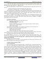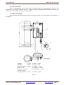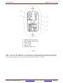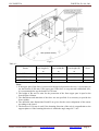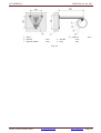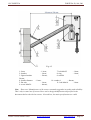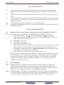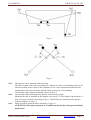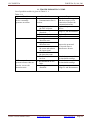
1
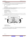
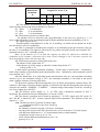
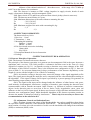
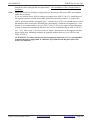
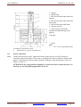
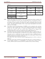
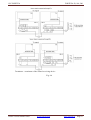
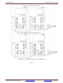
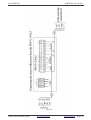
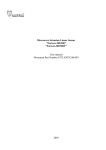
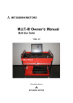
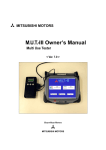
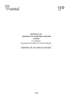
JSC FORTEZA FORTEZA-50, 100, 200 Local Microwave Protective Detector “Forteza-50” “Forteza-100” “Forteza-200” Description Manual & Service Instruction 4372-43071246-065 ТО 2012 Please visit our internet sites: www.forteza.com www.forteza.eu Page 1 JSC FORTEZA FORTEZA-50, 100, 200 CONTENTS 1. Introduction ..................................................................................................................... 3 2. Purpose ............................................................................................................................ 3 3. Specifications .................................................................................................................. 3 4. Detector Components ...................................................................................................... 5 5. Detector Structure & Operation ...................................................................................... 5 5.1. Detector Principle of Operation ................................................................................... 5 5.2. Adjustment, Control and Indication Parts .................................................................... 5 5.3. Detector Operation ....................................................................................................... 6 6. Detector Construction ..................................................................................................... 6 6.1. Rx Construction............................................................................................................ 6 6.2. Tx Construction ............................................................................................................ 7 6.3. MK (mounting kit) ....................................................................................................... 7 7. Safety Measures……………………………………………………………….………. 12 8. Mounting Procedure…………………………………………………………………… 12 8.1. Requirements for the preparation of the sector and the arrangement of Rx and Tx ……………………………………………………………….. 12 8.2. Sensor Mounting………………………………………………….………………….. 12 8.3. Sensor Connection…………………………………………………………………… 15 9. Preparation of the Detector for the Operation & Adjustment……………………….... ..20 9.1. Detector Preparation for its Operation…………………………………………..…… 20 9.2. Adjustment of Tx and Rx ............................................................................................. .20 9.3. Rx threshold …… ........................................................................................................ 20 10. Check of Technical State............................................................................................... 21 11. Troubleshooting Guide .................................................................................................. 22 12. Storage ......................................................................................................................... 23 13. Transportation ............................................................................................................... 23 Certificate ............................................................................................................................ 24 Please visit our internet sites: www.forteza.com www.forteza.eu Page 2 JSC FORTEZA FORTEZA-50, 100, 200 1. INTRODUCTION The present description manual and service instruction contains information about the operation of the local microwave protective detectors “Forteza-200”, “Forteza-100”, “Forteza-50” (below the detector). In this document there is information required for the correct operation (use, transportation, storage and maintenance) of the detector. The following abbreviations are used in the present document: Tx - transmitter Rx - receiver. 2. PURPOSE 2.1. The purpose of the detector is to protect the perimeter sectors and to detect an intruder crossing at his full height or bent (crawling) through this sector. 2.2. The detector is intended for continuous round-the-clock outdoor operation at an ambient temperature 40ºC…+65С and relative humidity up to 98% at the temperature +35С. 3. SPECIFICATIONS 3.1. The recommended length of a sector for modifications: “Forteza-200” – 10…200 m “Forteza-100” – 10…100 m “Forteza-50” – 5…50 m 3.2. The configuration and the dimensions of the detection zone are given in fig.3.1. and table 3.1. The detection zone is a volumetric part of a sector that being the very specialty in the kind of detection, and any movement within this sector will generate an alarm. L Rx Tx h 0,85 m b 3 -5 m Axis of the Detection zone Fig.3.1. L- Length of a sector h- Height of detection zone b- Width of detection zone In fig.3.1 and table 3.1 the height (h) and the width (b) of the detection zone are given for the middle of the sector. Moving towards the receiver or transmitter these dimensions decrease evenly, given the geometry of positioning the receiver and transmitter. Table 3.1. Please visit our internet sites: www.forteza.com www.forteza.eu Page 3 JSC FORTEZA FORTEZA-50, 100, 200 Dimensions, maximum, m Length of a sector L, m 10 25 h 50 100 200 1,4 1,6 1,8 0,5 0,7 1,0 1, 5 2, 1 b 3.3. The distance recommended from the axis of the detection zone up to guarding, building walls and other nonmoving objects should be as follows: 80…200m - 1, 1 m minimum 25…80m - 0, 8 m minimum 10…25m - 0, 4 m minimum 3.4. The detector generates an alarm when: - An intruder crosses a detection zone (perpendicularly to the axis) at a speed of 0, 3…10 m/sec at his full height or bent (crawling through) with the minimum detection probability of 98 %; - RC signal is given on Tx; - Electromagnetic field influences on Rx for its masking. An alarm can be absent but in this case the detector saves its availability. An alarm is generated by breaking the contacts of an individual point opt electronic relay for the time 3 sec minimum. This signal is sent from Rx by yellow and pink colored wires marked “NC” (normally closed); “NC” (normally closed). Note. At the distance of 3-5 m from the supports on which Tx and Rx are installed, the probability of the intruder’s detection who is bent (crawls through) is 98 % because a person can move bent and pass below the detection zone. 3.5. The detector generates a fault signal in the case: - The absence of the signal from Tx - In the absence of power supply or when the voltage drops below 9 V. - Failure of Rx or Tx. A fault signal is generated constantly (latching) till the same is rectified and indicated by break in the contacts of an individual point optoelectronic relay indicated by yellow and pink colored wires marked “NC”; “NC”. 3.6. The dimensions of an individual point optoelectronic relay are: the maximum switching current is 0,1A; the maximum voltage is 50 V; the maximum resistance is 100 Ohm in the closed status (with the elements of storm protection). 3.7. Removal/ opening of the back inspection cover of the Rx unit generate a tamper alarm. The contacts of the tamper circuit are broken and this is reflected at the Rx unit through the green and grey colored wires marked “TAMPER”, “TAMPER”. Contacts rating of this tamper circuit are: current up to 0,2A at voltage up to 80 VDC. 3.8. The detector power supply is: 9…30 VDC with a maximum pulsation of 0,02 V maximum. The maximum current consumption is 35 ma at 24 VDC. 3.9. The detector operation can be tested by applying 5…30 VDC signal at the RC on the Tx unit. The RC is marked as “RC” (remote control) input of the transmitter. The duration of this test signal is 1…3 sec. 3.10. The detector doesn’t generate an alarm when: precipitations such as rain, snow, thick fog solar radiation the influence of wind at a speed of 30 m/sec. maximum moving of the objects in the DZ (detection zone) of 5 m from Rx or Tx of the objects with the linear dimensions of 0,2 m maximum (birds or small animals) irregularities on the sector up to ± 0, 3m snow without additional adjustment up to 0, 5 m grass up to 0, 3 m Please visit our internet sites: www.forteza.com www.forteza.eu Page 4 JSC FORTEZA FORTEZA-50, 100, 200 influence of the radiated emission of ultra short waves of the range 150-175 MHz up to 40 Vat on the distance 6 m maximum. 3.11. The detector is immune to EMI: voltage impulses in supply circuits, breaks of main supply, electrostatic discharges, and electromagnetic fields. 3.12. Input circuits of Tx and Rx are protected from electric pickup (electric storm too). 3.13. The detector mean lifetime is 8 years. 3.14. Maximum dimensions of the units without a mounting kit, mm: Tx - 211*130*105 Rx - 211*130*105 3.15. Maximum weight of the units with a mounting kit, kg: Tx - 1,2 Rx - 1,2. 4. DETECTOR COMPONENTS The detector delivery kit is: 1. Receiver – 1 item 2. Transmitter - 1 item 3. Mounting kit including: Bracket – 2 items Buckle – 4 items. 4. Kit of tools and accessories including: Alarm cable Key S8*10. 5. Description Manual & Service Instruction 6. Package. 5. DETECTOR STRUCTURE & OPERATION 5.1. Detector Principle of Operation 5.1.1. The detector is a bistatic microwave detector. The principle of the detector operation is to generate an electromagnetic field in the space between a transmitter and a receiver. This field provides a volumetric detection zone in the form of a long ellipsoid of rotation (see fig.3.1.). An intruder crossing a detection zone causes changes of the field. All changes of this field are recorded. There is the detection zone configuration in fig.3.1, there are given in table 3.1 its crosscuts dimensions for three performances of the detector dependency on the length of a sector with the height 0, 85 m of Rx & Tx mounting. 5.1.2. An intruder crossing a detection zone causes the change of the signal magnitude on Rx input. The signal passes through the amplifier and is compared with the value thresholds according to the algorithm. If the signal’s change on Rx input is provoked by a person passage, Rx generates an alarm breaking output contact of the relay. 5.1.3. The signal on Rx input can be changed under the influence of other factors: rain, grass, small animals, electromagnetic interference, swinging of branches, gates entering the detection zone commensurable with an intruder movement. Other reasons, e.g. location of extensive constructions, objects in the detection zone or near from it like as fences, walls, irregularities, snow, grass can influence on the level of Rx input signal. In theses cases because of big reflections and interference the detection zone configuration jumps. Multi thresholds algorithm of the detector operation permits to decrease the number of alarms provoked by interference. That’s why it is necessary to observe the recommendations in the subsection 8.1! 5.2. Adjustment, Control and Indication Parts 5.2.1. An alarm generates the values of the Rx thresholds. An explorer establishes them during the operation with the controller of the thresholds “MIN-MAX”. The thresholding is realized by the main rotation of resistor axis with screwdriver. In this case the thresholds will change from minimum (MIN) to maximum (MAX) value. Please visit our internet sites: www.forteza.com www.forteza.eu Page 5 JSC FORTEZA FORTEZA-50, 100, 200 5.2.2. The input signal is controlled with the tester on the socket that is marked "TEST" (test jack).The more TEST the more Rx input signal and vise versa. The detector keeps its operation with the range of the voltage values too: TEST 0,1-4,8 V. 5.2.3. The light indicator “PROTECTION” provides the indication of the mode operation of the detector: - Continuous luminescence means the standby state of the detector; - The indicator’s switching off for 3 sec means the alarm generation. 5.2.4. During Rx and Tx adjustment on the maximums of the antennas directional diagrams, the amplifier is transferring from the mode of the adjustment with a big time constant to the mode with a small time constant by pressing the button “AGC” (automatic gain control) on Rx. In this case an express setup of the amplifier takes place on the standby state. 5.2.5. A “normally closed” tamper loop is provided to prevent unauthorized opening of the back panel of the Rx unit. In the operating condition the tamper circuit’s contacts are closed, during the back panel opening they are broken. The circuits of alarm cables marked “TAMPER”; “TAMPER” (green and grey wires) are broken too. 5.3. Detector Operation 5.3.1. The detector operation provides the following suite: Preparation of the sector Signal cables and power supply laying Tx and Rx installation Detector’s connection (connection of power supply and loops of intruder alarms) Alignment of Tx and Rx antennas Setup of Rx thresholds. The principles and the methods of the operations’ performance are given in items 8-10. 5.3.2. The detector has the following operating regimes: Standby state (contact breaking) Alarm signal (open condition) Tamper state of Rx (the contacts of the tamper circuit are opened). 5.3.3. The receiver control device realizes the receipt and the indication of alarms. The detector operates with the receiver control devices providing the check of the relay contacts. 5.3.4. During the operation the remote control checks the detector efficiency. The constant voltage 5…30 V for 1…3 sec is realized on the Tx green wire marked “RC”. The beaming of Tx is interrupted for the time of the signal “RC” operation. Then Rx generates an alarm. In such a way the signal generation after the signal “RC” confirms the detector’s operation and the running order of the loop. The user determines the control periodicity. 5.3.5. Besides there it is necessary to check periodically the technical state of the detector and its servicing. Periodicity of the checks is given in item 11. 6. DETECTOR CONSTRUCTION 6.1. Rx Construction 6.1.1. The detector consists of separate units (Rx, Tx) placed in dust-, splash-proof enclosures. 6.1.2. Rx Construction and its fastening elements to the support are given in fig. 6.1. The carrier of the unit is base 4. Radio transparent enclosure 5 is glued to the base with sealing material. In the heel of the enclosure there are two holes preventing condensed fluid accumulation within the unit. The access to the controls, adjustment, indication elements and clamps for the connection of the terminal element is open when the cover 6 is removed. Rx is connected to the receiver control device with six wires cable 8. Rx is mounted on the support 1 using the bracket 2 and two bucles13. Mounting provides the rotation of the unit horizontally at angle +65 minimum; vertically: upward - at angle 30 minimum, downward – at angle 45 minimum (if the bolt 12 is eased). Location and marking of the clamps, controls, and adjustment and indication elements located under the cover 6 are shown in fig. 6.2. Please visit our internet sites: www.forteza.com www.forteza.eu Page 6 JSC FORTEZA FORTEZA-50, 100, 200 6.2. Tx Construction 6.2.1. Tx construction and its bracket are the same as the Rx construction (see fig.6.1). The difference is in internal elements: cover 6, clamps, controls, adjustment and indication elements are absent; three wire cables are used instead of cable 8. 6.3. MK (mounting kit) 6.3.1. Mounting kit includes two brackets and four buckles for the mounting on the support of Rx and Tx. 1-support - 1 item 2- bracket - 1 item 3- figured washer - 2 items 4-base -1 item 5-enclosure - 1 item 6-cover -1 item 7- corrugated tube - 1 item 8-cable - 1 item 9-ring - 1 item 10-nut M6 - 1 item 11-washer 6 -2 items 12-bolt M6*16 - 1item 13-buckle- 2items Fig.6.1 Please visit our internet sites: www.forteza.com www.forteza.eu Page 7 JSC FORTEZA FORTEZA-50, 100, 200 1 - indicator "PROTECTION" 2 – threes holding “MIN-MAX” 3 - socket "TEST" 4 – “AGC” button 5 - tamper circuit 6 - marking of cable cords Fig.6.2. Note. Dear user! The manufacturer of the detector constantly upgrades their quality and reliability. That’s why in some lots of detectors one can find design modifications unspecified in the documents delivered with the detectors. Nevertheless, the main specifications are valid. Please visit our internet sites: www.forteza.com www.forteza.eu Page 8 JSC FORTEZA FORTEZA-50, 100, 200 Fig.6.3 Table 6.1. Sensor Max detection zone length (L), m Max detection zone width (B), m Max detection zone height (H), m FORTEZA-200 100 1,5 1,5 FORTEZA-100 100 1,5 1,5 FORTEZA-50 40 1,0 1,0 Notes Notes. 1. If the upper part of the fence is protected with physical protection devices, it is necessary to use the bracket of 500 mm. If the upper part of the fence is not protected with barbed wire, it is recommended to use the bracket of 350 mm. 2. The height of Rx and Tx units for the protection of the fence upper part is equal to the fence height ±100mm. 3. The dimensions and materials of the fence are not specified. It is necessary to provide the fence rigidity. 4. The detection zone dimensions B and H are given for the correct alignment of the sensor according to the item 9. 5. The bracket of 120 mm is used if the beaming direction of the unit is perpendicular to the support plane or if the beaming direction is within the angle range 90 ± 40. Please visit our internet sites: www.forteza.com www.forteza.eu Page 9 JSC FORTEZA FORTEZA-50, 100, 200 1 - fence; 2 - bracket 3 - figured washer 5 - nut М6 6 - ring -1шт.; -1шт.; 4 - washer 6 -1шт.; -1шт. -1шт.; Fig. 6.4 Please visit our internet sites: www.forteza.com www.forteza.eu Page 10 JSC FORTEZA FORTEZA-50, 100, 200 Fig. 6.5 1- fence 2- bracket 3- figured washer 2items; 4- bracket fastener 5- Rx unit 6- screw М6х50 –1 item; – 1item; – 2items; – 1item; – 1item; – 4items; 7- bolt М6х35 8- ring 9- nut М6 – 1item; – 1item; – 10- washer 6 – 4items; 11- bolt М6х14 – 1item. Note. Dear user! Manufacturer of the sensor constantly upgrades its quality and reliability. That’s why in some lots of sensors there can be design modifications unspecified in the documents delivered with the sensors. Nevertheless, the main specifications are valid. Please visit our internet sites: www.forteza.com www.forteza.eu Page 11 JSC FORTEZA FORTEZA-50, 100, 200 7. SAFETY MEASURES 7.1. 7.2. 7.3. 7.4. 7.5. The current safety standards for the operation with electrical facilities with the voltage up to1000 V should be observed during mounting, preventive maintenance and repair of the sensor. Cables should be laid, terminated and connected to the sockets only when the supply voltage is OFF. The maximal value of the mean microwave flux density at the distance of 1 m from the sensor is up to 1 mW/cm2. It satisfies safety regulations for persons, not dealing professionally with microwave frequency. It is prohibited to mount and maintain the sensor at thunderstorms. Installation and maintenance of the sensor must be performed only by people, who underwent special safety trainings. 8. MOUNTING PROCEDURE 8.1. 8.1.1. Requirements to the protected sector preparation and the arrangement of Rx and Tx. The sector, where Tx and Rx are located, should meet the following requirements: a) height of irregularities – up to +0,3m. If irregularities exceed +0,3m, the sensor characteristics can become worse. Under these conditions the possibility of the sensor usage is defined by the trial operation. b) grass height - up to 0,3 m; c) snow height - up to 0,5 m; d) maximum sector inclination – 200; e) single motionless objects (e.g. posts, tree trunks without lower branches) can be situated in the detection zone at the distance of 0,5 m minimum from the detection zone axis; f) moving leaves, bushes, trees and etc. should not be situated in the detection zone and at the distance of 1,2 m from the detection zone; g) sector width of the should meet the requirements of the item 3.3; The sensor can be mounted if the sector width is less. In this case if the «TEST» voltage (item 9.2.) is less than 1,2 V, it is necessary to change Rx and Tx position relative to the support. If it is not effective and the «TEST» voltage is less than 1,2 V, it is necessary to conduct the operation test and make a decision about the possibilities of the sensor operation in these conditions according to its results. 8.2. 8.2.1. Sensor Mounting Mark the perimeter for the places where the supports will be mounted. To organize the continuous protected boundary, it is necessary to provide the overlapping of the sectors detection zones (see fig.8.1. and 8.2). The overlapping is necessary to exclude the possibility of the sector overcoming under or above Tx (Rx) unit near the support. Mount the supports. As supports it is recommended to use metal or asbestos-cement tubes of 70…90 mm diameter. The height of the support above the ground surface is shown in fig.6.1. In the snowy regions the superstructure of the support should be 1500 mm minimum. 8.2.2. Please visit our internet sites: www.forteza.com www.forteza.eu Page 12 JSC FORTEZA FORTEZA-50, 100, 200 Fig.8.1 Fig.8.2 8.2.3. 8.2.4. 8.2.5. The supports can be mounted with concreting. The other variants of the sensor mounting (for example on a fence, on a building wall) can be chosen according to the results of the operation test. As a fence deforms the detection zone configuration, the sensor operation depends on the exact place of its mounting. The example of the supports mounting is given in fig. 8.3. Lay the main cables according to the project of the security system. Mount the Rx and Tx brackets on the supports (see item 6.1.2). The height of the brackets (if there is no snow) is chosen according to fig.6.1. The brackets are mounted on the supports with two buckles (see fig.6.1). Install Tx and Rx on the brackets with bolts 12 (fig.6.1). ATTENTION! The right orientation of Tx and Rx on the bracket: drain ports should be downwards! Please visit our internet sites: www.forteza.com www.forteza.eu Page 13 JSC FORTEZA 8.2.6. FORTEZA-50, 100, 200 Stretch the cable 8 through the corrugated tube 7. The installation of the corrugated tube is obligatory. Install junction boxes and power supply units (if according to the project PSU are installed within the perimeter). If you use junction boxes «JB-30» and power supply units «PSU-U-24-0,7», install them on the supports together with the sensor units inside the protected perimeter. To connect the cable 8, protected with the corrugated pipe 7, with the JB (or PSU), one should remove one of the threaded cable connections PG9 and place the bushing 14 with the corrugated pipe 7 into the hole. It is recommended to use one «PSU-U-24-0,7» for power supply of two contiguous sensors. It should be remembered that there are five free terminal blocks in «PSU-U-24-0,7» («1» - «5»). That is why, it is not necessary to install a junction box on the support with this power supply unit. Mounting elements are supplied with the delivery set of «JB-30» and «PSU-U-24-0,7». ATTENTION! To reduce the level of electromagnetic interferences, it is recommended to mount the power supply unit at a distance up to 300 m from the place where the sensors are installed. Please visit our internet sites: www.forteza.com www.forteza.eu Page 14 JSC FORTEZA FORTEZA-50, 100, 200 1 - support; 2 - plastic plug; 3 - hole for the cable input inside the support; 4 - hole for the main cable and sensor cable input; 5 - hole for the main cable input; 6 - concrete (gravel); 7 - dowels for prevention the unauthorized dismounting of the support; 8- ground. Fig.8.3 Note. 1. For A size the ground should be laid after installation works. 2. Dimensions are given in millimeters. 8.3. 8.3.1. Sensor connection Connect the necessary power, signal and remote control circuits. Rx and Tx units are connected with its own cables. The colour or marking of the cable conductors indicate their purpose. The information about cable conductors marking, colour and purpose is given in Table 8.1.Table 8.1 ATTENTION! It is categorically forbidden to «earth» the sensor circuits directly. It is necessary to use the lightning guard unit «LGU-4» Please visit our internet sites: www.forteza.com www.forteza.eu Page 15 JSC FORTEZA FORTEZA-50, 100, 200 Table 8.1 Rx Colour Purpose Colour white «+» supply voltage white brown «-» supply voltage brown yellow actuating relay contacts «NC» green pink green grey 8.3.2. 8.3.3. 8.3.4. 8.3.5. Tx Purpose «+» supply voltage «-» supply voltage remote control «RC»+5…30 V blocking button contacts «TAMPER» The type and rating of the terminator of the security system loop (resistor, condenser and diode) are determined by the type of the receiving-control device, with which the sensor is connected. Usually it is a resistor. The rated resistance of this resistor should take into account the resistance of the actuating relay contacts (≈10 Ohm), the lightning guard circuit (this resistor - 100 Ohm) and the resistance of the security system loop (depends on the chosen cable type and its length). The contacts of the Rx blocking button («TAMPER») can be connected to the receivingcontrol device with a separate loop. In this case the separate signal indicates the opening of the Rx cover. The second variant is to connect the blocking contacts in series with the actuating relay contacts. In this case an alarm will be registered by one channel of the receiving-control device at the relay actuation or at the opening of the Rx cover. The scheme of the sensor connection using the junction box «JB-15» is shown in Figure 8.4. The contacts of the blocking button are connected in series with the actuating relay contacts. The sensor receives a signal from the remote control (RC) when an additional button is installed at the post. It is possible to install one button for several sensors. In this case the button pressing checks the operation of all sensors. The scheme of the sensor connection using the lightning guard unit «LGU-4» is shown in Figure 8.5. The scheme of the sensor connection to the supply unit «PSU-24-0,7» is shown in Figure 8.6. On the lengthy perimeters it is recommended to use junction boxes «JB-30» (with 30 circuits), «JB-48» (with 48 circuits) and «JB-84» (with 84 circuits) for cable switching. Please visit our internet sites: www.forteza.com www.forteza.eu Page 16 JSC FORTEZA FORTEZA-50, 100, 200 Terminator – terminator of the control-receiving device Fig. 8.4 Please visit our internet sites: www.forteza.com www.forteza.eu Page 17 JSC FORTEZA FORTEZA-50, 100, 200 Terminator – terminator of the control-receiving device Fig. 8.5 Please visit our internet sites: www.forteza.com www.forteza.eu Page 18 JSC FORTEZA FORTEZA-50, 100, 200 Fig. 8.6. Please visit our internet sites: www.forteza.com www.forteza.eu Page 19 JSC FORTEZA FORTEZA-50, 100, 200 9. PREPARATION OF THE SENSOR FOR THE OPERATION AND ADJUSTMENT 9.1. 9.1.1. Sensor preparation for its operation Check the connection of supply circuits and output circuits of the sensor. Switch ON the sensor power supply. Interrupted or constant glowing of the indicator «PROTECTION» proves the voltage on Rx. 9.2. 9.2.1. Tx and Rx adjustment Tx and Rx are adjusted according to the angle of elevation and the azimuth with the aim to achieve the max «TEST» voltage. Two persons should adjust the sensor. One of them is near Rx, the other – next to Tx. The alignment includes the following procedures: connect the tester to the socket «TEST» using the alarm cable from the kit in the mode of constant voltage measuring; loosen the bolts12 and 9 (see fig.6.1) of Tx and Rx; turn Tx and Rx in vertical and horizontal planes. Adjust them using the sight leaves on the sidewalls of the antennas (approximate adjustment); press the button «АGC». Pressing it and turning Tx and Rx in vertical and horizontal planes, achieve the maximum value of voltmeter. Release the button «АGC» (exact adjustment); Tighten the bolts 12 and 9; check the «TEST» voltage value after the alignment. If the «TEST» voltage is less than 1,0 V, it is necessary to repeat the alignment vertically and horizontally for more accurate alignment. The «TEST» voltage of 1,0 corresponds to the signal level margin of 15 dB. If the «TEST» voltage is more than 4,5 V, it is necessary to disalign Rx and Tx upwards at a small angle so the voltage does not exceed 4,5 V. Don’t disalign Rx and Tx down or aside. The sensor is operable at the «TEST» voltage from 0,1 up to 4,8 V. The boundary values of 1,0 V and 4,5 V are recommended to create the signal level margin and provide long-term stable operation; disconnect the alarm cable from the socket «TEST». 9.2.2. 9.2.3. 9.3. 9.3.1. Rx thresholding Set the controller «MIN-MAX» in the position MAX. Regulate the thresholds, crossing the protected sector at his full height or bent (crawling) along its whole length. It is necessary to go out of the detection zone at a distance of 1-2 m for Rx calming (otherwise the results of the previous passage will influence on the following one). When the sensor generates alarms, «PROTECTION» indicator goes out for 3 or more sec. The following passage can be done after the switching on the indicator «PROTECTION». If the signal is not generated during the passage, the controller «MIN-MAX» is turned a little counterclockwise and the alignment is continued. Do some check passes in «problem» places of the detection zone: hollows, hills, near tree trunks. Regulate the thresholds if necessary. Note. If check passages are done at a medium speed, the threshold values allow to detect an intruder moving at a speed from 0,3 up to 10 m/sec. To expand the speed range up to 0,1…10 m/sec you should conduct additional alignment crossing the sector at a speed of 0,1 m/sec. Please visit our internet sites: www.forteza.com www.forteza.eu Page 20 JSC FORTEZA FORTEZA-50, 100, 200 Align the thresholds very attentively as «underrating» of the thresholds might provoke a lot of false alarms; «overrating» of the thresholds might provoke failures in the sensor operation. Close the Rx cover when the alignment is finished. It is recommended to test the sensor for 2-3 days after its alignment with the aim to detect possible errors in mounting and alignment. 10. CHECK OF TECHNICAL STATE 10.1. Check of sensor operation 10.1.1. During the exploitation it is recommended to test the sensor operability transmitting the remote control signal («RC») 1-3 times a day. 10.2. Maintenance 10.2.1. The sensor maintenance should be conducted by people, who underwent special safety trainings. 10.2.2. During the sensor exploitation it is necessary to conduct check and preventive works. 10.2.3. Every month carry out visual examination of the sensor units and the protected sector. It is necessary to check: - the absence of dust, dirt, snow and ice from the side of Tx signal transmission and Rx signal reception; clean the units if necessary; - the absence of foreign objects in the protected sector. 10.2.4. Every quarter: carry out all monthly works; check the cables and cable connections. 10.2.5. The grass height is controlled during seasonal works. If the grass height is over 0,3 m, the grass should be mown down. 10.2.6. If the snow height changes, false alarms can be generated because of the signal reduction at the Rx input. In this case it is necessary to remove the snow or to change the height of Tx and Rx antennas. After the height of the antennas is changed, they should be aligned. The thresholds should be aligned as described above. Please visit our internet sites: www.forteza.com www.forteza.eu Page 21 JSC FORTEZA FORTEZA-50, 100, 200 11. TROUBLESHOOTING GUIDE List of possible troubles is given in Table 11.1. Table 11.1 Trouble Possible Cause Repair 1.The receiving - control Check the cable integrity device constantly 1. Communication line is and the accuracy of its generates an alarm. broken. connection. Restore the communication line. 2. The protective device in Replace the protective the PSU is blown. device. 3. The sensor alignment is Align Tx and Rx antennas. disturbed. 4. Tx is out of order. Replace Tx. 5. Rx is out of order. Replace Rx. 2. False alarms. 1. Moving branches in the detection zone. 2. High grass in the detection zone. Inspect the protected sector and remove 3. Snow blanket is above interference factors. the norm and reduces the input signal. 4. Animals movement in the detection zone. 5. The Rx thresholds are Check the accuracy of the too low. Rx thresholds settings. 3. The sensor does not Check the accuracy of the 1. Rx thresholds are too generate alarms when an Rx thresholds settings. high. intruder crosses the 2. The alignment is detection zone. Align Tx and Rx antennas. disturbed. Please visit our internet sites: www.forteza.com www.forteza.eu Page 22 JSC FORTEZA FORTEZA-50, 100, 200 12. STORAGE 12.1. The sensors should be warehoused in the package at an ambient temperature from +5С up to +30 С and relative humidity 85% maximum. During storage the influence of hostile environment should be prevented. 13. TRANSPORTATION 13.1. Packaged sensors can be transported by any transport (if by air transport – in pressurized modules) if they are transported in covered cars, holds or covered bodies at the distance up to 10 000 km. The boxes should be carefully stowed in order to prevent their shifting or fall in the case of jolts. Please visit our internet sites: www.forteza.com www.forteza.eu Page 23 JSC FORTEZA FORTEZA-50, 100, 200 Microwave Linear Intrusion Sensor «FORTEZA-200», «FORTEZA-100», «FORTEZA-50», Certificate Document Part Number 4372-43071246-041 The purpose of the sensor and its specifications are given in the respective items of the user manual 4372-43071246-041. CERTIFICATE №:1100501 of 16.7.2010 1. DELIVERY KIT The delivery kit includes: transmitter receiver mounting kit kit of tools and accessories user manual, certificate 1 item 1 item 1 kit 1 kit 1 item. 2. ACCEPTANCE CERTIFICATE The sensor «FORTEZA», № ________________meets performance specifications of the Document Part Number 4372-041-43071246-2009 and it is considered as operable. Date of issue _________201 . Quality department 3. MANUFACTURER’S WARRANTIES 3.1. 3.2. 3.3. 3.4. The manufacturer guarantees the conformity of the sensor specifications to the requirements of the Document Part Number 4372-041-43071246-2009 if a user meets the service conditions and operating rules specified by the User Manual 4372-43071246-041. Warranty period is 2 years since the date of sale by the manufacturer. Warranty does not cover the sensors: with broken guarantee seals; with mechanical failures, sensors which are out of order because of natural disasters (lightning, fires or floods). Mean lifetime - 8 years. For warranty and post-warranty service you can contact: European Office: JCS “Forteza” Tilzes str. 38 91112 Klaipeda Lithuania Phone: +370 46 411353; +370 46 441195 Fax: +370 46 412231 E-mail: [email protected] Please visit our internet sites: www.forteza.com www.forteza.eu Page 24