1
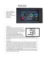
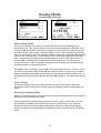
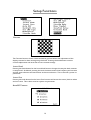
Satlook Micro G2 / HD User Manual ______________________________________ ______________________________________ Contents Overview page 3 Quick Start page 4 EasyFind Mode page 6 Digital Mode page 7 Spectrum Mode page 13 Analog Mode page 15 Setup Functions page 19 Loading New Firmware page 24 Using PC to Transfer Transponder Data page 25 Appendix A - Saved Parameters page 26 Appendix B - Universal LNB Primer page 27 Appendix C - DiSEqC Primer page 28 Appendix D - DVB-S and DVB-S2 Primer page 30 Appendix E – UniCable Primer page 31 Appendix F - Satlook G2 and HD *.smd File Structure page 33 Appendix G - Satlook G2 Specifications page 34 Appendix H - Satlook HD Specifications page 35 Glossary page 36 This manual is applicable for the Satlook G2 with firmware level above smG2HD-106. For earlier firmware revisions, use the Satlook G2 User manual (updated September 20, 2010) 2 Overview The Satlook G2 and Satlook HD are Satellite Test Equipment for the professional made in Sweden. The Satlook G2 can receive DVB-S satellite signals and the Satlook HD can receive both DVB-S and DVB-S2 satellite signals. Both use advanced demodulators and can “lock” on transponders using automatic modulation type, symbol rate and FEC selection. They are easily operated with just three controls and the basic functions are easy to learn. The instruments are provided with a 3" LCD which is used to display information such as signal strength, Spectrum, or Digital information. The Satlook G2 and Satlook HD can be used to measure satellite signals from two LNBs at the same time. Signal strength is presented graphically on the LCD display in form of thermometer scales. They can also sound a tone which increases in pitch with signal level on an internal loudspeaker. They can store 100 positions of Satellite transponder information. The instruments can easily scan through the memory positions and identify the various Satellite transponders. The polarisation of the LNB is switchable by setting the LNB voltage to 13V or 18V and the High Low band with a 22 kHz signal. The DiSEqC function controls all DiSEqC accessories such as LNBs, switches, and positioners. The instruments are supplied with a built-in and rechargeable battery and a carrying case for protection of the instrument in the installation environment. 3 Quick Start Power On/Off Button Menu Knob and Button LNB-A connector LNB-B connector Power Input for charging RS232 Port Reset Button Power On The Satlook G2 / HD is turned on by pressing and holding the power on button for one second. Power on tones indicate that firmware loading has started. This takes about six seconds for the Satlook HD and is shown by a progress bar on the display and a pattern on the blue LEDs. The initial mode can be set by the user for convenience. Pressing and holding the power button also turns off the instrument. The button must be held for more than one second in order to turn the unit off. The Satlook G2 / HD also has an automatic power down that is adjustable which will turn the unit off when there is no activity. This can be set using the Setup Menu. Navigation The Menu Button and Menu Knob are the two controls used for navigation through the menus and selection of functions. When the menu is off, pressing the Menu Button shows the Menu. It is shown at the active mode, so if the Satlook G2 / HD is in Digital mode,the menu is shown with the Digital entry at the top. Using the knob, the function that is to be executed is shown highlighted. Pressing the Menu Button causes the function to be performed. For simple functions such as switching the LNB Voltage with the 13V/18V function, the Satlook G2 / HD performs this function, turns off the menu, and immediately returns to the current mode. For other functions, a new screen with choices is presented. Pressing the Menu Button selects the highlighted item. Some of these other functions have an exit function that is used to return to the current mode. 4 The Menu Knob is used for Frequency adjustment when in the Digital mode or the Spectrum mode. When the Menu Knob is turned slowly, the frequency is changed by 1MHz, but if rotated rapidly, the frequency step is increased allowing for quick movement to the correct frequency. Charging Before using the Satlook G2 / HD, it should be fully charged. To charge the instrument, connect the external power supply or 12V Car Cigarette Lighter Plug and then plug the external power supply into the DC Input connector. The charging process will begin and the blue LED lights will cycle indicating charging. The charging mode and time of charging are displayed on the screen. A full charge can take up to 14 hours, but depending on the battery state can be completed sooner. When charging is complete, the bottom LED will be lit indicating that the charging is complete. The Satlook G2 / HD can be operated using the external power supply, but when the instrument is on, no charging is being performed. The battery state is indicated on the Analog screen by a battery symbol. 5 EasyFind Mode The EasyFind Mode is an easy way to point the dish at installation. When the EasyFind Mode is entered, the Profile defined in the Setup EasyFind Configuration is used. The five satellite transponders (or in the case of All Sats, all of the memory positions) which are in the Profile can be selected with the knob. Initially the display will appear as in the left diagram above and the RF signal will be indicated on the display and by a tone with increasing frequency as the RF signal increases. Turn the knob to select one of the five transponders in the Profile. Point the dish in the approximate position, and move it slowly until the Satellite is found as in the right picture above. There is an audible indication of the correct satellite and a different audible indication if the wrong satellite is found. If the indication is correct, then the screen will show the NIT data after a few seconds for final confirmation. Now the Digital mode can be used for final peaking. EasyFind Mode is exited by pressing the button. 6 Digital Mode Locked Not Locked About Digital Mode When the user enters Digital Mode, the Satlook G2 will attempt to receive a DVB-S signal at the current frequency and the Satlook HD will also try to receive a DVB-S2 signal. The current frequency is displayed in the centre of the screen and can be changed by the knob (within the limits of the current LNB type and the 22 kHz setting). The state of the battery is displayed in the upper right corner of the screen. When a signal is received, the Satlook G2 / HD is “locked” and the modulation mode is displayed. This will be shown as QPSK, or with the Satlook HD, QPSK HD or 8PSK HD. The current FEC and symbol rate are shown along with the LNB type definition being used. If the signal is locked, then the frequency displayed includes the frequency offset to the signal centre frequency. Usually, the instruments will lock to a signal up to 5MHz offset. When not locked, the frequency display contains no offset and an Automatic Search is started in the direction given by the knob. Four boxes are shown in the upper left to indicate the state of locking. For the Satlook G2, from left to right these are: QPSK Lock, Descrambler Lock, Byte Align Lock, Viterbi Lock. For the Satlook HD, from left to right these are: Tuner Mixer Lock, Tuner DAC Lock, FEC Lock, Demod Lock. In Automatic Search, the Satlook G2 / HD checks the signal power at each 3 MHz interval and if the signal is a peak, it will attempt to lock using the current Modulation settings defined in the Setup/Modulations screen (DVB-S, DVB-S2, DVB-S Low Symbol rate). The Satlook G2 searches for QPSK signals. The search will stop when a signal is locked. Turning the knob re-starts the search in the direction of the knob turn. For Universal LNBs, if the frequency reaches 11900 MHz in low band, the 22kHz signal will automatically switch on and the search continues in high band. When searching down, when the frequency reaches 11520 MHz in high band, the 22kHz will automatically switch off and the search continues down. The Search will end when a signal is locked or the frequency limits are reached. Manual Tuning can be entered using the Digital Menu and is active until the next press of the menu knob. With the Satlook HD, in order to lock on signals when the signal symbol rate is less than 15000 MSymbols/sec, the option “Low Symbol Rate” must be selected in the 7 Setup Modulations. On both instruments, for symbol rates below 7000 MSymbols/sec, the signal identification may take several seconds. A constellation pattern is shown which is formed from a small subset of the IQ decision points received by the demodulator. Occasionally, during an attempt to lock, a calibration pattern can be observed momentarily. This is not a real signal, but is an artefact of the demodulator process. The current state of the 22 kHz signal and the LNB voltage are displayed at the left. These are mirrored by the blue LED displays. Once a transponder signal is locked, the Network Information is displayed at the top of the screen. This can take some time to appear once the transponder is locked. The first information that will appear is ONID (Original Network ID) and TSID (Transport Stream ID) data and then the NIT name and Orbital Position will follow. The ONID and TSID are displayed in hexadecimal. The transponder is supposed to send this data at least every 10 seconds, but sometimes there will be a transponder not sending any NIT data. Also you should be aware that sometimes a transponder will send incorrect satellite position data, because they are being used to repeat a transport stream used on another satellite. Visible Thermometer Bars There are four thermometer bars displayed to indicate the state of the signal being received. For all of these, the higher the thermometer bar, the better the signal quality. Each of these thermometer bars has the recent maximum displayed as a single bar. This maximum decays over time and so automatically allows for peaking adjustments. The four thermometer bars are SIG, SNR, BER and MER. SIG This is the power level of the signal at the current frequency. It is always displayed whether the signal is locked or unlocked. This is not the same as the display on the Analog screen. SNR This is the signal to noise ratio of the locked signal. This is a measure of the meaningful power in the signal to the background noise of the signal. It is shown in dB and is calculated by the demodulator using SNR = 10log10(Psignal/Pnoise) BER This is the bit error ratio of the signal. The lower this value is, the better the signal. It is shown in reverse on the thermometer bar for convenience so that a maximum can be easily found. For DVB-S QPSK signals, this is BER = ErrorpreViterbi/(BitRate TimeLock). For DVB-S2 QPSK or 8PSK signals, the BER is estimated from the ratio of Un-correctable blocks to Correctable blocks. MER This is the modulation error ratio in dB. It is calculated from the constellation pattern and represents how close the I and Q decision points are to the ideal position. A typical MER value is 16 dB. A higher value is better and represents a closer spread of IQ decision points. A sample of 200 points is used for the calculation. 2 2 ∑ I ideal + Qideal MER = 10 log10 ∑ I 2 + Q2 error error 8 ( ( ) ) Accessing the Digital Menu When in the Digital Mode, turning the knob will change the current frequency. The Menu button will activate the Digital Menu. Frequency / Search This function enters Digital Mode with the Search function disabled. Tuning can be performed manually using the knob. The manual tuning mode will remain active until the Search function is executed. Load Memory The Load Memory function is used to load the settings for frequency, polarisation, and band from the permanent memory. The knob is used to select the desired memory and the knob button loads this memory. Once a memory location has been loaded, Load Mode is active. In Load Mode, turning the knob, turning the knob selects the next memory location, loads the memory and displays the memory number and name. To exit the load mode, the user presses the button once again and then the knob determines frequency on the Digital screen as before. When a frequency is locked in Digital Load Mode, and NIT data is available, it replaces the memory position and name display, but if the knob is turned, then a new memory position is loaded and the memory position number and name displayed. This is replaced by NIT data when it is available. 9 Channels This shows the services available on the current transponder. The type of service is shown in the first column. RA is a radio service, TV is a standard definition service and HD is a High Definition service. Other service types are listed by number. The Service ID number, Service Name and Service Provider are shown. The services shown will update as more services are found. The knob can be used to scroll up and down to see all of the services. 13V/18V The LNB voltage can be switched from the Digital Menu. 22kHz The 22kHz signal can be switched from the Digital Menu. DiSEqC Command This is the same as the function available on the Analog menu. Constellation Constellation This function shows a larger version of the constellation presentation for a more detailed view. The current frequency is displayed at the top and rotating the knob will allow this to be changed. If locked, the current modulation is displayed along with the BER, SNR, and MER thermometer bars. The current Bit Rate of the transponder is shown with the Satlook HD. This information is not available on the Satlook G2. The 8PSK display shows the target boxes outlined. These target boxes are moved to the average target position. 10 X Polarity This function can provide a visual reference of the signal level of the vertical and horizontal polarisations at a frequency. This can be used to adjust the LNB skew for maximum isolation. Many satellite transponders (like Astra 28.2 for most frequencies) operate so that the vertical and horizontal polarisation signals are not usually at the same frequency, but others (like Hotbird) have some transponders that operate with vertical and horizontal polarisations at the same frequency. To ensure that you use a “good” transponder for this isolation test, use the Spectrum Analyzer to check the signals. SNR Beeper This function starts the beeper with a frequency depending on the current SNR reading. As the SNR increases, so does the frequency of the tone. Transponder Check This function allows checking of all transponders for some satellites. The satellites that are testable with this function are Astra 28.2E, Astra 23.5E, Astra 19E, Hotbird 13E, Sirius 4.8E, and Thor 0.8W. When the function is started, the satellite to be tested is shown on the screen. Turning the knob selects a different satellite to be tested. Pressing the button starts the test. Each transponder on the satellite is checked and if locked, then an upward vertical line is shown. With the Satlook HD, if the transponder is DVB-S2, then the vertical line is shown slightly longer. On the Satlook G2, this transponder will fail to lock. If the transponder cannot be locked after three tries, then the vertical line is downward. At the completion of the test, the knob can be used to review any missing transponders and show the frequency and polarity for further checking using the Spectrum or Digital modes. Although all transponders for a satellite are tested, failure to lock may occur for several reasons. This is an accelerated test designed to run quickly and it is possible that the demodulator may not lock in the short time allowed, or the transponder may not have a broadcast “footprint” that covers your area. 11 Save Memory The Save Memory function saves the current Frequency, Polarity (13V/18V), Band (22kHz signal state), and LNB Type in the selected location. The knob can be turned to select the desired memory position to change. If a new name is needed for the memory position, then it can be entered on the next screen when the menu button is pressed to select the memory position number. If the memory location name is already correct, then press the menu button again to save the frequency data in this memory position. If the name needs to be changed, use the knob to make the changes. Characters can be added by selecting the character with the knob and then pressing the menu button. Characters can be deleted by selecting the “Delete” function with the knob and then pressing the menu button. “Clear” will erase the name, and “Cancel” will abort saving the memory position. 12 Spectrum Mode G2 Spectrum HD Spectrum About Spectrum Mode The Spectrum Mode shows the signal power versus frequency around the current frequency. On entry to the Spectrum Mode, the spectrum cursor is in the centre of the display and the centre frequency is set to the last used frequency. Turning the knob changes the cursor frequency, and the flag shows the current cursor frequency and for a Universal LNB also shows the Polarity. If the cursor frequency is adjusted to a position that would be offscreen, the screen is cleared and the spectrum plotted with the cursor at the new frequency in the centre. The current frequency is used for other modes, so the Spectrum Mode can be used to find a signal of interest, and then the Digital Mode can be used for more complete examination. The user can exit Spectrum Mode by pressing the button. Accessing the Spectrum Menu The Menu is activated by pressing the button. At this time, the Spectrum options can be changed or other functions in the menu can be used. 13 Sweep The Spectrum Sweep can be changed from 1 MHz per increment to 10 MHz per increment. The user setting for the Spectrum Sweep increment is then saved and restored on power up. 13V/18V and 22kHz 22kHz From the Spectrum Menu, the Polarity and Band can be changed with the 13/18V and the 22kHz signal. 14 Analog Mode About Analog Mode The screen in Analog mode shows the relative RF level for the two LNB inputs on a thermometer bar. This is the RF level for the IF band from 920 MHz to 2150 MHz. For a Universal LNB, the Satellite band will be selected from one of the four quadrants by the 13V/18V and the 22 kHz signal. The LNB voltage of 13V or 18V is displayed by the blue LEDs and also on the screen. The LNB signal 22kHz is displayed by the blue LEDs and also on the screen. The Attenuator state is shown on the screen and is displayed by the blue LEDs. An alternate presentation of the Analog Mode is shown on the right picture. If only one LNB is needed, then the Analog NIT mode can be used. This searches the current IF band for a valid transponder and when found, displays the Original Network ID, Network Name, and Orbital Position. The LNB Current is displayed. Typical LNB current will range from 90 to 175 mA. If there is a short in the satellite cable to the LNB, the screen will show an overcurrent condition. When both LNB-A and LNB-B are connected, you will see the combined LNB Current. If the LNB Current exceeds about 450mA, then the LNB Voltage of 13V/18V will be turned off. Power Display The battery charge level is shown approximately by the battery symbol. When the Satlook G2 / HD is connected to a power supply, the battery symbol is replaced by “Ext Power”. Accessing the Analog Menu When in the Analog Mode, turning the knob or pressing the knob button will activate the Analog menu for the Analog functions. Rotating the knob will scroll through the menu items. To select a menu item, press the menu button. If the Menu Timeout function (set using Setup mode) is set, then the display will revert to the Analog Mode display after a timeout, otherwise the Analog menu will continue to be displayed until an Analog function is selected from the Analog menu. 15 Analog Menu Functions 13V/18V 13V/18V This function toggles the LNB voltage. If the voltage is 13V, it is changed to 18V and vice versa. The LNB voltage is used to select the Polarity for a Universal LNB. 13V selects Vertical Polarity and 18V selects Horizontal Polarity. The user setting for the LNB voltage is saved and restored on power up. 22kHz This function toggles the LNB 22kHz signal. If the signal is off, it is turned on and vice versa. The 22 kHz signal selects the band for a Universal LNB. If the 22 kHz signal is off, then a Universal LNB selects the low band (10670 MHz to 11900 MHz). If the 22 kHz signal is on, the high band is selected (11520MHz to 12750MHz). The overlap region from 11520MHz to 11900MHz can be received with the 22 kHz signal either on or off. The user setting for the 22 kHz signal is saved and restored on power up. Beeper This function toggles the RF signal beeper to one of three modes. The frequency of the beeper increases with RF signal strength. - if off, it is set to use the RF signal from LNB-A - if currently LNB-A, then it is set to use the RF signal from LNB-B - if LNB-B, it is set to off Attenuate This function toggles the RF attenuator on or off. This inserts about 3dB into the RF path. It attenuates both LNB-A and LNB-B. There is no effect on signals in Digital Mode. MaxHold This toggles the MaxHold function from off to on and vice versa. When the MaxHold function is on, the maximum RF signal value for LNB-A and LNB-B is displayed as a line on the thermometer bar. BackLight This toggles the BackLight on or off. Analog NIT This toggles the Analog NIT function on or off. When on, only LNB-A is shown and the current IF band is searched for a valid transponder. If a valid transponder is found, then the Original Network ID, Network Name, and Orbital Position is displayed. When off, the display shows both LNBs and no network identification is performed. 16 DiSEqC Cmd This function sends a DiSEqC command. Turning the knob shows the DiSEqC command selected and pressing the knob button sends this command. The thermometer bar shows the RF Level for LNB A. This is RF level for the IF band from 920 MHz to 2150 MHz. The Exit position returns the user to Analog mode. The DiSEqC commands that are sent are detailed in appendix C (DiSEqC Primer). Positioner This function sends a DiSEqC command to a positioner. Turning the knob shows the DiSEqC command selected. Pressing the knob button will then send this command. The thermometer bar shows the RF Level for LNB A. This is RF level for the IF band from 920 MHz to 2150 MHz. The Exit position returns to the Analog Mode. The DiSEqC commands that are sent are detailed in Appendix C (DiSEqC Primer). Go East: East This sends the DiSEqC command to move the positioner to the East. As long as the button is pressed, the movement continues. When the button is released, a DiSEqC Halt command stops the motion. Go Home: Home This sends the command to “Home” the positioner. (This command is Goto Pos 0) This is normally due South, but for some positioners may be the extreme easterly limit. Go West: West The DiSEqC command to move the positioner to the West. As long as the button is pressed, the movement continues. When the button is released, a DiSEqC Halt command stops the motion. SetEast: SetEast Set the East “soft” limit for the positioner at the current position. Clr Lim: Lim Clear the “soft” limits. 17 SetWest: SetWest Set the West “soft” limit for the positioner at the current position. Goto Pos: Pos This sends the DiSEqC command to the positioner to move to a stored position from 1 to 31. The knob selects the position number to move to and pressing the knob button sends the command. Save Pos: Pos This sends the DiSEqC command to the positioner to save the current position as a “stored” position from 1 to 31. The knob selects the position number that this will be called and pressing the knob button sends the command. Goto X: X This sends the DiSEqC command to move to a position calculated for the Satellite Angle desired. The knob selects the Satellite Angle that will be used and pressing the knob button sends the command. To move the positioner to HotBird for example, the command to send would be Goto X 13.0 E. The Goto X function calculates the amount to move the positioner from the Satellite Angle and the user Latitude and Longitude. In order for the command sent to be correct, the Latitude and Longitude must be set for the user location. MyLat: MyLat This function is for the entry of the Latitude of the user location. Turning the knob will show the selected latitude from 90.0o South to 90.0o North and pressing the knob button will save this setting. This setting will be restored on power on. MyLong: MyLong This function is for the entry of the Longitude of the user location. Turning the knob will show the selected Longitude from 180.0o East to 180.0o West and pressing the knob button will save this setting. This setting will be restored on power on. 18 Setup Functions Contrast The Contrast function shows a black and white grid and allows the adjustment of the display contrast for best viewing using the knob. Pressing the knob button exits the contrast adjustment and saves the current contrast settings. Invert Knob Pressing the Knob button for the Invert Knob function changes the way the knob rotation is interpreted. At default, rotating the knob clockwise means that frequency will increase and the menu selection will move down to the next selection. This is saved as a power on parameter. Invert Scrn Pressing the knob button for the Invert Scrn function will invert the screen, black to white and vice versa. This is then saved as a power on parameter. AutoOff Timeout 19 This function sets the AutoOff timeout if required. If the knob button or knob is not used for the timeout period, then the Satlook will display “AutoOff” and power down. This setting is then saved as a power on parameter. Backlight Configuration The backlight can be set so that it will turn off after a delay. The setting is then saved as a power on parameter. Set LNB Type The LNB used can be set so that the frequency displayed is correct and the stored transponders are correctly used. The “Universal” entry sets the LNB so that two local oscillator frequencies (9750MHz and 10600MHz).are used for conversion. These are switched using the 22kHz signal to select the 9750MHz local oscillator when the 22kHz is off and the 10600MHz local oscillator when the 22kHz is on. The LNB downconverts the satellite signal to the Intermediate Frequency as: IF = FrequencySatellite - FrequencyLO The “10.7 Univ” entry is similar except that the two local oscillator frequencies are 9750MHz and 10700MHz. The “5.15” LNB type is for C Band. The LNB downconversion for this LNB is: IF = FrequencyLO - FrequencySatellite The “IF” entry uses no conversion. The frequency displayed is in the 950MHz to 2150MHz band. UniCable LNB selection uses the tuning commands for UniCable. The User Band default is 1 and can be changed using the Setup -> UniCable Band command (see page 22). This 20 command is also used to test the four User Bands. The User Bands are assumed to be 100 MHz wide. (Using the Spectrum mode will show how wide the User Band is and whether it is symmetrically about the tuning frequency.) In the Digital mode, retuning is performed every time the frequency is changed using the knob or the Band/Polarisation is changed. In the Spectrum mode, no retuning is performed while the cursor is within the UniCable Band of 100MHz. To force the retuning, exit the Spectrum mode and reenter. Entry to the Digital Mode and Spectrum mode force UniCable re-tuning. During UniCable LNB use, the 13V/18V and the 22kHz signal indications are still used for Polarisation and Band selection, but they are not actually imposed on the LNB cable. Modulation This function is only available with the Satlook HD. It sets the modulation type that will be tried when in the Digital Mode. This can be used with the search function to find only transponders that are DVB-S or DVB-S2. The BlindTune algorithms used will search for Symbol Rates from 15000 to 30000. In addition, the Low Symbol rate option can be enabled to allow the search for Symbol Rates from 1000 to 15000. This will search for QPSK only in this region. This option adds extra time to the BlindTune algorithm so that when these low symbol rates are not needed, it should be turned off. This setting is a power up parameter. StartUp Mode The mode on power up can be chosen for the Satlook G2 / HD. This setting is a saved parameter. 21 Menu Timeout The menu timeout can be set so that if no action is performed, then the display of the current mode will resume automatically. If “No Time Out” is chosen, the menu will remain active until the button is used to select a function. EasyFind Setup The EasyFind Setup function allows the EasyFind to be configured for the user situation. The “Profile” can be selected with the knob button and one of five profiles stored in memory can be selected. An additional Profile “All Sats” allows the use of any memory position in EasyFind Mode. When the Profile is defined, the five Satellites in the profile can be selected from the memory positions. UniCable Band The UniCable User Band used for tuning can be selected to be other than the default of User Band 1. At the start of this function, the four User Bands are verified. After this test, any of the four bands can be selected as the User Band to be used for tuning for detailed testing of the UniCable LNB. The User Band can be selected regardless of the test results, so the User Band could be set with the LNB disconnected. The power up default of the User Band is 1. If the User Band is already in use by another receiver, then the test will fail for this User Band. 22 Language The menu language can be set to other languages than English. Supported are Swedish, French, German, Polish, Dutch, Spanish, Italian and Turkish. Version Satlook HD Satlook G2 The Version menu shows the software and hardware versions and related information. 23 Loading New Firmware A new firmware version can be loaded to correct issues that are reported in the firmware release notes. The firmware for the Satlook HD is identified as “smHD60-EU.hex” with the number “60” being the version number. Newer firmware designed to be common with the Satlook G2 is identified as smG2HD106-EU.hex This firmware can be used on either the G2 or the HD. Do not load any firmware without these types of name, it will be for a different instrument and will not work on the Satlook G2 or HD. Use the Version screen in the Setup Menu to determine the current software version. In order to load firmware, you must have a PC which supports an RS232 connection. The firmware loading must be performed with the external charger connected. The RS232 cable to be used is supplied as part of the kit with the Satlook G2 / HD. Some laptops do not have an RS232 connection, but a USB to RS232 adapter can be purchased at low cost. Connect the Rs232 cable from the computer to the instrument. Run the firmware download file “FDL.exe”. Select the RS232 port on the computer. Normally, the port is COM1 but some USB to RS232 will use some other port. If desirable, this USB to RS232 conversion device can be made to always use COM1 by clicking Control Panel / Device Manager / Ports and in the Advanced settings for the adapter set to COM1. Select “Send Firmware” and the display with be “Searching”. Connect the Satlook G2 / HD to the external charger and the display will change to “Found”. To verify this, check the Blue LEDs to see if they are not changing. If they are in cycling pattern displaying the “charging pattern” then the process must be restarted. An alternative method of starting the firmware loading process is to have the Satlook G2 / HD connected to the external charger and charging when starting the firmware load. When the “Searching” message is displayed, momentarily press the Power On button for less than a second. It is only during power up under external charge that the unit will check for an RS232 connection for firmware loading. Now choose the firmware file. Normally, the firmware will be in the same direction as “FDL.exe” but if not, you can navigate to the correct directory and select the firmware file. Once the file is selected, the firmware loading will take about 10 minutes and then the Firmware Downloader program will display “Download Complete” and the Satlook G2 / HD will revert to the “charging pattern” shown by the blue LEDs in a cycling pattern. 24