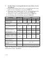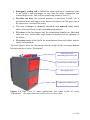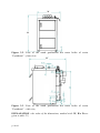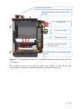
1
User manual
Green ECO Therm
for installation and exploitation
of wood gasification hot water boiler of series :
PYROTHERM
http:// www.greenecotherm.eu
Producer
Address
Phone
Fax
e-mail
home page
ZMM Haskovo Plc.
Bulgaria, Haskovo 6300, “Saedinenie” 67 blvd.
+359 800 15 145
+359 38 603070
[email protected]
www.greenecotherm.eu
Thank You for buying the wood gasification boiler of series “Pyrotherm”.
This manual will help You to use and maintain the unit properly.
The user manual applies to the following types of hot water boilers:
“Pyrotherm 25”, “Pyrotherm 32”, “Pyrotherm 42” and “Pyrotherm 52”.
This document is intended to be used as additional information for the
service team, which will install and adjust the boiler, as well as maintenance
information, which will help the end user.
The producer requires the service staff, which will perform the above
mentioned procedures, to get training course at the producer’s training center
and get certified as well.
ATTENTION! In interest of your personal security it is
obligatory to read thoroughly and carefully this instruction
manual before proceeding with any actions with the system –
mounting, connecting, etc. its elements. In case that
requirements, depicted in this manual are not satisfied,
failures of any element of the system could be expected, or
even fatal consequences, for which the boiler’s producer does
not take responsibility;
User manual for installation and exploitation of wood gasification hot water boiler of
series „Pyrotherm”
(Document version: 16.11.2011 13:32:00)
p. 2/69
CONTENTS
p.
1.
Main properties and advantages of the wood gasification hot water
boiler of series “Pyrotherm” .............................................................................. 5
1.1.
Basic information for the hot water boiler.................................................. 5
1.2.
Basic information for the pyrolisis process................................................ 5
2.
Technical data of wood gasification hot water boiler of series серията
“Pyrotherm” ........................................................................................................ 8
3.
Description of the wood gasification hot water boiler of series
“Pyrotherm”. ..................................................................................................... 12
4.
Installation of the hot water boiler of series “Pyrotherm” ................. 18
4.1. Basic requirements for installation of wood gasification hot water
boiler of series “Pyrotherm”:........................................................................ 18
4.2. Basic requirements for installation of wood gasification hot water
boiler of series “Pyrotherm”, considering it’s easy maintenance and
servicing: ......................................................................................................... 19
5.1.
Basic fuel requirements....................................................................... 26
5.2. Basic requirements for exploitation of the hot water boiler,
connected to a heating system....................................................................... 26
5.3. Starting wood gasification hot water boiler of series “Pyrotherm”
procedure. ....................................................................................................... 28
5.3.1.
Interface control board of wood gasification hot water boiler
of series “Pyrotherm” ....................................................................................... 30
5.3.2.
Start-up initialization of the boiler .......................................... 32
5.3.3.
Ignition of the fuel and boiler’s heating up ............................ 33
5.3.4.
Adjustment of the air flow rate control thermovalve ............ 36
5.3.5.
Nominal operating mode of the boiler..................................... 37
5.3.6.
Fuel hopper charging................................................................ 39
5.3.7.
Adjustment of the operating parameters of the boiler. ......... 41
5.3.8.
Estimating the thermal capacity of the boiler ........................ 47
5.3.8.1.
Decreasing the thermal capacity of the boiler ........................ 48
5.3.8.2.
Increasing the thermal capacity of the boiler......................... 48
p. 3/69
5.4.
Operation of the boiler in “stand-by” mode ..................................... 49
5.5.
Stopping the operation of the boiler. ................................................. 50
5.6.
Turning OFF the boiler....................................................................... 51
•
5.7.
Emergency boiler stop. ......................................................................... 51
Cleaning the ash of the boiler ............................................................. 52
5.8. Showing and teaching the end user about the maintenance and
adjustment procedures of the boiler ............................................................ 59
5.9.
Safety and unexpected risks ............................................................... 60
5.10. Operation faults and their repairing ................................................. 61
5.11.Hot water boiler warranty form completion. ..................................... 64
5.12. Actions, after the unit is not in exploitation anymore...................... 64
6.
Electrical scheme of control board of wood gasification hot water
boiler of series “Pyrotherm”. ........................................................................... 65
QUALITY CERTIFICATE ............................................................................. 66
WARRANTY CONDITIONS .......................................................................... 67
WARRANTY SERVICE PROCEDURES LIST ........................................... 69
p. 4/69
1. Main properties and advantages of the wood gasification hot
water boiler of series “Pyrotherm”
1.1. Basic information for the hot water boiler
The wood gasification hot water boiler of series “Pyrotherm” is steel-plate
hot water boiler, which uses solid biomass fuel in shape of wood logs. The
boiler is designed to be connected to local hot-water heating systems, as well
as heating up domestic hot water. The boiler uses wood logs with moisture
content up to 20% (the parameters of the fuel are described below), the
resulting heat energy from thermo-chemical conversion (i.e. combustion
process) is transmitted to the circulation water in its water jacket and the heat
energy is transported to the heating system/consumer. The design of the
boiler is optimized in order to achieve high efficiency and low cost heating
process, as well as easy maintenance, ash removal and servicing. The hot
water boiler of series “Pyrotherm” is manually fuel fed boiler. The
combustion process is organized in the combustion chamber of the boiler.
The set of the hot water wood gasification boiler of series
“Pyrotherm” consists of the following :
• Hot water boiler of series “Pyrotherm” - 1 sp;
• Combustion chamber ceramic directing element - 1 sp;
• Thermovalve for control of air flow rate – 1 sp;
• Steel ash cleaning brush – 1 sp;
• Ash scrapper – 1 sp;
• User manual for installation and exploitation of hot water boiler of
series “Pyrotherm” – 1 sp;
1.2. Basic information for the pyrolisis process.
The pyrolisis process is chemical decomposition of the biomass through
heating of the matter. The word pyrolisis is coined of two Greek words
„pyro” – fire and „lysis” – decomposition. The wood pyrolisis process is
realized at certain conditions, the products of this process are volatile gases,
which are utilized like gas combustion process. The pyrolisis gases are
extracted out of the fuel chamber and are directed through a ceramic nozzle
and oxidized in the combustion chamber, reaching high intensity of the
combustion process and high efficiency. This process have many advantages
– the combustion process could be optimized and allows efficient utilization
of the fuel material. The design of the how water boiler of series “Pyrotherm”
allows optimal conditions for the above mentioned process, so they are
p. 5/69
named “pyrolisis” hot water boilers. The fuel ignition, as well as the fuel
charging is done manually, the ash deposition cleaning is also done
periodically by hand – this allows achieving optimal combustion process and
efficient and low cost heat energy for the heating system.
The boiler could utilized the following fuel – wood logs, preferably
chopped wood logs, having the following properties:
o Pure wood, contaminated (i.e. painted, chemically treated as well as
other mineral or organic substances) wood is not allowed;
o The length of the wood logs should correspond with the depth of the
fuel chamber of the boiler – see the specification of boiler;
o The cross section (the diameter) of the wood logs should be : D ≤
200mm;
o The moisture content of the raw material should be less than 20%
(Wr ≤ 20%);
o It is possible along with the wood logs to utilize other wood based
fuel – like saw dust, shavings and other small fuel particles, but their
quantity should be less than 20% of the total charged fuel in the
chamber of the boiler;
The boiler consists of
• Steel plate heat exchanger, which transfers the heat energy from the
flue gases to the heating media (in most cases this is circulating water);
• Flue gas fan, which extracts the exhausted gases out of the boiler;
• Fuel chamber;
• Ignition flap, utilized at the initial phase of fuel ignition and boiler
heating up;
• Ceramic insulated combustion chamber;
• Convective duct, which also heats up the air, consumed for the
combustion process;
• Dash board for control and monitoring of the operating parameters of
the boiler;
• Thermal insulation – made of mineral wool;
The boiler is equipped with
• Thermo-manometer, which indicates both the operating temperature
and the operating overpressure of the circulating water;
• Operating thermostat, which controls the flue gas fan;
p. 6/69
• Thermostat, which indicates the thermal condition of the boiler and
indicates if the boiler needs to be cleaned of the accumulated ash option;
• Alarm thermostat, which switches off the power supply of the boiler in
alarm overheating mode of the boiler;
• Emergency cooling coil, utilized in case of alarm overheating of the
boiler;
Advantages of the boiler
• The boiler is designed to utilize wood biomass, which makes it
ecologically clean and environmentally friendly and its operation does not
contribute to the global warming of the Earth;
• The price of the thermal energy, derived by utilizing the boiler like local
energy source is less influenced by the world prices of the other fuels and
energy sources, which makes it attractive and competitive, compared with
the common known energy sources;
• The manual feeding of the fuel in the boiler allows easy control of its
thermal capacity, which guaranties high thermal comfort and fuel savings;
• High efficiency;
• Low pollutants;
• Opportunity to heat up domestic hot water (DHW);
• Simplified maintenance and service;
• Minimal running costs;
p. 7/69
2.
•
•
•
•
Technical data of wood gasification hot water boiler of series
“Pyrotherm”
Thermal and technical data for the wood gasification hot water
boiler of series “Pyrotherm” are given in Table 2.1;
Dimensions and technical data for the wood gasification hot
water boiler of series “Pyrotherm” are given in Table 2.2;
Parameters of the recommended fuel are given in Table 2.3;
Low heating value of wood logs is given in Table 2.4;
Parameter
Model
Nominal thermal capacity
Thermal capacity
operation range
Utilized fuel
Wood logs consumption
rate at nominal thermal
capacity
Fresh air flow rate,
required for effective
combustion process and
boiler operation
Flue gases mass flow rate
Averaged
wood
logs
consumption rate (the boiler
is operating in a popular heating
system)
Thermal efficiency at
nominal capacity
Flue gasses temperature
at nominal thermal
capacity
Solid fuel residue
Dimension
Value
kW
25
25
32
32
42
42
52
52
kW
13 - 25
16 - 32
21 – 42
26 - 52
Wood logs for heating purposes, water content up to
20%
kg/h
7.9
10.2
13.3
16.5
kg/h
93
120
157
195
m3/h
81
104
136
169
g/s
28.1
36.1
47.3
58.6
kg/h
5.5
7.0
9.3
11.5
℅
85
ºC
180 – 250
ash
The quantity depends on the ash contents in
the raw fuel, as well as operating conditions
Table 2.1. Thermal and technical data for the wood gasification hot
water boiler of series “Pyrotherm”;
p. 8/69
Parameter
Model
Weight
water jacket capacity
Fuel chamber capacity
Interval of time for nominal
thermal capacity after fuel
chamber charging
Maximal wood log length
Overall
W - width
dimension of the D - depth
system: (WxDxH) H - height
Operating overpressure of the
circulating water
Hydraulic losses of the
circulating water at nominal
thermal capacity
Heating system expansion
vessel type
Factory tested overpressure
Recommended circulating
water temperature in the boiler
Minimal recommended return
water temperature in the boiler
Draught
Supply/return
flow
Drainage
Connections
Emergency
cooling coil
Flue gases duct
Power supply
Power supply cable
Electrical capacity
Electric protection
Class of the boiler
(according to EN 303-5)
Dimension
330
60
100
16 - 20
Value
25
330
59
100
16 - 20
32
330
59
100
16 - 20
hours
mm
42
370
78
130
20 - 24
52
450
89
170
25 - 30
2-3
330
330
500
700
1123
1321
14.23
8.37
780
mm
975
975
1282
MPa
hPa
0.2
3.54
5.27
-
opened or closed
MPa
0.4
ºC
80 - 85
ºC
60
hPa
0.18 - 0.24
G
1½”
2”
G
3/4”
G
½”
mm
VA
-
150
L1, N, PE, 50Hz; 230V;
3 x 1.5mm2
32
32
65
IP20
3
Table 2.2. Dimensions and technical data for the wood gasification
hot water boiler of series “Pyrotherm”;
p. 9/69
65
Parameter
Fuel type
Length of the wood logs
Moisture content
Low calorific value of the fuel (LHV)
Dimension
Value
Wood logs
mm
See Table 2.2.
≤ 20%
%
MJ/kg
>13.9
kWh/kg
>3.9
Table 2.3. Proximate parameters of the recommended fuel – predried
and chopped wood logs;
EXPLANATION: one of the most important parameters of the fuel is its
calorific value (its heat content). The calorific value (also known as heating
value) is function of the moisture content of the wood logs (the moisture is
mechanically conserved water in the fuel. The biomass is a natural product and
the moisture content of a raw material could be 40 to 60% (the just cut down
material can contain up to 80%).
In order to achieve economic operation of the boiler and to achieve
efficient combustion process, it is necessary to supply fuel with minimal water
content, for pyrolisis types of boilers it is recommended the moisture content to
be up to 20%, which is practically realized by natural drying of the material (at
ambient conditions) for a relatively long period of time (at least for a year),
during the summer period the drying is high intensified. The fuel should be
protected from accident moistening (from example by rain or snow). In order to
achieve uniform and intensive during it is highly recommended to chop the wood
logs into smaller pieces. However, it the wood logs are stored for a longer
period (more than two years), its calorific value is also decreased due to
devolatilization of the biomass;
The so called Low Calorific Value of the fuel (LHV) – the heat energy,
achieved at combustion, but the latent heat of the water vapor in the flue gases
is not retrieved could be calculated from the following equation:
LHV =
(
)
HHV * 100 − W r − 2.44W r
, [MJ/kg], where :
100
LHV – Low Heating Value of the fuel, [MJ/kg];
HHV = 18.0 [MJ/kg] – High Heating Value of the fuel (this is the energy of the
fuel, which includes the latent heat of evaporation of the water vapor in the flue
gases, i.e. the water has been condensed);
The dependency of the Low Heating Value as function of the moisture
content Wr is given on the following figure:
p. 10/69
20.000
Low heating
value , [MJ/kg]
18.000
16.000
14.000
12.000
10.000
Low heating
value, [kWh/kg]
8.000
6.000
4.000
2.000
0.000
0
5 10 15 20 25 30 35 40 45 50 55 60 65 70 75 80 85
Figure 2.1. Low heating value of wood log (abscise – moisture content Wr, [%],
ordinate – low heating value LHV);
Moisture content
Wr
[%]
0
5
10
15
20
25
30
35
40
45
50
55
60
65
70
75
80
85
Low heating value
LHV
[MJ/kg]
[kWh/kg]
18.000
16.978
15.956
14.934
13.912
12.890
11.868
10.846
9.824
8.802
7.780
6.758
5.736
4.714
3.692
2.670
1.648
0.626
5.000
4.716
4.432
4.148
3.864
3.581
3.297
3.013
2.729
2.445
2.161
1.877
1.593
1.309
1.026
0.742
0.458
0.174
Table 2.4. Low Heating Value of wood logs as function of moisture content Wr
of the raw fuel % (w.b.);
p. 11/69
3. Description of the wood gasification hot water boiler
of series “Pyrotherm”.
The heat exchanger of the hot water boiler of series “Pyrotherm” complies
with the acting requirements for such kind of units, defined in operating norm :
EN 303-5/2000 – „Heating boilers for solid fuels, hand and automatically fired,
nominal heat output up to 300 kW. Terminology, requirements, testing and
marking”.
The hot water boiler consists of the following elements/modules:
• Heat exchanger is steel plate welded construction. In the upper section of
the boiler is the fuel hopper, which is manually fed with wood logs. This
fuel chamber makes optimal conditions for fuel pyrolisis process and the
volatile gases are directed to the lower section of the boiler, where they
are oxidized in the combustion chamber. In the combustion chamber is
positioned ceramic lining – a nozzle and a flue gas directing element,
which allow efficient combustion process;
• Combustion nozzle, produced from ceramic material, placed in the lower
section of the fuel hopper, which ensures optimal conditions for efficient
combustion process;
• Ceramic directing element, which is positioned in the combustion
chamber of the boiler, allowing high temperature levels and ensures
optimal fuel oxidation;
• Flue gases fan is installed in the back side of the boiler – it transports the
exhausted flue gases out of the boiler and controls the operation of the
boiler;
• Air distribution box, which has primary air control valve. This box also
serves as heat exchanger and preheats the ambient air before being
consumed in the combustion chamber of the boiler. The inlet of this box
has inflow control flap, which is driven by thermovalve and controls the
total mass flow rate of the air, sucked in the boiler;
• Inflow orifice has internal thread (for the size see table 2.2) and is
positioned on the back left lower side of the heat exchanger, the outflow
orifice has internal thread as well (for the size see table 2.2) and is
positioned in the back left upper side of the boiler. Use this orifices in
order to connect the boiler to the heating system;
• Drainage orifice has internal thread (for the size see table 2.2), which
should be connected to a drainage valve;
p. 12/69
• Emergency cooling coil is utilized for alarm cooling of circulating water
in the boiler’s heat exchanger in case that the water temperature has
reached high levels. This coil has connecting thread of size G½”;
• The flue exit duct (the external diameter is described in table 2.2) is
positioned in the back upper of the boiler and extracts the flue gases out of
the convective section of the boiler;
• The heat exchanger is thermally insulated with mineral wool, which
allows lower heat loses to the surrounding atmosphere;
• The doors of the fuel hopper and the combustion chamber are fabricated
from cast iron, which allow high thermal resistance and air tightness of
the boiler;
• The outer covers of the boiler are manufactured from steel plates and are
finally color painted;
The next figures show the dimensions and the design of the wood gasification
hot water boiler of series “Pyrotherm”.
Thermovalve for
controlling the air flow rate
Control board of the boiler
Fuel hopper door
Combustion chamber door
Figure 3.1 Side view of wood gasification hot water boiler of series
“Pyrotherm” – the main elements of the boiler are described;
p. 13/69
W
H
Figure 3.2. View of the wood gasification hot water boiler of series
“Pyrotherm” – front view;
D
Figure 3.3. View of the wood gasification hot water boiler of series
“Pyrotherm” – side view;
EXPLANATION : the value of the dimensions, marked with :W, H и D are
given in table 2.2;
p. 14/69
W
Figure 3.4. View of the wood gasification hot water boiler of series
“Pyrotherm” – back side view;
D
W
Figure 3.5. View of the wood gasification hot water boiler of series
“Pyrotherm” – top view;
p. 15/69
Orifice for extracting the gasses
of the fuel chamber at ignition
Primary air inlet orifice
Fuel hopper
Combustion nozzle
Combustion chamber
Flue gas directing profiled
ceramic in the combustion
chamber
Flue gasses outlet (directed to the
convective duct of the boiler);
Figure 3.6 Cross section view of wood gasification how water boiler of series
“Pyrotherm”;
p. 16/69
Control box of the boiler
Upper lid of the convective duct of the
boiler
Flue gas fan
Flue gas exit duct
Combustion nozzle
Flue gases directing ceramic
profiled element
Lower lid of the convective duct of the
boiler
Figure 3.7. Longitudinal section of wood gasification hot water boiler of series
“Pyrotherm”;
The producer reserves the right to make any changes of the design and
construction of the boiler without obligation to inform the end user.
p. 17/69
4. Installation of the hot water boiler of series
“Pyrotherm”
Norms and requirements.
4.1. Basic requirements for installation of wood gasification hot water
boiler of series “Pyrotherm”:
• The room, dedicated to mount the hot water boiler should be supplied
with fresh air supply duct, necessary for optimal combustion process as
well as room ventilation;
• Installation of the hot water boiler in inhabitable premises, including
dwelling corridors, is not allowed;
• The hot water boiler should be connected to the heating system by
authorized personal only;
• Installation and service procedures of the hot water boiler should be
performed by authorized qualified and certified personal ONLY;
• The wood gasification boiler of series “Pyrotherm” could be attached to a
heating system, equipped with opened or closed expansion vessel, which
should be designed for the water capacity of the entire heating system (its
capacity is calcutated at the step of heating system project development);
• Both the entire heating system and the hot water boiler should be totally
filled with circulating fluid (water) and air-free before operating the
boiler;
• Maintenance procedures of the boiler (as well as the heating system)
should be performed by trained adult persons, which have read the user
manual of the unit;
ATTENTION: at the transport of the boiler, take care to preserve the ceramic
element, mounted in the combustion chamber of the boiler not to be cracked or
damaged (secure the detail, or even transport it separately from the boiler);
Installation procedure of the hot water boiler requires engineering project
for the heating system, prepared according to the acting local norms and
recommendations as follows:
• To the heating system - EN 303-5/2000 - „Heating boilers. Part 5 :
Heating boilers for solid fuels, hand and automatically fired, nominal
heat output of up to 300 kW. Terminology, requirements, testing and
marking”;
p. 18/69
• To the chimney;
• Fire prevention requirements;
• To the power circuit - EN 60335-1/1997- “Household and similar
electrical appliances – safety, Part 1 – General requirements”;
• The ambient air inflow orifice of the boiler’s room should have cross
section of minimum 0.04 m2;
4.2.
Basic requirements for installation of wood gasification hot water
boiler of series “Pyrotherm”, considering it’s easy maintenance and
servicing:
o The boiler should be installed on thermally safe
noncombustible pad, which should have height of 50 mm;
and
o The minimal space in front of the boiler for cleaning, maintenance
etc, should be 1000 mm;
o The minimal distance allowed between the back side of the boiler
and a wall should be 400 mm;
o The minimal distance from the boiler’s side and a wall should be
500 mm, in order to allow easy maintenance and servicing
procedures of the boiler’s convective heat exchanger and back side
of the unit;
o The minimal distance between the opposite side of the boiler and a
wall should be 500 mm in order to ensure easy access to the heat
exchanger and to allow easy cleaning of the deposited ash;
o The minimal distance between the top side of the boiler and a wall
(ceiling) should be 600 mm, in order to ensure easy access to the
control board of the unit, for attachment of the emergency coil, as
well as for the cleaning and maintenance procedures of the heat
exchanger;
EXPLANATION: after the hot water boiler is positioned, the following
procedures of the installation process should be performed:
o The ceramic flue gas directing element should be placed in the
combustion chamber of the boiler;
p. 19/69
Figure 4.1. Ceramic flue gases directing element, which should be
positioned in the combustion chamber of the boiler;
Figure 4.2. Ceramic flue gases directing element is positioned in the
combustion chamber of the boiler;
ATTENTION: at the mounting and installation of the ceramic element
should be done with care and preventive measures should be taken in
order to keep this element’s integrity. After the element has been installed
in the combustion chamber, it should be pushed backwards in order to
touch the back vertical plate of the heat exchanger.
o Install the thermovalve, which controls the air flow rate;
p. 20/69
Figure 4.3 The thermovalve for controlling the air flow rate for the combustion
process is installed and its rod is connected to the air flap (by the applied chain);
EXPLANATION: the adjustment of the chains’ length and the opening of the
inflow air flap should be performed at operating hot water boiler, reached
operating thermal parameters. In order to initially start the boiler, the air flap
should be opened and thus to allow air flow in the boiler;
o Install a self opening valve, which opens at high levels of temperature
(not module of the boiler delivery). The valve opens and directs tap
water to the emergency cooling coil of the boiler, thus decreasing the
circulating water temperature). See the user manual of valve for more
details;
EXPLANATION: the sensing section of the thermovalve should be
screwed in an orifice, positioned in the upper back side of the heat
exchanger. The water flow control module of this thermovalve should
be mounted on one of the emergency coil ends (no matter which end
will be chosen as inflow and the other – as outflow). The water flow
control module of this thermovalve should be connected to the tap
water, which will be under the pressure of the tap water of the
domestic fresh water supply system (or any other source of water at
appropriate pressure level). The outflow of the emergency cooling coil
should be connected to the drainage systems, in case of emergency hot
water should be drained safely;
p. 21/69
Orifice for installing the sensor section of the
emergency coil thermovalve
Figure 4.4. View of the orifice of the hot water boiler, where the sensor
module of the thermovalve for emergency cooling coil with tap water
should be screwed in;
Inflow/outflow of the
emergency cooling
coil of the hot water
boiler
Figure 4.5. View of the back side of the boiler - the ends of the
emergency cooling coil are pointed;
p. 22/69
o Connect the inflow and outflow of the hot water boiler to the heating
system – use appropriate fittings, etc, according to the installation project;
Circulating water outflow (to
the heating system)
Flue gases exit (to the
chimney)
Combustion air control flap
Circulating water inflow
(from the heating system)
Drainage orifice
Figure 4.6 Backside view of the hot water boiler of series “Pyrotherm” the connections are pointed;
• Position the boiler, considering the requirements for attaching the electrical
power supply – position the boiler in order to ensure easy access to the
power supply plug box (230V/50Hz);
ATTENTION: the finalization of the boiler’s installation and commissioning of
the boiler’s operation, as well as the heating systems, should be notified in the
warranty list – filling all the data fields is obligatory.
• The heating system and the boiler should be filled up with circulating water –
most commonly tap water is utilized. However, the water, used for filling the
heating system should be transparent, colorless, no sediments, oil contents or
any other aggressive chemical components. The hardness as well as other
properties of the water should cover the requirements, described in the table
below. In case the water does not cover these requirements, it should not in
any case being used, the water should be chemically treated or other water
should be used instead.
p. 23/69
The water, utilized to fill the heating system, as well as the hot water boiler,
should cover the following requirements (according to BDS 15207-81):
Parameter
Total hardness
Oxigen content
Free sulfide content
Oil and other heavy oil derivatives content
Total hardness
Salt contents
Dispersed matter contents
Total alkalescency
рН
Free СО2 contents
Dimension
mg.eq/kg
mg/kg
mg/kg
mg/kg
mg/kg
mg/kg
mg/kg
mg/kg
mg/kg
Value
30
100
2
3
50
6000
5
30
8.0 – 9.5
not allowed
Table 4.1. Parameters of the water, allowable to be used as circulating fluid in a
heating system.
In case the heating system contains copper elements and the circulating water id
in direct contact with them, the pH of the circulating water should not exceed
10.
ATTENTION: The finalization of the system installation and performing the
commissioning tests should be filled in the appropriate documents of the
boiler, where the required data fields should be filled in (this is obligatory).
The boiler’s producer recommends a principal hydraulic scheme for attaching
the hot water boiler to the heating system, equipped with three way valve and a
heat accumulator, as shown on figure 4.7.
p. 24/69
Cold tap
water
inflow
Expansion
vessel
To heating
system
Domestic
hot water
outflow
From heating
system
Tap water
Drainage
Figure 4.7 Recommended principal hydraulic scheme for connecting the hot
water boiler of series “Pyrotherm” to the heating system, equipped with threeway valve and heat accumulator;
Index
1
2
3
4
5
6
7
8
9
10
11
Designation
Hot water boiler “Pyrotherm”
Safety valve
Hot water boiler
Return valve
Circulating pump 1
Control valve
Expansion vessel
Control valve
Three way mixing valve
Circulating pump 2
Control valve
Index
12
13
14
15
16
17
18
22
23
24
Designation
Water filter
Thermovalve TV
Return valve
Contact thermostat
Heat accumulator
Automatic circulating water
charger
Drainage valve
Automatic air separator
Safety valve
Return valve
Table 4.2. Designation of the elements, indexed on figure 4.7
EXPLANATION : According to EN 303-5 the heat accumulator tank is
obligatory module of a local heating system, operating with solid fuel hot water
boiler. The heat accumulator capacity calculation is made according to the
above mentioned norm, as well as heat accumulator methodology, developed by
boiler’s producer company.
p. 25/69
5. Wood gasification hot water
“Pyrotherm” starting procedures
boiler
of
series
ATTENTION : The boiler should be installed, adjusted and verified ONLY by
trained and authorized staff.
5.1.
Basic fuel requirements
• The fuel should be only chopped and dried wood logs, described above.
The boiler producer recommends that the fuel should be stored in dry and
well ventilated rooms. The fuel should be protected from moisturizing and
appropriate storage cares should be taken;
• It is strongly forbidden to store the fuel in close region of the boiler, the
minimal safety distance between the fuel and the appliance is 500 mm;
• The unit producer recommends an optimal distance between the boiler
and the fuel storage site to be at least 1000mm. It is recommended to store
the fuel in room, next to that, where the boiler is installed;
• At the installation procedure of the unit, as well as the fuel storage one,
fire prevention recommendation should be considered. It is also
recommended to install a fire-extinguisher in a safe and easy accessible
place;
5.2.
Basic requirements for exploitation of the hot water boiler, connected
to a heating system
• In principle heating systems, which are hydraulically opened to the
atmosphere allow direct contact between the circulating fluid (in most
cases it is water) and the air. During the heating season the water content
in the expansion vessel absorbs oxygen from the atmosphere though the
free surface. The increased oxygen content in the water threatens the
metal of the unit, as well the pipes. Through the free surface of the
expansion vessel water evaporation is observed as well. Considering
these, appropriate water should be added through the expansion vessel –
it must cover the requirements of norm BDS 15207-81. During the
heating season regular checking of circulating water level in the
expansion vessel should be performed by the end user. The water content
in the circulating system should be kept constant. If additional water is
required, then precautions should be taken, not to add air in the heating
system as well. Practical experience shows that water level checkup
should be performed regularly in a period of 14 days in order to sustain
quasi-constant water content. In case that additional water is required,
the filling process should be performed carefully, when the hot water
p. 26/69
boiler is cooled to the ambient temperature. This precautions are induced
due to prevent rising of thermal stress of the steel boiler’s body and its
damage (leakage);
• The water, utilized for filling purposes of the heating system should be
decontaminated and air-free, and is not dedicated for any other purposes,
but as a circulating fluid only. Any heating system drainage is
inadmissible, except when repairing modules/sections of the system;
• In case that the heating system is equipped with closed expansion vessel,
then it should be known, that these systems are under pressure and
practically do not allow direct contact between the circulating fluid and
the ambient air. These systems are not threatened by oxygen absorption.
However, these systems are pressurized and their pressure should be
monitored and controlled if necessary, in order to ensure safe system
operation – both the pressure rising could be dangerous, as the
mechanical loads of some of the heating system elements gets higher, as
well as the lower pressure levels could lead to air penetration, even air
suction through small invisible cracks in thermally loaded elements,
which will lead to intensive corrosion. That’s why during the heating
period, it is necessary to check the circulating water pressure periodically
and drain or fill if needed. Please pay attention and do not allow air
penetration in the heating systems at fill-up process. The circulating water
should be utilized only for heating purposes. It is not recommended to
drain the circulating water out of the system, except in case of repair
works. It is recommended to check and control the water pressure at
systems heating up process, as well as on a 14 days period. If water fill-up
is needed, then the fluid should cover the requirements, described above;
• It is not allowed in any cases to fill the operating boiler with cold water,
as this could lead to thermal stresses and could eventually damage the
unit. Fill the boiler with additional water only when it is cooled down to
ambient temperature;
• In case that the boiler as well as the heating installation will not be in
exploitation for a long period, then in order to prevent local water
freezing and damages, it is advisable to perform total drainage of the
circulating water. Please take into account that the presence of liquid in
the heating system, as well in the boiler will prevent oxidation process of
the metal surfaces, corrosion and system failures;
p. 27/69
5.3.
Starting wood gasification hot water boiler of series “Pyrotherm”
procedure.
Basic requirements:
•
Any maintenance procedures should be performed in accordance with the
described in this manual;
•
The hot water boiler of series “Pyrotherm should be charged with fuel by
person, who has read this user manual thoroughly. ATTNETION : the
presence of children around the operating boiler is won allowed;
•
Any intervention in the working process of the hot water boiler, which could
lead to unit’s failure and/or dangerous and health threatening situations, are
strongly prohibited;
•
In case that the boiler’s room can be gasified with easy flammable vapors
(for example from organic paints, varnishing, etc.) the boiler should not be
in operation, as this environment is strongly dangerous and could lead to
lethal ambient conditions;
•
The boiler should be checked by the maintenance staff or any trained
personal regularly;
•
The end-user should not perform any interventions, repairs, etc. of the unit.
In case that warning and failures arise, check the failures table (applied at
the end of this manual) and call the service support if the case is not
described there;
•
Any intervention and/or changes of the electrical scheme of the boiler is
strictly forbidden;
•
Any usage of fuel, which is not approved is strongly forbidden, as this could
lead to uncontrollable combustion process and flue gasses emmisions, as
well as direct boiler’s structure threatening;
•
Any adjustments/increasing of thermal capacity higher than the nominal
thermal load of the boiler are not allowed;
•
The positioning of any flammable materials in near vicinity or on top of the
boiler is strongly forbidden – place the material, considering the safety
perimeter;
•
The ash, deposited in the combustion chamber of the boiler, should be
collected in fireproof containers and cooled down to ambient temperature.
The cooled ash should be disposed in appropriate waste containers. During
ash cleaning the presence of combustible materials in region of 1500mm
around the boiler are not allowed. Please take into account that the mineral
p. 28/69
ash, result of wood logs combustion could be considered as soil fertilizer and
dispersed for agricultural purposes for example;
•
After the end of each heating season, the boiler, as well as the chimney and
the other systems modules should be thoroughly cleaned from the deposited
ash, tars, etc, if necessary service maintenance should be performed as well;
•
The duration of the boiler’s operation depends on the operating mode of the
unit, as well the properties of the wood, being chosen as fuel. The practice
shows that wood of type : beech, oak, ash (fraxinus), sycamore, fruit-trees
are materials, which allow relatively high duration of the boiler’s operation
and thus longer period between two fuel charging of the boiler’s hopper,
because their specific heating value (the calorific value, considered on the
fuel volume) ir relatively higher, compared to the other types of wood fuel.
The next (considering the calorific value) wood materials, which have lower
specific calorific value of the fuel are : chestnut-tree, birch, pine spruce –
they are considered as second grade of quality, considering their calorific
values and combustion characteristics. The materials of : lime-tree, poplar,
willow, elm-tree has lowest quality, considered as fuel, because of their
lowest specific volume heating value. Also the contents of resin and tat in
the wood material will lead to lower quality fuel, as these contents lead to
high degree of combustion chamber contamination and lower heat
exchanging rates. It should be considered, that the raw wood material (which
has high moisture content) have low heating value and will lead to high fuel
consumption rates and low boiler’s efficiency. These operating modes could
lead to intensive chemical corrosion of the heat exchanging surfaces as well,
mainly due to the deposited tar particles and organic acids formation.;
The wood gasification hot water boiler of series “Pyrotherm” is fuel
manually charged boiler. The boiler’s thermal capacity strongly depends on the
fuel properties, mainly its moisture contents, as well as boiler’s operating mode.
The practice shows that efficient pyrolisis process in such type of hot water
boilers is achieved at temperature levels of the circulating water above 60oC.
That’s why one of the main requirements for the efficient operation of this type
of boilers is to control the thermal capacity of the boiler and the outflow heat
consumption in order to sustain such temperature levels of the water in the
boiler. In case that the water temperature is below the above mentioned levels,
this will lead to low intensity of volatile gases, released from the wood in the
fuel hopper, as well as intensive condensation of the tars on the heat exchanging
surfaces of the boiler. This process is highly inefficient and decreases the overall
lifetime and reliability of the boiler. The condensed tars form organic acids,
which act highly corrosive on the heat exchanger surfaces as well (finally the
heat exchanger’s wall will be thinned and eventually will be cracked and water
leakage will be observed). The practice shows that during the nominal operation
p. 29/69
of the boiler and not being touched (no fuel charging, no stirring), the fuel will
get bridged, i.e. the fuel particles as well as char will be collected around the
burner’s orifice and eventually will make blockage. This process will lead to
high hydraulic resistance of the burner’s orifice and will lead to thermal capacity
decrease. That’s why it is highly recommended to perform regularly manual
stirring of the char particles, oxidizing on the upper surface of the ceramic
burner’s orifice and eventually cleaning away the obstacles in order to ensure
high thermal capacity rates, covering the requirements for personal safety and
fire preventive measures. The fuel stirring also decreases the hydraulic
resistance of the burner’s orifice and thus the thermal capacity of the boiler will
be increased, due to high intensity of the volatile gases release of the wood logs
in the fuel hopper and efficient combustion process.
5.3.1. Interface control board of wood gasification hot water boiler of series
“Pyrotherm”
The front panel of the interface control board of the boiler has the following
control devices:
Alarm 1
Alarm 2
Operating
thermostat
Thermomanometer
Flue gas
thermostat
START
indicator
“START“
switch
Figure 5.1. Interface control board, equipped with control and operating devices
of hot water boiler of series “Pyrotherm” – front side view.
• Operating thermostat – assigns the set-point of circulating water
in the boiler. The boiler’s flue gases fan will run until this set-point
is reached and will supply heat energy to the heating system. At
stop of the fan the boiler will go into stand-by mode;
• Flue gas thermostat – assigns the set-point of flue gases
temperature. The boiler’s flue gas fan will not run at temperature
below the set-point of this thermostat and flue gases will not be
extracted by the flue gas fan, thus the remaining char will be
p. 30/69
•
•
•
•
•
preserved from being consumed, when only char remains in the fuel
hopper of the boiler;
Thermo-manometer – indicates the operating temperature of the
circulating water in the heat exchanger jacket of the boiler, well as
water overpressure;
“START” switch – sends “START/STOP” signal to flue gas fan of
the boiler, the boiler wiil operate at nominal thermal capacity (ON)
or will go into stand-by mode (OFF);
“START” indicator – indicates the status “START/STOP” signal to
the flue gas fan of the boiler;
“Alarm 1” indicator – emergency overheating – indicates
emergency overheating state of the boiler, due to activation of the
emergency thermostat. In case of activation, cool down the unit and
check and repair the reason for the emergency situation, finally
reset the emergency thermostat;
“Alarm 2” indicator – (option) – indicates the status of the heat
exchanger – in case the flue gases temperature is above certain
level it will lit and ash cleaning is required;
The back panel of the interface control board of the boiler has the following
control devices:
Cable transition
elements
Emergency
thermostat
POWER
switch
Figure 5.2. Interface control board, equipped with control and operating devices
of hot water boiler of series “Pyrotherm” – back side view.
• Main “POWER” switch – switches ON and OFF the main power
supply of the boiler;
• Operation mode switch – changes the operation mode of the
control module. Keep it in wood gasification (pyrolisis) position;
p. 31/69
• Emergency thermostat – protects the boiler from exceeding
emergency temperature level and boiler overheating. This
thermostat is factory preset to switch off the power supply of the
unit at water temperature in the boiler above 95oC;
5.3.2.
Start-up initialization of the boiler
The hot water boiler of series “Pyrotherm” should be connected to the
electrical power supply system, covering the safety requirements;
The hot water boiler of series “Pyrotherm” is switched on by changing the
POWER switch into ON position.
Before manual fuel ignition of the fuel in the upper chamber of the boiler,
it is necessary to check the functionality of separate elements/modules of the
boiler, which sustain its reliability, as well as the heating system efficiency and
functionality:
• Flue gas fan;
• Ignition flap;
• Position and condition of the ceramic element in the combustion
chamber of the boiler;
• Thermovalve, which controls the air flow rate, as well as its
adjustment;
• Functionality of the control and measuring elements (thermostats,
thermo-manometer);
• Gasket rope of the doors;
• Circulating pump (in case that such pump is installed in the heating
system);
The fuel hopper chamber should be charged with small amount of small
kindle particles (for example dry laths, branch-timber, etc) and these particles
should form a pile, arranged above the burner’s nozzle, lying in lower section of
the fuel chamber of the boiler. It is recommended to use no more than 5 kg of
this igniters in order to start stable combustion process. The orifice of the burner
should not in any case being blocked by the particles, as the volatile gases
should pass through the nozzle down to the combustion chamber;
p. 32/69
5.3.3.
Ignition of the fuel and boiler’s heating up
ATTENTION : before ignition of the boiler it is necessary to check the
position of the ceramic element in the combustion chamber of the boiler (it
should be centered and should touch the back vertical wall of the boiler’
combustion chamber).
• The operating thermostat of the boiler should be set to 80oC or any other
temperature level of the circulating water in the hot water boiler.
ATTENTION : in order to achieve efficient wood gasification and
combustion process, it is necessary to keep the circulating water
temperature above 60oC;
• Turn the set-point of the flue gases thermostat to minimal position;
• Switch off the flue gas fan (turn into off position the START switch). The
status of the operating mode of the flue gas fan is indicated with the lamp,
mounted above this switch;
The ignition of the fuel, as well as the boiler’s heating-up is performed,
following the steps, described below:
• Open the ignition flap – the lever for ignition flap control is positioned on
the right hand side of the upper section of the boiler, its driven manually
by pulling it;
Lever, which moves the
ignition flap
NOTE:
the
figure
shows closed position of
the ignition flap;
Figure 5.3. The lever for the ignition lever of the boiler is pushed backwards
and the flap is closed.
• Open the door of the fuel hopper of the boiler, arrange the igniters and
make a pile above the orifice of burner, make the pile scarce, so the flue
gases could easily pass through the burner’s nozzle. Open the door of the
fuel hopper, arrange a pile of chopped wood particles (preferable dry pine
p. 33/69
wood) above the nozzle. Please pay attention that the pile should not
block the nozzle orifice and should allow easy flue gases transition, as
well as fresh air. Ignite the initial fuel, preferably use old news papers, but
verify that these materials do not emit toxic gases as well as any other
harmful gases. ATTENTION – any flammable liquids usage is not
allowed. The following figure shows arrangement of the igniter fuel
particles in the fuel hopper chamber of the boiler;
Figure 5.4. Arrangement of the igniter fuel, required to start the combustion
process in the boiler;
• The initial fuel is arranged in the chamber of the boiler, the fuel is ignited
up manually (by using a match or a lighter for example) – take care and
cover the fire safety requirements. After the initial fuel has been fired up,
half-close the door, not allowing any flue gases getting out of this
chamber. The flue gases, product of the combustion process are passing
through the opened ignition flap and transported by the flue gas fan to the
chimney;
EXPLANATION :
p. 34/69
•
According to the local conditions (the properties of the chimney
as well as the atmosphere) the velocity of ignition could vary – it
is necessary to make personal observation of this process and
achieve practical experience for the firing up process;
•
At ignition, as well as at nominal operation of the boiler, it is
highly recommended to take care and to prevent any intensive
combustion process in the fuel hopper chamber of boiler,
because this could lead to excessive temperature levels of the flue
gases, convected to the chimney and could lead to flue gas fan
failures and/or any other elements of the boiler at this duct of the
boiler;
• After the initial fuel has been fired-up, the flue gas fan should be switched
on (turn the START switch into on position), close the door of the fuel
hopper and close the ignition flap , by pushing the lever for driving the
ignition flap backwards (see figure 5.3). This will result in change of the
direction of the flue gases – they will go through the burner’s nozzle and
will pass through the combustion chamber and the convective duct section
of the boiler, rather then being extracted directly to the chimney, which
will lead to intensive heating up of the circulating water in the boiler;
• Turn the flue gases thermostat in order to set it into operating position.
This position should be derived experimentally (it is recommended to
mark this position for convenience), by observing the ignition process of
the boiler;
• Adjust the thermovalve, which controls the air flow rate. At ignition this
flap should be opened, in order to guarantee availability of air for the
combustion process. After the boiler has been fired-up and the operating
parameters have been reached, it is necessary to make appropriate
adjustment of this thermovalve functionality (see the description below);
EXPLANATION: the heated up circulating water, due to the
gravitational forces starts to convect, circulating through the boiler’s heat
exchanger to the heating system (i.e. naturally driven circulation of the
heating media), this is observed by increasing the temperature of the
inflow and outflow pipes of the system, even if the circulating pump is not
functioning (if any is installed). The circulating pump should run, when
the operating temperature has been reached, controlled by the operating
thermostat (in most of the cases) and the heat energy is transported out of
the boiler to the heating system;
NOTES:
• During the very first start of the operation of he boiler, intensive water
vapor condensation on the internal surfaces of the boiler could be
observed, even water leakage could be see out of the door of the
combustion chamber of the boiler, as well as the flue gases duct flap,
positioned on the lower back side of the boiler. This is a single process
and will not influence the operation and functionality of the boiler;
• It is not recommended to open the door of the fuel hopper chamber of
the boiler, when the flue gas fan is not functioning and ignition flap
closed, because volatile gases could be emitted out of this chamber to
p. 35/69
the surrounding atmosphere and the boiler’s room could be
contaminated with gases as well;
5.3.4.
Adjustment of the air flow rate control thermovalve
The thermovalve, which controls the air flow rate, required for efficient
combustion process, should be adjusted in order to allow optimal operation of
the boiler. EXPLANATION : until the nominal thermal capacity of the boiler
is reached, the flap, driven by that thermovalve should be opened, in order to
ensure sufficient air flow for the ignition process.
This thermovalve controls the air flow rate, required for achieving efficient
combustion process. This valve closes the air control flap in case the
temperature of the circulating water has reached high levels and thus
preserves the boiler from overheating. This valve senses the temperature of
the circulating water and actuates a lever, which controls the position of the
air control flap – at low temperatures of the circulating water this lever opens
the air control flap, in reverse, at high temperatures of the circulating water
the lever of the valve closes the air control flap and reduces the air flow rate
for the combustion process, thus reduces the thermal capacity of the boiler.
This thermovalve is functioning without any energy sources – it is
proportionally driven and its lever turns linearly by changing the temperature.
The position of the air control flap should be observed visually and adjusted
manually with the applied chain.
ATTENTION: the thermovalve should be adjusted in order to get closed the
air control flap when the temperature of the circulating water has reached
90oC
Adjustment of the thermovalve should be done in the following way:
• The boiler is heated-up, until the temperature of the circulating water has
reached 80oC (measured by the thermo-manometer, installed on the front
plate of the control box of the boiler);
• Adjust the position of the handle of the thermovalve – the signature of the
thermovalve should be equal with the temperature of the circulating water
in the boiler;
• Adjust the applied chain (which connects the lever of the thermovalve
with the air control flap) by changing the position of the hook, the
position of the air control flap should be opened. The chain should be
strained;
• If necessary – adjust the minimal position of the opening of the air control
flap – use the adjustment screw. EXPLANATION: the air control flap
should not close tight the air orifice, because this will lead to
“suffocation” of the combustion process and intensive tar depositioning
p. 36/69
on the internal surfaces of the boiler. The flap should be opened at
distance 3–8 mm, according to the local conditions (chimney’s draught,
thermal capacity of the boiler, fuel properties, etc);
Handle of the thermovalve,
which controls the air flow rate
Chain, which connects the
thermovalve lever with the air
control flap
Air flow rate control flap
Minimal air flow rate screw
Figure
5.5.
Thermovalve
for
controlling the air flow rate for the
combustion process;
EXPLANATION : the methodology of the adjustment of the thermovalve is
given in its user manual;
5.3.5.
Nominal operating mode of the boiler
After the process of boiler’s starting up (i.e. the fuel has been ignited, the
additional fuel has been fired-up, the boiler’s temperature has reached high
levels, the combustion process is stable and the circulating is circulating in the
heating system), the system should be tempered and then the system could be
considered in steady-state mode, as well as the hot water boiler. The adjustment
of the combustion process should be performed in this nominal operating mode
only. The operation of other control valves as well as other control modules
should be adjusted in this mode as well. At nominal operating conditions, the
circulating water temperature should be in the range of 65 – 85oC. The practice
shows that this mode is achieved after 1 to 2 hours after the boiler has been
started-up, however the local conditions and the heat consumption should be
accounted as well. In this mode the operating parameters the boiler should be
p. 37/69
constant (or small deviations could be observed) – the flue gas temperature, the
thermal capacity, the flue gas emissions. However, the boiler is manually fuel
fed boiler, so small deviations could be observed (according to the frequency of
fuel charging rate, as well as the fuel quality and quantity).
EXPLANATION: the optimal condition of the boiler’s operation is achieved at
temperature of the circulating water in the range of 65 - 85oC. In this
temperature range the boiler operates in optimal thermal condition and the
wood gasification process is easy controlled, as well as high efficiency of the
combustion process. In case the heating system is equipped with circulating
pump, the operation of this pump should follow the above mentioned
requirement, i.e. it should operate at temperature of the circulating water above
65oC. In case the boiler operates at temperature levels below this point (65oC),
the operation will lead to intensive tar deposition and decreased heat transfer
rates, as well as chemical corrosion, which both decreases the efficiency and the
reliability of the unit;
In nominal operation mode the boiler, as well as the heating system should
be commissioned (i.e. the so called “hot tests” should be done), considering the
requirements and legislations.
NOTES:
• In case that the heating system is equipped with circulating pump, which
transfers the heat energy from the boiler to the heating system, the return
flow (the cold flow) temperature should not be below 60oC, because there
is great chance to achieve local cooling of the flue gases in the boiler,
which will lead to intensive vapor condensation and will be followed with
chemical corrosion of the heat exchanging surfaces;
• It is not recommended to operate the boiler at thermal capacity below the
minimal one, depicted in the operating range of the unit, as such regimes
are low efficient and decrease the reliability of the boiler. Such low
thermal capacity conditions could lead to conditions, which will result in
decomposition and failure of some components of the boiler, also could
lead to life threatening conditions as well (mainly carbon monoxide), as
well as tar, which will deposit condensation on the internal surfaces of the
boiler and corrosion will follow;
• In case the boiler should operate at thermal operating mode, which is
below its nominal thermal capacity, it is highly recommended to install a
heat accumulator, in order to allow efficient and economic operation of
the boiler and flexible operation of the heating system. The heat
accumulator tank serves are energy depot, i.e. it accumulates the
excessive heat energy during nominal operation of the boiler and the
p. 38/69
heating system and releases energy when the boiler does not operate, but
there is thermal energy consumption by the heating system. The heat
energy, contained in the heat accumulator is utilized both for heating
purposes as well as heating domestic hot water (see figure 4.5);
5.3.6.
Fuel hopper charging
At nominal operation mode of the boiler, it should be charged with fuel
periodically. The fuel charging procedure is described below:
o Open the ignition flap (by pulling the level of the ignition flap – see the
figure below), the flue gases in the fuel hopper will be released to the
chimney through this flap;
Figure 5.6. Position of the lever, which controls the position of the ignition flap
– the flap is opened at the position, shown on the figure above;
o Wait for 5 - 10 seconds, open the door of the fuel hopper chamber The
opening process of the door should be performed in steps – first half-open
the door , so the ambient air will penetrate the chamber, do not allow flue
gases to be released out of the chamber to the ambient atmosphere;
o Open the door of the fuel hopper chamber and charge with wood logs. It’s
good idea to have the wood logs arranged, so to make easy the fuel
charging process. ATTENTION : have preventive measures not to get
burned, nor got suffocated with the flue gases, released out of the fuel
chamber – wear self-protecting clothes, etc. The fuel should be charged in
a manner, that it should be arranged in the chamber, so the volume of the
chamber to be optimally filled with wood logs. Place the wood logs in
longitudinal manner. Before charging the chamber with new fuel, it is
recommended to make stirring of the chars at the orifice of the burner, in
p. 39/69
order to allow easy convection of the volatile gases though the nozzle –
use appropriate tool, applied with in the maintenance kit of the boiler;
o Close the fuel hopper door, close the ignition flap (push the level);
EXPLANATION : the fuel charged should be heated-up, that’s why at the
initial step of fuel charging a decrease of the temperature of the circulating
water could be observed. The practice shows, that approximately 30 minutes
from the fuel hopper charging process, the thermal capacity of the wood
gasification hot water boiler start to rise and soon it reaches its nominal
thermal capacity and the boiler gets its nominal operating parameters;
Figure 5.7. View of the fuel hopper chamber and the status of the fuel after
approximately 30 minutes of its charging;
The figure above shows, that the wood logs has already been dried out
and even partial carbonization is seen – the wood logs look black, intensive
volatile gases release is observed (the smoke), if any combustion process is seen,
this is due to fresh air penetration in the chamber, because the door is opened (at
nominal operating conditions in this chamber no flame should be seen, only
intensive volatiles release).
At fuel hopper chamber charging process, the following procedure should be
performed:
•
p. 40/69
The fuel, that is planned to be charged, should be prepared (it is highly
recommended to arrange the fuel at convenient place in near vicinity of
the boiler) in order to minimize the time, when the door will be opened
and thus to decrease the chance to release volatile gases out of the
chamber and to gasify the boiler’s room;
•
The fuel should be arranged in the fuel hopper chamber in longitudinal
way (along the axis of the burner’s orifice), by taking care not to block
the orifice of the burner and to allow easy volatile gases extraction to
the combustion chamber;
•
At wood logs arrangement, take care not to block the door – it should
be closed without any difficulty;
•
In case the fuel hopper chamber is charged with material of different
type, then the particles that have higher moisture content and/or
particles with high size, should be arranged in the center of the
chamber, while smaller particles, or even better – relatively drier
should be arranged at the side zone of the chamber. This approach
allows prevention of fuel bridging right above the burner’s nozzle and
consequently blockage of the nozzle, which could lead do sensible
decrease of the thermal capacity of the boiler;
EXPLANATIONS :
• The practice shows that approximately half an hour from the fuel hopper
with wood logs, the nominal operating parameters of the boiler are
reached as well as the boiler’s thermal capacity. After this period, the
boiler will operate at nominal parameters for a long period of time (the
range is hours, see the table for the operating parameters of the boiler) –
this period greatly depends on the energy consumption and the
parameters of the raw fuel;
• When the set-point of the temperature of the circulating water is reached,
the fuel gas fan will be switched off and the boiler soon will go into
“stand-by” mode. In this mode the fuel consumption rate is decreased, as
well as the thermal capacity of the boiler. The practice shows that the
typical thermal capacity of the boiler in “stand-by” mode is
approximately 10% of the nominal thermal load of the boiler. In this
mode small amount of air is entering the boiler and sustains the char
oxidation in order to keep the boiler in so called “ready-to-operate”
mode;;
5.3.7.
Adjustment of the operating parameters of the boiler.
The combustion process should be adjusted at nominal operating
conditions, in order to achieve efficient and optimal fuel utilization, It is highly
recommended to make the adjustment of the combustion process by flue gas
p. 41/69
measurements – use gas analyzer, the adjustment should be performed by
trained technician.
The adjustment of the combustion process is performed by regulation of the
air flow rate as well as the its distribution. The air, consumed at the combustion
process is drawn in to the fuel hopper chamber as well as the burner’s nozzle, by
the flue gases fan. This air is distributed by an air box , where it is preheated and
directed to the fuel hopper chamber (this air is named “primary air”) and to the
burner’s nozzle (this air is named “secondary air”). The air distribution is
adjusted by position of a primary air control flap (which is positioned above the
orifice for air inflow). The primary air, which is drawn in the fuel hopper
chamber is utilized for sustaining the wood gasification (so called pyrolisis)
process. The secondary air is utilized for oxidation of the volatile gases, which
are passing the burner’s nozzle. These gases are mixed with the preheated
secondary air, mixed and oxidized in the combustion chamber of the boiler. The
above described process allows fuel efficient utilization and low running costs
of the heating system. The process could be treated as gas-combustion, because
most of the fuel is gasified and combusted in the oxidation chamber of the
boiler. The design of the boiler allows optimal conditions for the combustion
process and high thermal efficiency, as well as easy control of the thermal
capacity and boiler’s operating mode. The adjustment of the position of the
primary air flow rate control flap requires knowledge of the boiler’s operation,
combustion process and fuel properties, as well as patience, shown by the
technician, in order to achieve optimal results. The practice shows that any
variation of the primary air control flap position, influences the operating
conditions of the boiler with a delay of approximately 15 to 30 minutes, so in
case of position changing, one should wait al least 15 minutes (better wait 30
minutes) in order to get new steady-state operating mode of the boiler and the
influence of the flap position to get sensible effect on the combustion process.
The distribution of the air is performed with appropriate adjustment of the
primary air control flap, as well as adjustment of the air control flap, driven by
the chain, hanged on the lever of the thermovalve (mentioned above). The
following figures show details about the air control adjustment. NOTE : there is
a manual observation orifice and one could verify the position of the primary air
control flap.
p. 42/69
Air distribution box
Axes of the primary air
control flap
Fixing screw for the axes of
the primary air control flap
Figure 5.8. View of the axes of the primary air control flap;
The position of the flap could be easily changed by unscrewing the fixing screw,
manually push or pull the axes of the flap (i.e. change its position). It is highly
recommended to change the position of the flap in small steps – about 1 or 2
mm, and finally fix the primary air control flap with the screw.
EXPLANATION: small axial movement of the axes of the primary air control
flap makes sensible effect on the operating conditions of the combustion process
and the overall performance of the boiler. That’s why any change of the
adjustment of the boiler’s air distribution should be followed with appropriate
period of time in order get effect. The practice shows, that utilization of wood
logs, which cover the requirements, described above, the primary air control
flap should be closed (pushed back inside). However, in case the fuel’s moisture
content is higher than required, then the primary air control flap should be
opened to some extend, in order to sustain the pyrolisis process of the fuel in the
hopper chamber. Again, change the position of the primary air control flap into
small steps, in order to achieve efficient raw fuel devolatilization.
p. 43/69
Moving flap, which closes the
monitoring orifice for manual
observation of the primary air
control flap position
Primary air control flap
Direction for opening of the
primary air control flap (i.e.
increasing the primary air
flow rate)
Direction for closing of the primary air control flap (i.e. decreasing
the primary air flow rate)
Figure 5.9. View of the primary air control flap and the air distribution box;
EXPLANATION : the moving flap is installed in order to allow visual
inspection of the primary air control flap. At nominal operating conditions this
flap should close the orifice;
• Adjustment of the combustion process
The adjustment of the operating parameters, which define the thermal
capacity of the hot water boiler, should be performed by authorized, trained
and certified technician in order to achieve efficient combustion process
and optimal performance of the unit. It is recommended to make the
adjustment of the combustion process by measurements with flue gasanalyzer.
o The primary air flow rate, which is adjusted with the position of the
primary air control flap, is required in order to sustain the pyrolisis
process, organized in the fuel hopper chamber of the boiler. By
changing the position of this flap, it is possible to control the volatile
gases release rate, i.e. the thermal capacity of the boiler – this is
possible in narrow range of the operating mode of the boiler. As a rule
of a thumb, at higher moisture content of the fuel, the position of the
primary air control flap should be opened (by pulling the axes of the
flap out of the boiler) and fixed again with the screw. ATTENTION:
p. 44/69
small change of the position of the primary air control flap leads to
sensible variation of the primary air flow rate and consequently the
intensity of the pyrolisis process – it is highly recommended to change
the position of the flap with small steps (for example 1mm);
o The secondary air flow rate is controlled by changing the position of
the primary air control flap –at decreasing the primary air flow rate the
secondary air flow rate is increased and vice versa. The air is directed
in from the distribution box to the burner’s nozzle, where it is preheated
and afterwards mixed with the volatile gases at the burner’s nozzle;
The total air flow rate, drawn in, is controlled by the position of the flap,
which is installed at the air entrance of the air distribution box of the boiler.
The position of this flap is controlled with the lever of the thermovalve of
the boiler. The adjustment of the air flow rate for achieving efficient
combustion process should be done by trained and authorized technician by
measuring the operating parameters of the flue gases with gas-analyzer.
The practice shows that event if the combustion process of the boiler has
been adjusted, after passing some time new settings (i.e. new adjustment)
will be required, because a lot of operating parameters could be changed –
for example the fuel has been changed, changing the thermal capacity of
the boiler and/or heating system, chimney’s operating conditions, etc.
considering that, the following information will be helpful for not trained
person to make appropriate adjustment of the operating parameters of the
boiler in order to achieve high efficiency and optimal fuel utilization.
As primary step of the combustion process operating parameters
adjustment, it is necessary to perform visual inspection of the flame – this
is done by opening the door of the combustion chamber and seeing the
shape and the color of the flame, after that the door should be closed.
EXPLANATION: at opening the door of the combustion chamber, the
static pressure in this chamber will be immediately changed, which will
influence the combustion process (practically the combustion chamber
operates at pressure, which is lower than the atmospheric one), that’s why
it is necessary to make fast observation of the flame in the combustion
chamber, before the ambient air penetration to make influence on the
thermal process.
The flame, getting out of the burner’s orifice is directed downwards and
should reach the ceramic flue gases directing element, positioned in the
combustion chamber of the boiler. The color of the flame at nominal
operating conditions and optimal combustion process (i.e. the process is
p. 45/69
organized at low CO content in the flue gases as well as low air excess
ratio) should be saturated yellow and the edges of the flame should be
blue colored.
In case that the colour of the flame is:
•
Saturated red – this shows that there is deficiency of secondary air – it
is required to increase the secondary air flow rate by opening the total
air flow rate control flap (driven by the thermovalve);
•
Light yellow or with short length – this indicates, that there is excess
of secondary air and the secondary air flow rate should be decreased
by closing the total air control flap – adjust the thermovalve, which
controls that flap;
•
The flame has low intensity (so called “lazy flame”) – this shows that
the primary air flow rate should be increased – it is necessary to open
the primary air control flap by pulling the axes of that flap;
•
Smoke in the flame – this shows that there is absence of secondary air
and increased intensity of volatile gases as well as tar release
rate.That’s why it is necessary to decrease the primary air flow rate
and to increase the secondary air flow rate – in order to do that, one
should close the primary air control flap by pushing it. The effect of this
adjustment will be seen in a period of at least 15 minutes, so one has to
be patient and wait. The change of the axis position should be done in
small steps, as this adjustment is highly sensitive;
The criteria for optimal combustion is the operating conditions of the
ceramic element, positioned in the combustion chamber of the boiler – the
outer surface of the ash layer should be light-grey by color, the quantity of
the deposited ash should be relatively small, no unburned charred particles
should be seen (chars are dark colored particles).
The quality of the adjustment of the combustion process could be estimated
by monitoring the color of the flue gases, released out of the chimney,
which is connected to the boiler. In case that the flue gases are dark
colored, that is sign for deficiency of secondary air and/or the fuel quality
is not covering the requirements (most often the moisture content is higher
than required).
The flue gases, emitted in the atmosphere from the chimney, could
eventually change the transparency of the air, thus the flue gases presence
could be recognized, even light refraction could be observed at high
difference of the temperature of the flue gases and the temperature of the
ambient atmosphere. The products of the combustion process (mainly
water vapor H2O and carbon dioxide – CO2) are not visible. However, at
p. 46/69
low temperature of the ambient air (for example -10oC or even lower) the
water vapor in the flue gases could condense and light smoke rake will be
visible above the exit orifice of the chimney.
EXPLANATION: the flow rate of the air, drawn in for the combustion
process strongly influences the operating conditions of he boiler – its
thermal capacity as well as its efficiency – in case the air flow rate is below
the optimal one, then the fuel will be partially oxidized, i.e. low combustion
efficiency, at high air flow rate the combustion process will be cooled down
and again the efficiency will be decreased.
5.3.8.
Estimating the thermal capacity of the boiler
The estimation of the thermal capacity of the boiler in practice could be
done by measuring the fuel flow rate, i.e. the consumption rate and to estimate
the heating value of the fuel, as well as the efficiency of the boiler. In the
following section is described in details:
o Measure the average fuel flow for defined (or assumed) period of time
(for example one hour) – mwood_logs = 10.7 kg/h. Calculate the instant fuel
flow rate, by dividing the averaged mass of the fuel by 3600 (1 hour =
3600 seconds) and get the result m’wood_logs = 0.002972 kg/s;
o Estimate the heating value of the fuel – Hwood_logs = 13.9 MJ/kg = 13900
kJ/kg; In case that the moisture content is not known, then it has to be
estimated (or assumed)– see figure 2.1 , table 2.1;
o Estimate (or assume) the efficiency of the boiler at nominal operating
conditions – ηboiler=85%=0.85 (or the efficiency at the estimated thermal
capacity of the boiler);
o Calculate
Pboiler
the
thermal
efficiency
of
the
boiler
= η boiler * H wood _ log s * m' wood _ log s = 0.85 *13900 * 0.002972 = 35.12 kW;
-
o In case that the thermal capacity of the boiler should be estimated at
different than the nominal operating conditions as well as other fuel is
utilized (the type or the moisture content could be different) the same
approach should be utilized;
EXPLANATION:
•
At any change of the thermal capacity of the boiler (for example at
change of the fuel type and especially its moisture content)it is
recommended to make appropriate adjustment of the operating
parameters of the boiler – the position of the of the primary air
control flap as well as the position of the flap, which controls the
total air flow rate drawn in the boiler;
p. 47/69
•
In case that the thermal capacity of the boiler need to be decreased,
this could be achieved by increasing the periods between fuel
charging and or decreasing the amount of the fuel charged at any
process of boiler’s wood logs charging. In principal the decreased
thermal capacity of the boiler is accompanied with decreased
thermal efficiency, but practice shows that this decrease is
relatively low (some percents) and does not influence the overall
efficiency of the system, but should be considered when calculations
of the thermal capacity of the boilers are done;
•
In case the heat exchanging surfaces of the boiler have been
deposited with ash as well as tar particles, the intensity of heat
exchange rate will be decreased, which will lead to decreased
efficiency of the boiler and the net heat energy, transferred to the
heating system;
5.3.8.1. Decreasing the thermal capacity of the boiler
In practice the thermal capacity of the boiler is achieved by decreasing the
amount of the fuel, charged in the fuel hopper of the boiler. The decrease
of the thermal capacity could be achieved by increasing the period
between two fuel charging with wood logs. In case the boiler should run
at lower that nominal thermal capacity, then it is highly recommended to
install a heat accumulator tank in the heating system (see the description
above) in order to sustain the optimal performance of the boiler as well as
high efficiency of the system;
5.3.8.2.
Increasing the thermal capacity of the boiler
In practice the increase of the thermal capacity of the boiler could be
achieved by increasing the fuel rate, charged in the hopper of the boiler. In
case that the boiler should run for a long period in this operating mode,
then it is highly recommended to make appropriate air flow adjustments –
see the description above. As the heat consumption is increased, it will
lead to more frequent fuel charging of the hopper of the boiler.
ATTENTION : it is strictly forbidden to increase the thermal capacity of
the boiler above the nominal one;
EXPLANATION: the practice shows, that the decrease or increase of
the thermal capacity of the boiler is relatively difficult to control process,
especially when high efficiency is required. It is highly recommended to
run the boiler at nominal thermal capacity (i.e. nominal operating mode)
and the variations of the of the heat energy consumption will be covered
by a heat accumulator tank. The practice shows that a heating system,
p. 48/69
equipped with heat accumulator shows optimal thermal efficiency, high
reliability and economic exploitation of the system. The heat accumulator
tank also allows flexible fuel charging and boiler’s operation – see figure
4.5, where a heating system with heat accumulator is installed;
5.4.
Operation of the boiler in “stand-by” mode
During the exploitation of the of the heating system, the fuel consumption rate
varies in wide range even in a period of 24 hours. The thermal capacity of the
boiler is result of the thermo-chemical processes, organized in the fuel hopper
chamber and the combustion chamber as well – in case the fuel has been
consumed, the thermal capacity of the boiler will be decreased, also after the
fuel hopper has been charged, after approximately 30 minutes the wood logs
start to release volatile gases (which is highly intensive process) and leads to
increased thermal capacity of the boiler. The efficiency of the boiler also varies
along the fuel consumption and time. The practice shows that the boiler and the
heating system are seldom balanced – in most case the thermal capacity of the
boiler will be higher or lower than the heat consumption rate by the heating
system. In case the thermal capacity of the boiler is higher than the heat demand,
the temperature of the circulating water will be increased and will be reached the
set-point of the operating thermostat of the boiler – in such a case the flue gas
fan will be switched off and the boiler will go into stand-by mode, the thermal
capacity of the boiler will be decreased to higher extent. In stand-by mode the
air is naturally driven in the boiler and the char oxidation in the fuel hopper
chamber is sustained. The measurements show that in stand-by mode the
thermal capacity of the boiler is approximately 10% of the nominal thermal
capacity of the unit. In case that the temperature of the circulating water is
decreased, the flue gas fan will be switched on and in a period of 3 - 5 minutes
the combustion process will be in nominal operating conditions, the boiler’s
thermal capacity will be increased as well.
EXPLANATION: in case the wood logs, placed in the fuel hopper have been
consumed, then the thermal capacity as well as the temperature of the flue gases
of the boiler will be decreased. In such a case the flue cases thermostat will be
activated (when the flue gases temperature is below the set-point of the flue gas
thermostat) and the boiler will be switched into stand-by mode (i.e. the flue gas
fan will be switched off) and thus the char layer in the fuel hopper chamber will
be preserved. After the fuel hopper is charged with new quantity, the boiler will
go into nominal operation mode.
p. 49/69
The following figures show the variation of the heat consumption rate of the
heating system of a typical heating system in a period of 24 hours, considering
the ambient temperature.
Thermal capacity of the boiler
Instant thermal consumption of a
typical heating system
Thermal capacity of the boiler,
used for heating domestic hot
water
Hour of the daytime
Figure 5.10. Instant thermal capacity of a typical heating system at ambient
temperature -15oC;
The figure shows that the thermal consumption rate of a typical heating system
varies during the day and typically the highest consumption rate is at the
morning. However, the operation of the hot water boiler could not follow the
consumption trend in order to cover the heat demand. This is the main argument
to install a heat accumulator tank in the heating system.
Figure 5.11. Instant thermal capacity of a typical heating system at ambient
temperature of 0oC (the left figure) and at +15oC (the right figure);
5.5.
Stopping the operation of the boiler.
Stopping the operation of the boiler should be performed by stopping any
flue charging in its fuel hopper chamber. The combustion of the fuel will cease
and finally quenched – this process could last for some hour however. Turn OFF
the “START” switch, mounted on the interface panel of the boiler. In case that
p. 50/69
the boiler will not operate for a relatively short period of time, than it is
recommended to clean the ash deposited on the easy accessed heating surfaces
of the heat exchanger.
ATTENTION : In case that the boiler will not operate for a long period of
time, then the heat exchanger should be thoroughly cleaned from the deposited
ash. The deposited on the metal surfaces ash acts corrosively on the carbon steel
surfaces, which will lead to a decrease of the lifetime of the boiler’s main
modules – heat exchanger, as well as the burner. It is obligatory to perform
service procedures and preventive observations of the unit by trained service
personal only as well as thorough cleaning at the end of the heating season.
Completing these requirements will ensure long exploitation duration of the
boiler and its high efficiency and reliability. The service check-up of the boiler
as well as thorough ash cleaning allows sustaining the lifetime of the heat
exchanger, decreasing the corrosion and eventual damages. This procedure
should be performed by authorized and certified technician only.
5.6.
Turning OFF the boiler
The system is turned off by stopping any wood logs charging in the fuel
chamber of the boiler and wait the combustion process get quenched, then
changing the “START” switch into OFF position. After the boiler has cooled
down to ambient temperature, the boiler should be switched off by turning off
the main “POWER” switch. It is recommended to clean the deposited ash
thoroughly of the heat exchanging surfaces of the boiler.
• Emergency boiler stop.
In operating process of the boiler emergency situations could arise and the
boiler will go into alarm/failure mode. Overheating situations are detected
by the control board of the boiler and will go into automatic preventive
regimes in order to protect the system.The overheating protection
thermostat (the alarm thermostat) will be activated and the “ALARM”
indicator lamp of the boiler in case of overheating will indicate this state of
the boiler. After the cause of the alarm situation is clarified, take adequate
actions for bringing back the boiler into normal operating conditions.
ATTENTION : in case of emergency situation – boiler overheating, the
emergency thermostat is activated. In this case the boiler should be cooled
down and the reason for such excessive process should be investigated and
preventive measures should be performed. The emergency thermostat
should be manually reset by unscrewing its preventive cap and its stem
should be pressed until the thermostat switches back on (a “click” sound is
p. 51/69
heard in this process), screw the cap back. After the boiler is checked and
the cause for overheating is determined and repaired turn the “POWER”
switch ON in order to operate the boiler in normal operation mode.
ATTENTION – the check-up procedure of the boiler, as well as the heating
systems for finding the cause for overheating should be performed by
trained authorized technician. After has been started-up again ,the entire
system, as well as the boiler should be heated up at moderate rate and
should be monitored for any untypical situations, in order to prevent any
alarm mode to rise;
ATTENTION : the stopping of the combustion process of the fuel in the hopper
chamber should not be done by forced quenching (by pouring water and/or thoer
fire extinguishing materials), because this could cause
ВНИМАНИЕ : спирането на процеса на горене в камерата за гориво не
трябва да става чрез принудително гасене (чрез вода или други гасителни
течности), тъй като това би могло да доведе до irretrievable damages of
the heat exchanger and the burner’s nozzle. It is highly recommended to cool
down the heat exchanger by natural cooling down to the ambient temperatures
and after that to perform thorough investigation of the boiler and the control
modules of the system – this should be performed by authorized and trained
technician as well;
5.7.
Cleaning the ash of the boiler
The cleaning-up of the deposited ash on the heat exchanging surfaces of
the boiler should be performed regularly, which allows efficient operation and
high reliability of the unit.
The cleaning of the ash, deposited on the surfaces of the combustion
chamber of the boiler should be performed before any boiler’s start-up process
(before firing up the fuel) or in case the boiler has not been stopped for couple of
days – the ash should be cleaned on a period of 2-3 days, considering the
thermal capacity and the fuel consumption rate, as well as the properties (mainly
the ash content) of the wood logs.
ATTENTION: at the ash cleaning process small amount of the mineral matter
will be released as fly ash, diluted in the ambient air – it is highly recommended
to have individual protecting wear (for example a mask, which will protect the
human from breathing the small ash particles);
p. 52/69
Figure 5.12. Tools (scrapper and a brush) for cleaning the ash from the boiler’s
heat exchanging surfaces;
EXPLANATION:
• The regular cleaning of the ash, deposited on the heat exchanging surfaces
of the boiler allow achieving high reliability and efficient operation of the
boiler, as well as high durability of the heat exchanger;
• Another criteria for efficient combustion process and optimal operation of
the boiler, is the color of the ash as well as the presence of any char
particles in the ash material – the amount of these particles should be
small, compared to the total ash mass;
• The cleaning of the ash in the combustion chamber could be performed at
operation mode of the boiler, but should be done in exceptional cases – the
boiler should be cooled down (but still operating) and special measures for
self protection should be taken in order to prevent any skin injuries. It
should be considered, that hot flue gases will be emitted in the boiler’s
room and thus suffocation could influence the person, who is making the
above mentioned process – take care to make intensive ventilation of the
boiler’s room. In case that such ash cleaning is a must-process, then the
ignition flap should be opened, the door of the combustion chamber should
opened and the ash should be scrapped and collected in a special
container, which is equipped with appropriate lid – take care not to get
burned by the hot particles. After the ash has been cleaned, close the door
of the combustion chamber, then close the ignition flap. Take the ash
container away and leave it to get cooled down to ambient temperature
levels, then empty the ash in appropriate containers or use it as fertilizer
for example;
p. 53/69
Figure 5.13. Cleaning the ash residue, deposited in the combustion chamber –
use the scrapper to clean the ash layer as well as the char particles;
RECOMMENDATION – in order to minimize the risk, it is recommended to
place a metal shovel or an appropriate container, where the ash will be
collected, taking care not to spill the material away. The collected ash and char
residues should be kept in a lid closed container (or any appropriate vessel) and
to be cooled down to ambient temperature level – please consider the safety
first;
The cleaning procedure of the convective heat exchanger of the boiler should be
performed at least once per month, but in practice the operating mode and
mainly the total amount of the fuel consumed should be considered. The practice
show that about 30 to 40% of the ash content of the fuel is transported by the
flue gases to the convective heat exchanger section of the boiler, which leads to
sensible decrease of the heat transfer rate of the flue gases to the circulating
media, i.e. the total efficiency of the boiler will be decreased. However, the fly
ash particles will be transported by the flue gases from the boiler out to the
chimney, so the chimney also collects considerable amount of ash, which should
be cleaned as well. The turbine of the flue gas fan will be deposited with fly ash
and char particles as well. Please note, that the fly ash accumulates in elbows
and other elements of the chimney, as well as the convective duct section of the
boiler will result to increased hydraulic loses of the convecting flue gases,
eventually the duct could be stacked and blocked, which will result in sensible
decrease of the draught of the chimney and even the boiler could emit flue gases
out of the door gaskets as well as other lids. It is highly recommended to clean
p. 54/69
the deposited ash in the convective section of the boiler, as well as the chimney
regularly.
Cleaning the convective duct of the boiler is performed in the following
way:
Unscrew the specialized fixing nuts, which are used to tighten the lid of the
convective duct of the boiler and carefully detach the covering lid. Practice
shows that in some cases the gasket could be adhered to the plates of the
convective section, which will to difficult detachment of the lids – take care no
to damage the gasket rope, eventually it has to be replaced.
Fixing nuts, used to fix the
upper convective duct lid
Figure 5.14. Convective lid, which covers the upper orifice for cleaning the
deposited ash on the heat exchanging surfaces of the boiler;
Fixing nuts, used to
fix the lower
convective duct lid
Figure 5.15. Convective lid, which covers the lower orifice for cleaning out the
ash, collected after the cleaning process on the heat exchanging surfaces of the
boiler;
p. 55/69
After the fixing nuts have been unscrewed and the upper lid has been detached,
the installed turbulizers, which are positioned in the convective section of the
boiler.
Ignition flap
Turbulizers,
installed in order
to intensify the
heat exchange
process
Figure 5.16. Turbulizers, installed in the convective section of the boiler;
The cleaning procedure of the ash should be performed with a specialized tool –
a metal brush, by pushing and pulling the brush upwards and downwards. After
the ash has been brushed away, the collected ash residue should be cleaned by
opening the lower lid and to scrape out the ash out of the lower section of the
convective heat exchanger of the boiler.
Draw out the turbulizers (upwards). The
practice shows that these elements could be
stuck due to ash deposition – it is necessary
to make careful handling and vertical lifting
of these elements
Figure 5.17. Lifting the turbulizers
out of the convective heat exchanger
duct of the boiler;
p. 56/69
Figure 5.18. View of the turbulizers, detached out of the boiler;
EXPLANATION: the turbulizers of the boiler differs one from another and
attention should be paid in order to remember which one where should be
positioned – one of these elements has shorter curved elements, practically the
place of the elements could not be mistaken due to special feature of the design
of the boiler;
The ash cleaning of the convective duct of the boiler should be performed as
shown on the following figure.
Figure 5.19. Brushing the ash, deposited on the heat exchanger of the
convective duct of the boiler;
p. 57/69
After the convective duct of the boiler has been cleaned out from the deposited
ash, it is recommended to clean (or at least check the condition) the turbine of
the flue gas fan of the boiler – this procedure should be carefully done.
ATTENTION – clean the deposited ash as well as other tar residues of the
turbine of the flue gases fan by using a soft brush (do not use any wire brush or
any other stiff cleaning tool), by operating through the inlet of the flue gases fan
orifice.
Turbine of the
flue gases fan
Figure 5.20. View of the inlet orifice of the flue gases fan;
EXPLANATION : it is highly recommended to detach the flue gas fan and to
clean it thoroughly, next it should be carefully installed back on the boiler,
considering the gasket and the its tightness. The flue gas ash cleaning procedure
should be performed at switched off electrical power supply of the boiler, as
well as unplugged power supply cable of the boiler – this requirement is
obligatory;
After the ash residue of the heat exchanging surfaces has been brushed and
cleaned, the lid of the lower orifice of the convective duct should be opened the ash particles are collected in the volume of this section of the boiler – see the
following figure.
Figure 5.21. View of the orifice for ash removal from the lower section of the
convective section of the boiler;
p. 58/69
After the ash cleaning procedure has been finished, the elements (turbulizers,
flue duct lids) are installed and tightened in a reverse manner;
5.8. Showing and teaching the end user about the maintenance and
adjustment procedures of the boiler
It is necessary to show and teach the end user the maintenance procedures for
operating the boiler efficiently and keep its reliability in high degree order. Also
the installer should demonstrate and teach the end user how to change the
operative parameters of the control board of the boiler in order to operate the
unit, according to the local heat consumption:
The end user should be introduced with the following:
•
this instruction manual;
•
the operation of the boiler;
•
the method for adjustment of the thermal capacity and the operation
mode control of the boiler;
•
•
boiler;
the procedure for boiler’s maintenance:
the procedure for ash cleaning from the combustion chamber of the
•
the procedure for cleaning the ash residue of the convective duct of
the boiler;
• the procedure for charging the fuel hopper with wood logs – the
logs are arranged in the fuel hopper in the chamber, in order to allow
easy flow rate of volatile flue gases to the burner’s nozzle of the boiler.
It is strongly required to utilize chopped wood logs, which have
moisture content, according to the requirements for the fuel.;
• ignition procedure – the ignition process is described in details in
5.3.3;
• procedure for ash cleaning – the end user should clean the deposited
ash on the combustion chamber surfaces, as well as the ash, deposited
on the other surfaces of the boiler. The detailed description is shown in
5.7;
• cleaning the ash as well as other residues from the turbine of the
flue gases fan – it is highly recommended to perform regular ash
cleaning. It is required to stop the boiler and clean the turbine in case
p. 59/69
that non typical noise is heard from the fan. Clean of the deposited ash,
tars and other depositions from the turbine of the boiler;
ATTENTION : regular cleaning of the ash residue, deposited on the heat
exchanging surfaces of the boiler will ensure long-life reliable exploitation
period, economic and efficient performance of the unit;
5.9.
Safety and unexpected risks
Risks could arise at the exploitation of the boiler:
The wood gasification hot water boiler of series “Pyrotherm” is designed
according to the safety requirements of the operating European standards and
norms. However safety and unexpected risks could arise in situations like
following:
• Hot water boiler of series “Pyrotherm” is operating incorrectly;
• The boiler is installed by unauthorized/unqualified personal;
• The safety instructions, described in this manual are not followed and
fulfilled;
Unexpected risks:
The boiler is designed and produced according to the requirements of the
operating EU safety norms. However, in spite of that possible risks are
considered as a result of the operating process of the boiler, it is possible to arise
risks as follows:
• Cauterization risks, caused by high temperatures, as a result of the
combustion process in the combustion chamber and/or direct access to the
front door of the combustion chamber, at manual cleaning processes of the
surfaces and combustion chamber, or ash residue cleaning, accumulated in
the combustion chamber or any unburned fuel material or smoldering one;
• Electrical shock risks at indirect contact. The boiler is connected to the
power circuit and its operating elements are separated in specialized
electric control box, equipped with required protective and short-circuit
preventive fuse. It is obligatory to perform system ground connection by
authorized personal/technician;
• Fingers injuring risks at opening/closing the doors/lids of the boiler at
maintenance and cleaning process of the unit. It is recommended to use
appropriate individual resources for self-protection;
• Suffocation risks due to flue gas uncontrolled emissions in the boiler’s
room, in case when the chimney draught is insufficient, in case that the
p. 60/69
convective part of the boiler is clogged, or in case that the flue gas duct is
not fully tightened and gas leaks are possible – it is highly recommended to
use personal protective breathing mask;
5.10. Operation faults and their repairing
No
1.
2.
Operation fault
Cause
Method for repairing
Low temperatures Insufficient
heat It is necessary to increase the
in the heat supplied capacity of the boiler
frequency of fuel charging
rooms
and/or increase the amount of
fuel, charged
It is necessary to make
adjustment of the thermal
capacity of the boiler – see
5.3.7
Check the moisture content
of the wood log, eventually
replace the fuel with drier
one
Low
set-point It is necessary to increase the
temperature of the set-point of the boiler’s
boiler’s
operating operating thermostat (up to
thermostat
90oC)
Low
set-point It is necessary to increase the
temperature of the set-point of the room
remote
room thermostat
thermostat
(if
connected)
High temperatures High
set-point It is necessary to decrease the
in the heat supplied temperature of the set-point of the boiler’s
rooms
boiler’s
operating operating thermostat (it is
thermostat
recommended to keep it
above 65oC)
High
set-point It is necessary to decrease the
temperature of the set-point of the room
remote
room thermostat
thermostat
(if
connected)
High thermal capacity It is necessary to decrease the
of the boiler
frequency of fuel charging
and/or decrease the amount
of fuel, charged
p. 61/69
3.
Boiler’s emergency Absence
of
heat
overheating
consumption
or
incorrect adjustment of
the
operating
parameters of the
boiler
or
poor
operation
of
the
heating system
4.
The flame looks
“opaque”
and
smoke is observed
at the exit of the
chimney
Low quality wood logs
(in most cases the
moisture content is
higher than 20%)
Inappropriate
operating parameters
adjustment
5.
Presence
of
unburned fuel in the
combustion
chamber
High temperature of
the flue gases (if
flue
gas
thermometer
is
mounted)
Ineffective
fuel
combustion process
6.
p. 62/69
The heat exchanging
surfaces of the boiler
are deposited with ash,
presenting
heat
resistive layer, thus
It is necessary to check the
correct operation process of
the heating installation and
eventually
appropriate
adjustment of the operating
parameters of the boiler
and/or control valves of the
heating system – this should
be performed by authorized
technician. After the boiler is
cooled down to ambient
temperature and the reason
for boiler overheating is
serviced/solved out, the
protective cap of the
emergency
overheating
thermostat
should
be
unscrewed, its rod should be
pressed until the thermostat
is reset and it’s cap should be
screwed back. The main
“POWER” switch is turned
OFF and back ON afterwards
and the boiler should be
started.
Fuel
replacement
is
recommended, use wood
logs, which have properties,
covering the requirements
It is necessary to perform
adjustment of the operating
parameters of the boiler and
achieve efficient combustion
process – see 5.3.7.
It is necessary to perform
adjustment of the air flow
rate – see 5.3.7
It is necessary to clean
thoroughly
the
heat
exchanger surfaces of the
boiler;
7.
8.
9.
decreasing the heat
exchanging intensity
Water
vapor Low temperature of It is necessary to perform
adjustment
of
set-point
condensates on the the inlet water flow
temperature, which controls
surfaces of the heat
the circulating pump of the
exchanging surfaces
heating
system.
It
is
of the boiler
recommended to adjust the
thermostat
set-point
to
o
minimum of 65 C;
Flue
gases
are Insufficient chimney’s It is necessary to check and
emitted out in the draught
eventually
clean
the
boiler’s room after
chimney. It may be required
certain period of
to heat-up the chimney in
exploitation
order to allow efficient
operation of the chimney
It is necessary to check the
parameters of the chimney
and to check if any changes
are required (the height , the
cross-section, insulation, etc
– performed by expert;
Ash
deposited
or It is necessary to clean the
clogged chimney
ash, deposited in the chimney
Ash
deposited
of It is necessary to clean the
clogged
convective convective duct of the boiler
duct of the boiler
– see 5.7
Ineffective
It is necessary to replace the
performance of the gaskets of the doors –
gasket of the doors performed by technician
and/or lids
Other failures, not
It is necessary to consult
described above
authorized technician and
eventually
service
maintenance
should
be
performed
Table 5.1. Description of operation faults of wood gasification hot water boiler
“Pyrotherm”, causes and methods for repairing.
p. 63/69
5.11. Hot water boiler warranty form completion.
The applied WARRANTY FORM should be completed, by filling the
required information in the appropriate fields. The assigned field for
signatures and stamp should be completed as well in order to VALIDATE
the WARRANY FORM of the unit.
5.12. Actions, after the unit is not in exploitation anymore.
After the lifetime period of the unit has been completed, then it should be
treated properly in order to preserve environment contamination. The unit
should be dismounted and disassembled by environmentally safe methods. This
requirement is most commonly completed by appropriate components recycling,
considering separate waste disposal and utilization methods.
p. 64/69
6. Electrical scheme of control board of wood gasification hot water boiler
of series “Pyrotherm”.
Figure 6.1 shows the electrical scheme of hot water wood gasification boiler of
series “Pyrotherm”.
220 V ~
L
N
PE
1
2
3
HL3
Overheating H2O
FS1
N
1
10A
N
Alarm thermostat – 950C
2
2
L1
C
STh
1
Room thermostat
BTh
Operating
thermostat
OPTION
Connector WAGO –
WINSTA MINI
890 – 112 – plug
890 – 702 – socket
C
2
1
SB2
Start
Flue gas thermostat –
alarm for cleaning
C
FTh2
Flue gas
thermostat
2
1
2
1
4
М1
~1
HL2
N
C
FTh1
2
Alarm - cleaning
Flue gas fan
5
HL1
START indicator
ATTENTION: the room thermostat connector should be plugged in. It has
factory set electrical bridge. Remove the bridge and connect the room
thermostat to this connector.
Figure 6.1. Electrical scheme of the boiler’ control board of series „Pyrotherm”;
p. 65/69