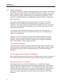
1
Model 511
10 ppm Precision DC Source/ Calibrator
Operating Manual.
Model 511
10 ppm Precision DC Source/ Calibrator
Operating Manual
Unit 4 15 Jonathan Drive, Brockton, MA 02301-5566
Tel: (508) 580-1660, Fax: (508) 583-8989
www.krohn-hite.com, e-mail [email protected]
Printed in U.S.A.
Version 1.05
Revised April 2003
Copyright © 2003 Krohn-Hite Corporation All rights reserved. No part of this publication may
be reproduced, stored in a retrieval system or transmitted in any form by any means, electronic,
mechanical photocopying, recording, or otherwise, without the prior written permission of
Krohn-Hite Corporation
Information furnished in this manual is believed to be accurate and reliable. However, no responsibility is
assumed by Krohn-Hite Corporation for its use; nor for any infringements of patents or other rights of
third parties which may result from its use.
Table of Contents
Section
1
Title
General Description and Specifications................................................................... 1-1
1-1.
1-2.
1-3.
1-4.
1-5.
1-6.
1-7.
1-8.
1-9.
1-10.
2
Introduction ............................................................................................... 1-1
Description ................................................................................................ 1-1
Safety Information..................................................................................... 1-2
Krohn-Hite Contact Information ............................................................... 1-3
Factory Calibration.................................................................................... 1-3
Specifications ............................................................................................ 1-4
Output Specifications ............................................................................. 1-4
Secondary Performance Specifications .................................................. 1-4
General Specifications............................................................................ 1-5
Options ................................................................................................... 1-6
Operation ................................................................................................................... 2-1
2-1.
2-2
2-3
2-4
2-5
3
Page
Introduction ............................................................................................... 2-1
Unpacking.................................................................................................. 2-1
Power Requirements.................................................................................. 2-2
Front Panel................................................................................................. 2-2
2-4-1
Front panel controls .................................................................. 2-2
2-4-2
Front panel indicators ................................................................ 2-3
2-4-3
Output Terminals ...................................................................... 2-3
Rear Panel.................................................................................................. 2-4
2-5-1
AC Power Entry Module ........................................................... 2-4
2-5-2
Optional Output Terminals ........................................................ 2-7
Incoming Acceptance ............................................................................................... 3-1
3-1.
3-2.
3-3.
3-4.
3-5.
3-6.
3-7.
Introduction ............................................................................................... 3-1
Recommended Test Equipment.............................................................. 3-1
Warm-up Procedure................................................................................ 3-2
DC Voltage Verification Test.................................................................... 3-2
Optional Tests............................................................................................ 3-3
DC Voltage Load Regulation Test ......................................................... 3-3
DC Voltage Output Noise Test............................................................... 3-4
i
Model 511
Operating Manual
List of Illustrations
Section
2
Title
Operation ...................................................................................................................
2-1.
2-2.
2-3.
2-4.
2-5.
2-6.
3
Page
511 Front Panel View.................................................................................2-2
Front Output Terminals ..............................................................................2-3
511 Rear Panel View..................................................................................2-4
120 Volt Line Setting Example ..................................................................2-4
Power Entry Module Exploded View ........................................................2-6
Optional Rear Output Terminals ................................................................2-7
Incoming Acceptance .................................................................................................
3-1.
3-2.
Load Regulation Setup ...............................................................................3-3
Noise Check Setup .....................................................................................3-5
List of Tables
Section
1
Title
General Description and Specifications ...................................................................
1-1.
3
Output Specifications .................................................................................1-4
Incoming Acceptance .................................................................................................
3-1.
NOTE:
Page
Output Uncertainty Check..........................................................................3-2
Errata and addendum (if any) will appear in the back of this manual
ii
Section 1
Introduction and Specifications
1-1
Introduction
This manual provides the user with the information needed to operate the Krohn-Hite
Model 511. Section 3 is a procedure used to verify that the DC Calibrator is within the
published specifications. Calibration information is included in the Krohn-Hite Model
511 Calibration manual. Details for contacting Krohn-Hite and important safety
information are also contained within this manual.
Note: If the Model 511 is still under warranty and it is outside its specified limits,
contact Krohn-Hite or your distributor to establish the course of action.
1-2
Description
The Model 511 DC Voltage Source / Calibrator is a highly versatile reference source,
designed to meet the needs of computer systems, production line testing, QC and QA
departments, design labs, and standards laboratories. The instrument has specified
accuracies traceable to the U. S. National Institute of Standards and Technology.
The Model 511 includes a "crowbar"or short circuit of the output and a true bipolar
output stage that can be floated 500 volts from chassis. Output and sense terminals are
gold plated, low thermal, safety, type, whose sense connection is selected via a front
panel 2 wire - 4 wire sense switch, that negates the need for using cumbersome shorting
links.
Resolution of each range is 1 part per million. The instrument is a highly accurate
reference that can be used for calibration of digital voltmeters, analog meters,
semiconductor analyzing systems, analog references for computers, analog-to-digital
converters, telemetry and data acquisition systems, and wherever a stable source is
required.
There are no adjustments made during normal operation. All adjustments are made
during the factory calibration. The circuitry is completely solid state made of discrete,
hybrid and/or integrated circuits packaged on etched glass circuit boards. These are
proven circuits, using derated components to insure long life and maximum reliability.
The instrument is overload and short-circuit protected, and is fully operational in normal
environmental conditions. The 511 will drive a short circuit indefinitely without damage
to the instrument, and will recover to rated specifications in less than 100µs.
1-1
Model 511
Operating Manual
1-3
Safety Information
The Model 511 has been designed, tested and supplied in a safe condition. The following
general safety precautions must be observed during all phases of operation, service, and
repair. Failure to comply with these precautions or with specific warnings elsewhere in
this manual violates safety standards of design, manufacture and intended use of this
instrument. Krohn-Hite assumes no liability for the customer's failure to comply with
these requirements.
This manual contains information and warnings that must be observed to keep the
instrument in a safe condition and ensure safe operation. Operation or service in
conditions or in a manner other than specified could compromise safety. For the correct
and safe use of this instrument, operating and service personnel must follow generally
accepted safety procedures.
To avoid injury or fire hazard, do not switch on the instrument if it is damaged or
suspected to be faulty. Do not use the instrument in damp, wet, condensing, dusty or
explosive gas environments.
Whenever it is likely that safety protection has been impaired, make the instrument
inoperative and secure against any unintended operation, and then inform qualified
personnel. Safety protection is likely to be impaired if, for example, the instrument
shows visible damage, or fails to operate normally.
Ground the Instrument
To minimize shock hazard, the instrument chassis and cabinet must be connected to an
electrical ground. Any interruption of the protective ground conductor inside or outside
the instrument is likely to make the instrument dangerous. Intentional interruption is
prohibited.
Do Not Operate In an Explosive Atmosphere
Do not operate the instrument in the presence of flammable gases or fumes. Operation of
any electrical instrument in such an environment constitutes a definite safety hazard.
Keep Away From Live Circuits
Operating personnel must not remove instrument covers. Qualified maintenance
personnel must make component replacement and internal adjustments. Under certain
conditions, dangerous voltages may exist. To avoid injuries, always disconnect input
voltages before removing the covers. Use caution when working with voltages above 30
Vac rms, 42 V peak, or 60 Vdc. These voltages pose a shock hazard A good safety
practice is to expect that hazardous voltage is present in any unknown circuit before
measuring.
1-2
General Description and Specifications
Safety Information
Do Not Substitute Parts or Modify Instrument
Because of the danger of introducing additional hazards, do not install substitute parts or
perform any unauthorized modifications. Use only the replacement fuse(s) listed in this
manual. Return the unit to the Krohn-Hite Service Department to modify or repair the
instrument to ensure that safety features are maintained.
Do Not Operate a Damaged Instrument
Whenever it is possible that the safety protection features built into this instrument have
been impaired, either through physical damage, excessive moisture, or any other reason,
REMOVE the POWER and do not use the instrument until safe operation can be verified
by service-trained personnel. If necessary, return the instrument to the Krohn-Hite
Service Department for service and repair to ensure that the safety features are
maintained.
1-4
Krohn-Hite Contact Information
To order parts, accessories, or obtain service call:
1-508-580-1660
Or, visit the Krohn-Hite Web site at www.krohn-hite.com
1-5
Factory Calibration
When manufactured, all 511’s are aged, calibrated and thoroughly verified with test
equipment and calibration standards that are traceable to the U.S. National Bureau of
Standards. Included with each shipment is a certificate of calibration.
A performance verification procedure is provided in section three. This procedure can be
used to make certain that the calibrator is with-in specifications. Verification is usually
preformed when you first take delivery of the calibrator to make sure that there was no
shipping damage, when you have questions about the calibrator’s accuracy, or after
calibration
Krohn-Hite Corporation recommends that the Model 511 be calibrated yearly at KrohnHite’s service center to sustain factory new performance. All calibrators returned to the
factory for calibration have pre and post calibration data recorded. This allows a
performance history file to be complied for each unit. Minor updates are installed (if any
are available) during recalibration
1-3
Model 511
Operating Manual
1-6
Specifications
Prior to shipment, the Model 511 calibrators are calibrated and data is recorded to
guarantee that the unit is operating with-in specifications. Output Specifications listed
below are absolute accuracies and are traceability to N.I.S.T.
1-7
Output Specifications
The output uncertainty specifications apply after a one hour warm-up under standard
reference conditions of 23ºC ± 1ºC and <70% relative humidity.
Range
Resolution
(1ppm)
Full Scale
Absolute Accuracy
(1 year)
100mV
±111.1110 mV
100 nV
±(10ppm of setting + 2µV)
1V
±1.111110 V
1 µV
±(10ppm of setting + 6µV)
10V
±11.11110 V
10 µV
±(10ppm of setting + 42µV)
Table 1-1 Output Specifications
Note: The specifications listed above are valid for one year calibration cycle.
1-8
Secondary Performance Specifications
Stability:1
24 hrs, ± (2ppm of setting +1µV)
Temperature Coefficient:
0º C to 10ºC, ± (3ppm of setting +2µV)/ºC
10º C to 40º C, ± (2ppm of setting +1µV)/ºC, typ ± 1ppm/ºC
Noise and Ripple (0.1Hz to 100kHz):
100mV and 1V range, 5µV rms; typ < 3µV rms
10V range, 10µV rms; typ < 5µV rms
Low Frequency Noise (0.1Hz to 10Hz):
2µV p-p.
Maximum Load:
100mA all ranges.
1
Stability specifications apply after initial stabilization of one hour, constant ambient
temperature ± 1ºC , constant line and load.
1-4
General Description and Specifications
Secondary Performance Specifications
Output Impedance:
10 µȍ.
Line Regulation:
± (1ppm of range +1 µV) for a ± 10 % line fluctuation.
Load Regulation:
± 1µV no load to full load.
Settling Time:
< than 100ms to settle to within 5ppm of final value.
1-9
General Specifications
Calibration Interval:
1 year for 10ppm accuracy.
Warm-up Time:
1 hour to rated accuracy.
Output Isolation:
Output may be floated 500V from chassis
Power Requirements:
105-125 or 210-250 Volts ac, single phase, 50-400 Hz, 20 watts max.
Temperature:
Calibration Temperature: 23ºC ±1ºC
Operating Limit:
0ºC to 50ºC 2
Storage Temperature:
-40ºC to 85ºC
Dimension:
3.5"(9cm) high, 14"(36cm) wide, 12.5"(32.1cm) deep.
Weight:
12 lbs(5.4kg) net; 14 lbs(6.3kg) shipping.
Certification:
A Certificate of Compliance is issued with each new instrument to certify the calibration
traceable to the National Institute of Standards and Technology (N.I.S.T.).
2
Accuracy is derated above 40º C due to loss of oven control.
1-5
Model 511
Operating Manual
Warranty:
Full one year warranty on parts and labor and a full one year warranty on specifications
and performance.
Extended warranty:
Part No. EW511 provides an additional one year to the standard warranty
1-10 Options
Rack Mount Kit:
Part number RK-314 permits installation of the model 511 into a standard 19" rack.
Rear Output Terminals:
Option 003 provides both front and rear output terminals. Note that only one set of output
terminals may be used at one time.
CE Output Terminals:
Option 004 Provides CE safety type output terminals.
1-6
Section 2
Operation
2-1
Introduction
This section describes the basic operation of the Model 511. It includes the proper ac
power requirements along with details of all operating modes and any special features. .
----- Warning ----The chassis of this instrument is connected to ground. For safety
purposes, connect the line cord to a grounded 3-terminal ac outlet.
The information in this section is intended only for qualified service
personnel Do not attempt these procedures unless you are qualified to
do so.
----- Caution ----Because of the potentially dangerous voltages that exist within the
instrument, the covers of the Model 511 should not be removed when
connected to an ac power source.
The Model 511 is adjusted and checked carefully before shipment to ensure that the unit
meets all specifications. It is aged and final tested to ensure that it is ready for use. The
unit is shipped complete.
2-2
Unpacking
Unpack the Model 511 carefully and inspect it for any damage that may have occurred
during shipment. Check the case for damage, and check for loose sub-assemblies and
parts.
2-1
Model 511
Operating Manual
2-3
Power Requirements
The Model 511 is designed to operate from a single phase, 50-60Hz ac power source of
105V-132V or 210V-250V. The ac Power Entry Module, located on the rear panel,
contains the main line fuse, an input line voltage selector, and an EMI filter. A
detachable, 3-wire line cord is provided with the instrument. The 511 is normally shipped
configured to the proper line voltage. To change settings, refer to section 2.5.1 for
instructions.
2-4
Front Panel
Figure 2.1 511 Front Panel View
2-4-1 Front Panel Controls
Power switch: A two position switch supplies power to the Model 511.
“Sense” Switch: This switch has two positions. In the "2 Wire" position, only the
instrument's output terminals are connected, the sense terminals are connected to the
output terminals internally. This position is used with high impedance loads. In the "4
Wire" position the user must connect both the sense and output terminals together at the
load. This position is used to prevent "IR" wiring losses when drawing current.
"Lo" switch: This switch has two positions. In the "Float" position the low output
terminal is floating from chassis. In the "Chassis" position the low output terminal is
connected to chassis ground.
Decade Switches: There are six. Each one controls one decade of output magnitude, and
is selectable from 0 to 10.
Range Switch: A three position switch selecting one of the three voltage ranges: 100
mV, 1 V, or 10 V.
2-2
Operation
Front Panel Controls
Polarity Switch: This switch also has three positions. "+" polarity denotes that the red
output terminal is positive with respect to black output terminal, and vice versa for "-"
polarity. The "0" position produces a "crowbar" or short circuit "0" at the output
terminals.
2-4-2 Front Panel Indicators
Power On Indicator: The Green led is on whenever the 511 is plugged into an AC power
source and the power switch is in the on position.
Decimal Point Indicators: A "floating" decimal point is illuminated by several yellow
LEDs and properly locates the decimal point for the range indicated.
Overload Indicator: When illuminated, indicates an overload or possibly shorted
condition (excessive current draw), or an open sense circuit condition.
2-4-3 Output Terminals
Front Panel Connections: There are five terminals located on the front panel. All
terminals are low thermal, gold plated type. Spacing is the standard 3/4" centers.
Connections are located as follows:
HIGH SENSE
o
m HIGH OUTPUT
LOW SENSE
o
m LOW OUTPUT
m CASE GROUND
Figure 2.2 Front Output Terminals
The "output" and "sense" refers to the 4-wire remote sense capability. This 4-wire system
eliminates the IR drop and thus maintains the voltage accuracy, of the Model 511.
NOTE: The "sense" circuit must be connected to the
load when the 511 is used in 4-wire mode.
2-3
Model 511
Operating Manual
2-5
Rear Panel
Figure 2.3 511 Rear Panel View
2-5-1 Power Entry Module
The 511 will operate on 100, 120, 220 or 240 Vac line voltage. The following explain
how to change the voltage settings and the fuse. The cover of the Power Entry Module
shows four possible voltage settings (100V, 120V, 220V or 240V). Notice that a pin will
be in one of these holes, indicating the present voltage setting for the 511. If this setting
does not match the voltage available at your site, then it must be changed before
powering on the 511. Figure 2.4 shows an example setting for 120 Vac operation.
Figure 2.4 120 Volt Line Setting Example
Follow the steps below to change a fuse or convert the operating voltage of a 511.
2-4
Operation
Power Entry Module
Set the 511 power switch to OFF. Unplug the power cord from the ac wall outlet and
from the power cord receptacle on the power entry module. Refer to Figure 2-5 on the
next page.
Using a small flat blade screwdriver or similar tool inserted into the slot at the left edge
of the cover, carefully pry the cover off the fuse cavity. To change the voltage setting,
grasp the white plastic voltage select board pin and pull straight outward until the voltage
select board unseats from the power entry module. Hold the board so that you can read
the four voltage selection labels (100, 120, 220 and 240) imprinted on the board. Move
the voltage indicator pin to the opposite side of the board from the desired voltage label.
Be sure to seat the pin in the notch provided on the board's edge. Install the voltage
select board so that it is fully seated in the voltage select cavity (the label side toward the
fuse cavity).
To change the fuse (s), remove the fuse (s) from the fuse carrier on the back of the cover.
For 100 or 120 Vac operation, the fuse rating is 1/8 Amp, Slow-Blow. For 220 or 240
Vac operation, the fuse rating is 1/16 Amp, Slow-Blow. Be sure to use the correct rating
for your voltage selection. For installation, insert the fuse(s) of the proper rating into the
fuse carrier. To change the fuse arrangement to match that used in your country, remove
the screw from the fuse carrier, remove the fuse carrier, turn the fuse carrier so that the
desired fuse arrangement (single fuse or dual fuses) is facing outward, install the fuse
carrier, and install the screw. For United States type power operation, use a single
standard AGC or 3AG 0.25 inch x 1.25 inches fuse of the correct rating. For European
type power operation, use two standard 5.2 mm x 20 mm fuses of the correct rating. For
European use, is important to note that if your local electrical code does not allow a dual
fuse arrangement, then a dummy fuse must be installed in the lower fuse carrier.
Otherwise, the 511 will not operate. Place the cover on the power entry module and press
inward until it snaps into place. Verify that the desired operating voltage is indicated with
the voltage select board pin on the cover label. Connect the power cord to the power
entry module and wall outlet.
The Model 511 is now ready to be operated on the selected ac line voltage.
2-5
Model 511
Operating Manual
Figure 2.5 Power Entry Module
2-6
Operation
Optional Output terminals
2-5-2 Optional Output Terminals
Rear Panel Connections: A factory installed option, there are five terminals located on the
rear panel. The configuration is the same as the front panel terminals. Figure 2.6 below
shows the connections.
NOTE: Only one set of output terminals may be used at one time.
o
m HIGH SENSE
o
m LOW SENSE
HIGH OUTPUT
LOW OUTPUT
CASE GROUND
o
Figure 2.6 Optional Rear Output Terminals
2-7
Model 511
Operating Manual
Notes:
2-8
Section 3
Incoming Acceptance
3-1
Introduction
The following procedure should be used to verify that the Model 511 is operating properly. These
checks may be used for incoming acceptance and periodic performance checks. Test should be
made with the covers in place and after a one hour warm-up under standard reference conditions
of 23ºC ± 1ºC and <70% relative humidity.
----- Warning ----The chassis of this instrument is connected to ground. For safety
purposes, connect the line cord to a grounded 3-terminal ac outlet.
The information in this section is intended only for qualified service
personnel Do not attempt these procedures unless you are qualified to
do so.
----- Caution ----Because of the potentially dangerous voltages that exist within the
instrument, the covers of the Model 511 should not be removed when
connected to an ac power source.
3-2
Recommended Test Equipment
The equipment listed below is required to perform the acceptance tests.
Digital Voltmeter: H-P Model 3458A or equivalent.
Power Load Resistor: CLAROSTAT Model 240-C or equivalent.
High gain differential preamplifier such as PREAMBLE Model DA1822A or equivalent.
True rms voltmeter having a 20mV range: Fluke Model 8920A or equivalent.
3-1
Model 511
Operating Manual
3-3
Warm-up Procedure
Perform your verification measurements in a test environment that has a stable ambient
room temperature with a relative humidity of less than 70% unless noted otherwise. The
Model 511 requires a power line voltage of 100V, 120V, 220V, 240V, ±10% with a line
frequency of 50Hz to 400Hz
Allow the minimum warm up time for all test equipment. The Model 511 needs at least
one hour to stabilize. Additional time will be needed if the instrument has been subjected
to temperatures outside the 18-28°C range.
3-4
DC Voltage Verification Test
After allowing sufficient warm up time, connect the DC voltmeter to the output terminals
of the model 511. The front panel “SENSE” switch should be in the 2-wire position and
the “LO” switch should be in the float positions. The chart below lists the 511 settings
along with the test limits.
Uncertainty Check
Range
10V
1V
100mV
D.P.
LED
on
V
0.V
mV
Polarity
Front Panel Decade
Switch Setting
Low Limit
Upper Limit
+
10
0
0
0
0
0
+ 9.999858 V
+10.000142 V
-
10
0
0
0
0
0
- 9.999858 V
-10.000142 V
+ or -
0
0
0
0
0
0
+
10
0
0
0
0
0
+ 0.999984 V
+ 1.000016 V
-
10
0
0
0
0
0
- 0.999984 V
- 1.000016 V
+ or -
0
0
0
0
0
0
+
10
0
0
0
0
0
+ 99.997 mV
+ 100.003 mV
-
10
0
0
0
0
0
- 99.997 mV
- 100.003 mV
+ or -
0
0
0
0
0
0
± 42 µV
± 6 µV
Table 3.1 Output Uncertainty Check
3-2
± 2 µV
Verification
Optional Tests
3-5
Optional Tests
These procedures are used to ensure that the Model 511 passes both the 4-wire load
regulation and the output noise tests.
3-6
DC Voltage Load Regulation Test
Connect the DC voltmeter to the sense and output junction on the Power Load Resistor
box.3 Set the 511 to 4-wire mode and connect the load box to the 511 with two 2-wire
twisted pair cables. The 511 sense and output terminals must be connected at the load
box. Refer to figure 2.1 for hookup details.
Load Box
Model 511
SENSE OUT
HI
LO
Voltmeter
IN
Figure 3-1 Load Regulation Setup
Set the 511 to output 10.00000 volts and set the load box to a few hundred thousand
ohms (light load). After noting the voltmeters reading, reduce the load resistance to 100
ohms and record the voltmeter new reading. The change should be less than ± 1µV.
Change to the 1 V range and repeat the test using 10 ohms for the second setting. The
change should be less than ± 1µV.
Change to the 100 mV range and repeat the test using 1 ohms for the second setting. The
change should be less than ± 1µV.
3
The voltmeter must be connected to the sense leads at the junction of where the 511's output
and sense cables connect at the load.
3-3
Model 511
Operating Manual
3-7
Output Noise Test
KH uses the following procedure to measure the noise levels of the voltage calibrator.
Techniques are employed to minimize external ground loops and radiation paths that may
introduce improper data into the desired measurements. "Rule of Thumb": If the
measurement indicates more than 1 millivolt p-p of noise on any KH instrument, the
operator should recheck his equipment, cables and connections.
Noise may appear in many forms; therefore KH recommends the use of a true rms
voltmeter with a 20mV range and a high gain (1000) differential pre-amplifier to make
the noise measurements. The high gain differential pre-amplifier specified will increase
the sensitivity of the true rms voltmeter, enabling it to resolve noise levels in the µV
level.
The noise test should not be made simultaneously with regulation and voltage accuracy
test. The "feedback" currents from some measuring devices will seriously disturb noise
measurements.
Differential input measurements are the most reliable. They will cancel out common
mode, due to slight errors in cable connections.
The pre-amplifier, true rms voltmeter and the KH Calibrator under test should be
connected to adjacent power outlets on the same phase. A three wire ground is required.
In the event the line does not have a ground, the pre-amplifier and unit under test should
have a separate, heavy wire chassis-to-chassis connection separate from the shield of the
differential input leads. The lead used between the pre-amplifier input and the source
output should be a shield, twisted pair with the shield connected to the frame of the preamplifier, and to the chassis ground terminal adjacent to the output terminals of the KH
source. Do not use the shield of the input cable as the chassis-to-chassis connection in
place of line system ground. Use additional separate heavy wire. Refer to Figure 2.2 on
the next page for correct connections.
3-4
Verification
Output Noise Tests
Pre-amplifier
Model 511
SENSE OUT
+
Input
-
Output
CHASSIS
Voltmeter
IN
Figure 3.2 Noise Check Setup
Set the differential pre-amplifier upper frequency cutoff to100kHz and the lower cutoff to
0.1Hz. Set the model 511 “sense” switch to the “2-Wire” position and the output to zero.
Connect the output of the pre-amplifier to the input of the true rms voltmeter. Observe
that ripple and noise do not exceed specifications on each of the ranges. The limit is 5µV
rms on both the 100mV and 1V range; and 10µV rms on the 10V range.
NOTE: The "DC" mode on the preamp in use usually results in more accurate
"noise" measurements. Be aware of the specifications for your preamp if this test is
made at voltage levels other than zero, and AC input is used.
3-5
Model 511
Operating Manual
Notes:
3-6