1
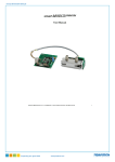
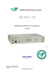
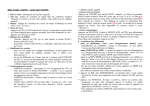
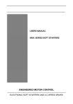
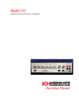
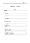
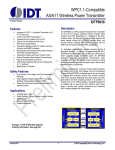
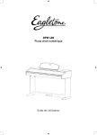
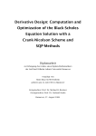
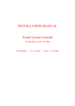
LS-30 Low Noise Switch +/-15V Range LS_30_User_Manual_1_2.doc 11 - Nov. - 2015 Data Sheet & User Manual Rev. 1.2 Model Number LS-30 Triple www.stahl-electronics.com LS-30 User Manual, Rev .1.2 TABLE OF CONTENTS 1. Safety Hints ………………………………….…………………………………… 3 2. General Information and Overview………………….………………………….. 2.1 Purpose and Description of the Device…………………………….. 2.2 Functional Principle and Block Diagram…………………………. 4 4 4 3. Installation ……………………………………………………………………..… 6 3.1. Mechanical and Electrical Installation……………………………… 6 4. Operation and Control Elements ……………………………………………….. 7 4.1 4.2 4.3 Elements on the front plate………………………………………… Elements on the rear side..………………………………………… Output Characteristics……………………………………………… 7 7 8 5. Maintenance………………………………………….…………………………. 11 6. Specifications……………………………………………………………………. 12 Declaration of Conformity ………………………………………………………… 13 2 www.stahl-electronics.com phone: +49 6242-504882, fax: +49 6242 504884 LS-30 User Manual, Rev .1.2 1. Safety Hints Read all installation, operation, and safety instructions Rear side switch turns device completely off This equipment must be connected to an earth safety ground Do not modify the unit Change cabling only when device is off Do not operate in wet/damp conditions Beware of external magnetic fields Service is to be performed by qualified service persons only Do not block chassis ventilation openings Routinely cleaning from dust No outdoor operation Prior to operation, thoroughly review all safety, installation, and operating instructions accompanying this equipment. If the device is not in use for a longer time, it is recommended to turn the mains switch at rear side off. This product is grounded through the grounding conductor of the power cord. To avoid electrical hazard, the grounding conductor must be connected to protective earth ground. Do not make electrical or mechanical modifications to this unit. Changing the cabling, when voltages are present at the outputs can lead to formation of harmful sparks. To avoid electric shock hazard, do not operate this product in wet or damp conditions. Protect the device from humidity and direct water contact. External magnetic fields can impair, damage or even destroy this device. A maximum external field strength of no more than B = 10mT is admissible. Having placed the device at any time into an external magnetic of bigger B = 10mT (regardless if power was turned on or off) can lead to severe overheating of the device and severely increased hazard of fire. All servicing on this equipment must be carried out by factory-qualified service personnel only. Slots and openings in the chassis are provided for ventilation purposes to prevent overheating of the equipment and must not be restricted. All case vents should continuously be cleared (fan inlet at rear side, air outlet at rear side), in order to prevent overheating. After long operation, or operation in a dusty environment it is strongly recommended to have the internal parts of the device cleaned by the manufacturer, or an appropriately qualified workshop in order to reduce the hazard of overheating. Outdoor operation of the device is not admissible. 3 www.stahl-electronics.com phone: +49 6242-504882, fax: +49 6242 504884 LS-30 User Manual, Rev .1.2 2. General Information and Overview 2.1 Purpose and Description of the Device Purpose of the LS-30 devices is the fast switching of electrodes, electrostatic lenses, beam deflectors or ion traps. Unlike DC power switches, the outputs expect capacitive loads in the 100pF range. The outputs are optimized for high stability and very low noise. The switches are housed in standard 19inch rack-mount cases. They are available in single-channel to triple channels versions. Individual switches are completely independent except that they share a common GND. fig 2.1: front view of a LS-30 device (triple version) 2.2 Functional Principle and Block Diagram The following scheme displays a block diagram of the internal structure and illustrates the functional principle. The control input (BNC socket on front plate) defines the position of the internal high voltage switch, which connects either input A or input B to the output. A digital signal (TTL/CMOS level 0V/5V) may be applied to this control input. A three-position manual switch on the front side allows to override the digital control signal. The switching elements inside the device are implemented as MOSFET-transistors, allowing fast switching transitions in the order of 20ns and less. fig 2.2: Block diagram of a LS-30 device. Inside the triple version, the scheme exists three times, i.e. there are three independent switches. Unlike high voltage pulse-generators the internal switch circuitry is implemented as fast static switch, which means that the applied control input level defines the (static) switch position as illustrated in the scheme above. The output is connected to the selected input by a (transistor based) resistor. The nonselected input is isolated from the output by a high isolation resistance. The input range for both inputs A and B is -15V to +15V each. Either polarity is applicable. In case the latter voltage is exceeded for a short time, it will be clamped to approx. +/-16V. Note that voltages 4 www.stahl-electronics.com phone: +49 6242-504882, fax: +49 6242 504884 LS-30 User Manual, Rev .1.2 being substantially higher that +/-15V, which are permanently applied to an input or output, will damage the device. Application example: Generation of 500µs-duration positive-going 30Volt-pulse The subsequent oscilloscope screen shot shows a typical application example. A control pulse of logic level (high = 5V, low = 0V) is applied to the control input. Inputs B and A were provided with an external voltage of -15V and +15V respectively. At the edges of the control signal the switch is triggered, and switches from -15V to +15V and after 500µs back to -15V. Trace 2 shows the control signal, being used to trigger the switch. A rectangular pulse results, with steep slopes and constantvoltage static levels. For further details on the slope of the waveforms see section 4.3 fig 2.3: Oscilloscope traces of a positive pulse, t = 500s duration. The green trace shows the digital control signal, the blue shows the output signal. Oscilloscope: Rigol DS1302 CA, capacitive load: 100pF 5 www.stahl-electronics.com phone: +49 6242-504882, fax: +49 6242 504884 LS-30 User Manual, Rev .1.2 3. Installation 3.1. Mechanical and Electrical Installation Positioning: Provide sufficient air cooling of the device and locate it in normal horizontal position to allow for defined air convection. Rack mounting into a standard 19” rack is possible as well as resting the device on a table. If mounted in a rack, please make sure that all case vents are permanently cleared (fan inlet at rear side, air outlets at rear side), in order to prevent overheating. fig. 3.1: Keep air vents always cleared to ensure sufficient ventilation Beware of external magnetic fields: Strong external magnetic fields can impair, damage or even destroy this device (e.g. proximity to a superconducting magnet). A maximum external field strength of no more than B = 10mT is admissible. Not observing this important limit can lead to severe overheating of the device and increases the hazard of fire. Connecting to mains power: Connect the device to the mains power supply (220 to 240V ac) by using an appropriate power cord, being properly wired and providing a grounded outlet. The power cord must be suited with respect to possible load currents and should be rated to 2A current. Cabling of voltage outputs: Always provide appropriate and safe cabling when connecting the device to other devices or vacuum/experimental setups. Cabling is preferred using coaxial cable with proper shielding. BNC connector cables are a suitable choice in order to ensure proper shielding against external noise pickup and in order to provide protective ground for safety reasons. 6 www.stahl-electronics.com phone: +49 6242-504882, fax: +49 6242 504884 LS-30 User Manual, Rev .1.2 4. Operation and Control Elements 4.1 Elements on the front plate mains supply switch Switch 1 ext. / manual Switch 2 ext. / manual Switch 3 ext. / manual fig. 4.1: front plate elements The front plate contains the control elements of the device. It is powered up after turning on the rearside mains supply switch and also the power button on the front plate. The Power-on-LED (green) indicates proper operation of the internal circuitry. fig. 4.2: manual switch, BNC input and LED indicators. Each channel features a three-position manual switch (fig. 4.2). Lifted upwards, the output (rear side) is connected to the input A, moved into lower position it connects the output to input B. In the center position of this switch the control voltage, being applied to the BNC input, defines the switch position. A high level connects the output with A, low level connects to B. Common 5V / 0V signal may be applied to this BNC control input. In practical cases a PC controlled Delay-Gate generator or function generator is often connected to this BNC input. The LS-30 device is rated for input voltages (inputs A and B up to +/-15V DC vs. GND) The LED indicators on the right hand side show the switch status, indicating which input (A or B) is connected to the output. 4.2 Elements on the rear side fig. 4.3: rear side elements (a triple channel version is shown) The rear side of the device contains the ventilation elements, 230V supply connector, power on/off switch (with fuses) and the switch inputs and outputs. fig. 4.4: BNC and 4mm sockets for inputs and BNC output, fuse sockets 7 www.stahl-electronics.com phone: +49 6242-504882, fax: +49 6242 504884 LS-30 User Manual, Rev .1.2 Fig. 4.4 shows the BNC sockets for the two input voltages A, and B and the switch output OUT. Alternatively the input voltages can be applied to the two red 4mm laboratory sockets, for which the black center socket serves as GND input. The fuse sockets shown in fig. 4.4 contain safety fuses for the two inputs. In case extensive currents flow, they may blow. Nominal rating is 0.5 Ampere, fast blow. All voltages must reside in the interval between -15V and +15V to avoid damage to the device. Please note that the capacitive load on the output may impair the switching speed performance. Nominal loads from 0pF to 300pF may be connected. See also next section for waveforms traces. 4.3 Output Characteristics Dynamic Response As soon as the internal switch connects either input A or B to the output, the latter assumes the voltage on the respective input. There is a time constant related to each voltage transition, essentially given by the internal switch resistance (approx. 150 ), the internal output current limit (approx. ±250mA) and the capacitive load on the output, including all cables to an experimental setup. In case of BNC cables one may count about 100pF per meter cable length, therefore extensively long cables should be avoided. The following oscilloscope traces show voltage step transitions observed at the output with a medium capacitive load (100pF) for further illustration. fig. 4.5 (left frame) negative voltage step of 30V from +15V to -15V with medium capacitive load (C = 100pF) at the output; (right frame) positive voltage step of 30V with the same capacitive load; transient rise time (10% to 90% of voltage step size) is in the order of 22ns in each case. Oscilloscope: Rigol DS1302 CA, 300MHz bandwidth. Green trace: control signal; blue trace: output signal. Noise and Ripple In contrast to other devices, based on switched circuit / power switching technology, the HS series devices feature a very low noise level. This makes them specially suited for ion traps, low energy beam line applications or medical sensors. Each output exhibits a very low broadband noise (DC to 20MHz) of smaller than 5µVrms and a low ripple level (50Hz) in the order of 4µVrms. In general the outputs are completely free of parasitic switching spikes in the RF region. The subsequent graphs show further details regarding observed waveforms and noise densities. 8 www.stahl-electronics.com phone: +49 6242-504882, fax: +49 6242 504884 LS-30 User Manual, Rev .1.2 fig. 4.6: Output signal being observed using a 200V/V preamplifier and digital oscilloscope, while input being switched to GND. A statistical signal is visible and an additional 50Hz Ripple of about 4µVrms, or 15µVpp. A 60kHz low pass filter was used to define the frequency window of this measurement (i.e. DC to 60kHz). The displayed span on Y-axis is 42µV. fig. 4.7: Recorded trace of same configuration as in figure 4.6, but faster time scale. A statistical signal is visible of approx. 5µVpp amplitude. 9 www.stahl-electronics.com phone: +49 6242-504882, fax: +49 6242 504884 LS-30 User Manual, Rev .1.2 fig. 4.8: Wide band voltage noise density (600 Hz to 2.5MHz) observed at output, while input being switched to GND, i.e. shorted (lower trace, green) or connected via 33kOhms to GND (upper trace, blue). Measurement device: PicoScope3224 in FFT mode with x80 preamplifier. The green curve is essentially flat, corresponding to an underlying level of approx. 9nV/√Hz, while the green trace related to a 33kOhm termination is higher due to the thermal noise of the 33kOhm resistor (expected: 24nV/√Hz) and other parasitic current noise contributions. 10 www.stahl-electronics.com phone: +49 6242-504882, fax: +49 6242 504884 LS-30 User Manual, Rev .1.2 5. Maintenance The LS-30 switches are designed for years of reliable operation. Under normal operating conditions, they should not require electrical maintenance, except routine cleaning of dust. Exchange of ventilation fan is strongly recommended every 50’000 operation hours (see below). If any question should arise, please contact the manufacturer. Routine cleaning All ventilation openings should be checked periodically and kept free of dust and other obstructions. A vacuum cleaner may be used to clean these vents when the unit is powered off. The front panel may be cleaned periodically with a clean cloth and mild alcohol solution, when the unit is powered off. It is recommended to send the device to the manufacturer routinely in 4-year intervals for internal cleaning from dust. Fan life time and temperature monitoring The air ventilation fan is a part which shows unavoidable deterioration in time. Exchange of this part is strongly recommended after 50´000 hours of operation. Please contact manufacturer for replacement. Complete failure can lead to overheating of the device. Several temperature fuses and other protection measures provide a certain degree of safety against fire hazard in this case. Fire hazard Please note that excessive accumulation of dust inside the case of the device can lead to overheating. This, together with possible discharges increases the risk of fire, caused by electrical sparks. Routinely cleaning the device from dust minimizes this risk. It is therefore recommended to send the device to the manufacturer routinely in 4-year intervals for internal cleaning from dust, or to have it cleaned by an accordingly qualified electronical workshop. Also air conditions containing oil mists (e.g. in proximity to a vacuum pump or mechanical machines) place a severe danger, since inflammable substances could enter the device through the ventilation holes. If in doubt, cleaning by an accordingly qualified electronical workshop or the manufacturer is strongly recommended. An increased hazard of fire may also occur if the device has been (permanently or temporarily) located in proximity to a strong (e.g. superconducting) magnet. A maximum external field of B = 10mT is admissible. 11 www.stahl-electronics.com phone: +49 6242-504882, fax: +49 6242 504884 LS-30 User Manual, Rev .1.2 6. Specifications Control Input required drive level typ. 0V and 5V threshold input impedance 2.4V 1k // 6pF Output Switch, static static resistance from A or B to OUT “on”-state isolation resistance from A or B to OUT leakage currents from A or B to OUT intrinsic switch capacitance on OUT terminal Noise Transfer characteristics delay from control input change to output reaction delay jitter max. pulse duration min. pulse duration Output rise or fall time, 10% to 90% step size 150 3nA 25pF to 35pF Operating Humidity & Temperature Case dimensions 15nA voltage differences from A or B to OUT smaller or equal 15V voltage differences from A or B to OUT smaller or equal 15V < 10µVrms DC to 20MHz 30V output step size (positive or negative going) T = 25°C +/-1°C 160ns 1ns rms infinite 0 22ns capacitive load of 100pF +/-15V both polarities may be applied vs. GND fuse replaceable on rear side max. 10 mT Bmax must never be exceeded -55 C° to +85 C° noncondensing relative humidity up to 95% between temperatures of +10°C and +35°C. AC input voltage 230VAC at 50Hz. The power entry module is EMI/RFI-filtered. Fuse: medium fast blow 1.0A Power Supply Power Consumption IOUT < 50mA 200mA medium-fast Environmental Conditions Magnetic Field Storage Temperature Conditions and remarks 180 >50M Input Voltage Rating Input A or B vs. GND Fuse rating max. -2V to +6V vs. GND 3.4W 19.00” wide x 10” deep x 1 height unit. Front-panel mounting holes are configured for M6 rack configurations weight approximately 1.2kg 12 www.stahl-electronics.com phone: +49 6242-504882, fax: +49 6242 504884 LS-30 User Manual, Rev .1.2 DECLARATION OF CONFORMITY Manufacturer's Name: Dr. Stefan Stahl - Electronics for Science and Research - Manufacturer's Address: Kellerweg 23 67582 Mettenheim Germany. Declares, that the product Product Name: Model Number: fast Low-Noise Signal Switch LS-30 LS-30 Product Options: This declaration covers all options of the above product(s) Conforms with the following European Directives: The product herewith complies with the requirements of the: 1. Low Voltage Directive 73/73EEC; 2. EMC Directive 89/336/EEC (including 93/68/EEC) and carries the CE Marking accordingly Date Of Issue __________________ 18. Sept. 2012 General Director 13 www.stahl-electronics.com phone: +49 6242-504882, fax: +49 6242 504884