1
TI DSP/BIOS Real-time Operating
System v6.x User’s Guide
Literature Number: SPRUEX3D
October 2009
IMPORTANT NOTICE
Texas Instruments Incorporated and its subsidiaries (TI) reserve the right to make corrections, modifications, enhancements,
improvements, and other changes to its products and services at any time and to discontinue any product or service without notice.
Customers should obtain the latest relevant information before placing orders and should verify that such information is current and
complete. All products are sold subject to TI's terms and conditions of sale supplied at the time of order acknowledgment.
TI warrants performance of its hardware products to the specifications applicable at the time of sale in accordance with TI's standard
warranty. Testing and other quality control techniques are used to the extent TI deems necessary to support this warranty. Except
where mandated by government requirements, testing of all parameters of each product is not necessarily performed.
TI assumes no liability for applications assistance or customer product design. Customers are responsible for their products and
applications using TI components. To minimize the risks associated with customer products and applications, customers should
provide adequate design and operating safeguards.
TI does not warrant or represent that any license, either express or implied, is granted under any TI patent right, copyright, mask
work right, or other TI intellectual property right relating to any combination, machine, or process in which TI products or services
are used. Information published by TI regarding third-party products or services does not constitute a license from TI to use such
products or services or a warranty or endorsement thereof. Use of such information may require a license from a third party under
the patents or other intellectual property of the third party, or a license from TI under the patents or other intellectual property of TI.
Reproduction of information in TI data books or data sheets is permissible only if reproduction is without alteration and is accompanied
by all associated warranties, conditions, limitations, and notices. Reproduction of this information with alteration is an unfair and
deceptive business practice. TI is not responsible or liable for such altered documentation. Information of third parties may be
subject to additional restrictions.
Resale of TI products or services with statements different from or beyond the parameters stated by TI for that product or service
voids all express and any implied warranties for the associated TI product or service and is an unfair and deceptive business practice.
TI is not responsible or liable for any such statements.
TI products are not authorized for use in safety-critical applications (such as life support) where a failure of the TI product would
reasonably be expected to cause severe personal injury or death, unless officers of the parties have executed an agreement
specifically governing such use. Buyers represent that they have all necessary expertise in the safety and regulatory ramifications
of their applications, and acknowledge and agree that they are solely responsible for all legal, regulatory and safety-related requirements concerning their products and any use of TI products in such safety-critical applications, notwithstanding any applicationsrelated information or support that may be provided by TI. Further, Buyers must fully indemnify TI and its representatives against
any damages arising out of the use of TI products in such safety-critical applications.
TI products are neither designed nor intended for use in military/aerospace applications or environments unless the TI products are
specifically designated by TI as military-grade or "enhanced plastic." Only products designated by TI as military-grade meet military
specifications. Buyers acknowledge and agree that any such use of TI products which TI has not designated as military-grade is
solely at the Buyer's risk, and that they are solely responsible for compliance with all legal and regulatory requirements in connection
with such use.
TI products are neither designed nor intended for use in automotive applications or environments unless the specific TI products
are designated by TI as compliant with ISO/TS 16949 requirements. Buyers acknowledge and agree that, if they use any nondesignated products in automotive applications, TI will not be responsible for any failure to meet such requirements.
Following are URLs where you can obtain information on other Texas Instruments products and application solutions:
Products
Applications
Amplifiers
amplifier.ti.com
Audio
www.ti.com/audio
Data Converters
dataconverter.ti.com
Automotive
www.ti.com/automotive
DLP® Products
www.dlp.com
Broadband
www.ti.com/broadband
DSP
dsp.ti.com
Digital Control
www.ti.com/digitalcontrol
Clocks and Timers
www.ti.com/clocks
Medical
www.ti.com/medical
Interface
interface.ti.com
Military
www.ti.com/military
Logic
logic.ti.com
Optical Networking
www.ti.com/opticalnetwork
Power Mgmt
power.ti.com
Security
www.ti.com/security
Microcontrollers
microcontroller.ti.com
Telephony
www.ti.com/telephony
RFID
www.ti-rfid.com
Video & Imaging
www.ti.com/video
RF/IF and ZigBee® Solutions
www.ti.com/lprf
Wireless
www.ti.com/wireless
Mailing Address: Texas Instruments, Post Office Box 655303 Dallas, Texas 75265
Copyright © 2009, Texas Instruments Incorporated
This is a draft version printed from file: pref.fm on 10/12/09
Preface
Read This First
About This Manual
This manual describes the TI DSP/BIOS Real-time Operating System. The
latest version number as of the publication of this manual is DSP/BIOS 6.21.
DSP/BIOS gives developers of mainstream applications on Texas
Instruments devices the ability to develop embedded real-time software.
DSP/BIOS provides a small firmware real-time library and easy-to-use tools
for real-time tracing and analysis.
Notational Conventions
This document uses the following conventions:
❏
Program listings, program examples, and interactive displays are shown
in a special typeface. Examples use a bold version of the special typeface
for emphasis.
Here is a sample program listing:
#include <xdc/runtime/System.h>
int main(){
System_printf("Hello World!\n");
return (0);
}
❏
Square brackets ( [ and ] ) identify an optional parameter. If you use an
optional parameter, you specify the information within the brackets.
Unless the square brackets are in a bold typeface, do not enter the
brackets themselves.
iii
Related Documentation From Texas Instruments
Related Documentation From Texas Instruments
❏
DSP/BIOS 6 Release Notes
(BIOS_INSTALL_DIR/Bios_#_#_release_notes.html).
Includes information about software version, upgrades and compatibility,
host and target device support, validation, and known issues.
❏
DSP/BIOS 6 Getting Started Guide
(BIOS_INSTALL_DIR/docs/Bios_Getting_Started_Guide.pdf).
Includes steps for installing and validating the installation. Provides a
quick introduction to DSP/BIOS.
❏
RTSC-Pedia wiki: http://rtsc.eclipse.org/docs-tip
❏
Code Composer Studio Mediawiki:
http://tiexpressdsp.com/wiki/index.php?title=CCSv4
❏
CCSv4 online help contains reference information about XDCtools and
DSP/BIOS packages and their modules, APIs, XDCtools configuration,
data structures, etc. See Section 1.5.1.
❏
Migrating a DSP/BIOS 5 Application to DSP/BIOS 6 (SPRAAS7).
(BIOS_INSTALL_DIR/docs/Bios_Legacy_App_Note.pdf)
Related Documentation
You can use the following books to supplement this reference guide:
The C Programming Language (second edition), by Brian W. Kernighan
and Dennis M. Ritchie, published by Prentice-Hall, Englewood Cliffs, New
Jersey, 1988
Programming in C, Kochan, Steve G., Hayden Book Company
Programming Embedded Systems in C and C++, by Michael Barr, Andy
Oram (Editor), published by O'Reilly & Associates; ISBN: 1565923545,
February 1999
Real-Time Systems, by Jane W. S. Liu, published by Prentice Hall; ISBN:
013099651, June 2000
Principles of Concurrent and Distributed Programming (Prentice Hall
International Series in Computer Science), by M. Ben-Ari, published by
Prentice Hall; ISBN: 013711821X, May 1990
American National Standard for Information Systems-Programming
Language C X3.159-1989, American National Standards Institute (ANSI
standard for C); (out of print)
iv
Trademarks
Trademarks
The Texas Instruments logo and Texas Instruments are registered
trademarks of Texas Instruments. Trademarks of Texas Instruments include:
TI, Code Composer, Code Composer Studio, DSP/BIOS, SPOX, TMS320,
TMS320C54x, TMS320C55x, TMS320C62x, TMS320C64x, TMS320C67x,
TMS320C28x, TMS320C5000, TMS320C6000 and TMS320C2000.
Windows is a registered trademark of Microsoft Corporation.
Linux is a registered trademark of Linus Torvalds.
All other brand or product names are trademarks or registered trademarks of
their respective companies or organizations.
October 14, 2009
Read This First
v
vi
This is a draft version printed from file: bios6ugtoc.fm on 10/12/09
Contents
1
About DSP/BIOS . . . . . . . . . . . . . . . . . . . . . . . . . . . . . . . . . . . . . . . . . . . . . . . . . . . . . . . . . . .1-1
This chapter provides an overview of DSP/BIOS and describes its relationship to XDCtools.
1.1
What is DSP/BIOS? . . . . . . . . . . . . . . . . . . . . . . . . . . . . . . . . . . . . . . . . . . . . . . . . . . . .1-2
1.2
What’s New? . . . . . . . . . . . . . . . . . . . . . . . . . . . . . . . . . . . . . . . . . . . . . . . . . . . . . . . . .1-3
1.3
How are DSP/BIOS and RTSC Related? . . . . . . . . . . . . . . . . . . . . . . . . . . . . . . . . . . . .1-4
1.4
DSP/BIOS Packages . . . . . . . . . . . . . . . . . . . . . . . . . . . . . . . . . . . . . . . . . . . . . . . . . . .1-6
1.5
For More Information . . . . . . . . . . . . . . . . . . . . . . . . . . . . . . . . . . . . . . . . . . . . . . . . . . .1-7
2
Threading Modules . . . . . . . . . . . . . . . . . . . . . . . . . . . . . . . . . . . . . . . . . . . . . . . . . . . . . . . . .2-1
This chapter describes the types of threads a DSP/BIOS program can use.
2.1
DSP/BIOS Startup Sequence. . . . . . . . . . . . . . . . . . . . . . . . . . . . . . . . . . . . . . . . . . . . .2-2
2.2
Overview of Threading Modules. . . . . . . . . . . . . . . . . . . . . . . . . . . . . . . . . . . . . . . . . . .2-4
2.3
Hardware Interrupts . . . . . . . . . . . . . . . . . . . . . . . . . . . . . . . . . . . . . . . . . . . . . . . . . . .2-15
2.4
Software Interrupts . . . . . . . . . . . . . . . . . . . . . . . . . . . . . . . . . . . . . . . . . . . . . . . . . . . .2-24
2.5
Tasks . . . . . . . . . . . . . . . . . . . . . . . . . . . . . . . . . . . . . . . . . . . . . . . . . . . . . . . . . . . . . .2-43
2.6
The Idle Loop . . . . . . . . . . . . . . . . . . . . . . . . . . . . . . . . . . . . . . . . . . . . . . . . . . . . . . . .2-61
2.7
Example Using Hwi, Swi, and Task Threads . . . . . . . . . . . . . . . . . . . . . . . . . . . . . . . .2-62
3
Synchronization Modules . . . . . . . . . . . . . . . . . . . . . . . . . . . . . . . . . . . . . . . . . . . . . . . . . . . .3-1
This chapter describes modules that can be used to synchronize access to shared resources.
3.1
Semaphores . . . . . . . . . . . . . . . . . . . . . . . . . . . . . . . . . . . . . . . . . . . . . . . . . . . . . . . . . .3-2
3.2
Event Module . . . . . . . . . . . . . . . . . . . . . . . . . . . . . . . . . . . . . . . . . . . . . . . . . . . . . . . . .3-8
3.3
Gates . . . . . . . . . . . . . . . . . . . . . . . . . . . . . . . . . . . . . . . . . . . . . . . . . . . . . . . . . . . . . .3-14
3.4
Mailboxes . . . . . . . . . . . . . . . . . . . . . . . . . . . . . . . . . . . . . . . . . . . . . . . . . . . . . . . . . . .3-18
4
Timing Services . . . . . . . . . . . . . . . . . . . . . . . . . . . . . . . . . . . . . . . . . . . . . . . . . . . . . . . . . . . .4-1
This chapter describes modules that can be used for timing purposes.
4.1
Overview of Timing Services . . . . . . . . . . . . . . . . . . . . . . . . . . . . . . . . . . . . . . . . . . . . .4-2
4.2
Clock. . . . . . . . . . . . . . . . . . . . . . . . . . . . . . . . . . . . . . . . . . . . . . . . . . . . . . . . . . . . . . . .4-2
4.3
Timer Module . . . . . . . . . . . . . . . . . . . . . . . . . . . . . . . . . . . . . . . . . . . . . . . . . . . . . . . . .4-6
4.4
Timestamp Module . . . . . . . . . . . . . . . . . . . . . . . . . . . . . . . . . . . . . . . . . . . . . . . . . . . . .4-6
5
Memory . . . . . . . . . . . . . . . . . . . . . . . . . . . . . . . . . . . . . . . . . . . . . . . . . . . . . . . . . . . . . . . . . . .5-1
This chapter describes modules that can be used to allocate memory.
5.1
Memory Allocation . . . . . . . . . . . . . . . . . . . . . . . . . . . . . . . . . . . . . . . . . . . . . . . . . . . . .5-2
vii
Contents
6
Hardware Abstraction Layer . . . . . . . . . . . . . . . . . . . . . . . . . . . . . . . . . . . . . . . . . . . . . . . . . 6-1
This chapter describes modules that provide hardware abstractions.
6.1
Hardware Abstraction Layer APIs . . . . . . . . . . . . . . . . . . . . . . . . . . . . . . . . . . . . . . . . . 6-2
6.2
HWI Module . . . . . . . . . . . . . . . . . . . . . . . . . . . . . . . . . . . . . . . . . . . . . . . . . . . . . . . . . 6-3
6.3
Timer Module . . . . . . . . . . . . . . . . . . . . . . . . . . . . . . . . . . . . . . . . . . . . . . . . . . . . . . . 6-11
6.4
Cache Module . . . . . . . . . . . . . . . . . . . . . . . . . . . . . . . . . . . . . . . . . . . . . . . . . . . . . . . 6-16
6.5
HAL Package Organization . . . . . . . . . . . . . . . . . . . . . . . . . . . . . . . . . . . . . . . . . . . . . 6-18
7
Instrumentation . . . . . . . . . . . . . . . . . . . . . . . . . . . . . . . . . . . . . . . . . . . . . . . . . . . . . . . . . . . 7-1
This chapter describes modules and other tools that can be used for instrumentation purposes.
7.1
Overview of Instrumentation . . . . . . . . . . . . . . . . . . . . . . . . . . . . . . . . . . . . . . . . . . . . . 7-2
7.2
Load Module . . . . . . . . . . . . . . . . . . . . . . . . . . . . . . . . . . . . . . . . . . . . . . . . . . . . . . . . . 7-2
7.3
Real-Time Analysis Tools in CCS v4.x . . . . . . . . . . . . . . . . . . . . . . . . . . . . . . . . . . . . . 7-5
7.4
RTA Agent. . . . . . . . . . . . . . . . . . . . . . . . . . . . . . . . . . . . . . . . . . . . . . . . . . . . . . . . . . 7-16
7.5
Performance Optimization. . . . . . . . . . . . . . . . . . . . . . . . . . . . . . . . . . . . . . . . . . . . . . 7-20
A
DSP/BIOS Emulation on Windows . . . . . . . . . . . . . . . . . . . . . . . . . . . . . . . . . . . . . . . . . . . . A-1
This appendix describes DSP/BIOS emulation when using the Microsoft Windows operating system.
B
Timing Benchmarks . . . . . . . . . . . . . . . . . . . . . . . . . . . . . . . . . . . . . . . . . . . . . . . . . . . . . . . . B-1
This appendix describes DSP/BIOS timing benchmark statistics.
C
Size Benchmarks . . . . . . . . . . . . . . . . . . . . . . . . . . . . . . . . . . . . . . . . . . . . . . . . . . . . . . . . . . C-1
This appendix describes DSP/BIOS size benchmark statistics.
D
Minimizing the Application Footprint . . . . . . . . . . . . . . . . . . . . . . . . . . . . . . . . . . . . . . . . . . D-1
This appendix describes how to minimize the size of a DSP/BIOS application.
viii
Figures
Figures
2-1
2-2
2-3
2-4
2-5
2-6
2-7
3-1
ix
Thread Priorities ..............................................................................................................2-9
Preemption Scenario .....................................................................................................2-12
Using Swi_inc() to Post a Swi........................................................................................2-29
Using Swi_andn() to Post a Swi ....................................................................................2-30
Using Swi_or() to Post a Swi. ........................................................................................2-31
Using Swi_dec() to Post a Swi ......................................................................................2-32
Execution Mode Variations ............................................................................................2-46
Trace Window Results from Example 3-4 .......................................................................3-7
Tables
Tables
2-1
2-2
2-3
Comparison of Thread Characteristics ........................................................................... 2-7
Thread Preemption ........................................................................................................2-11
Swi Object Function Differences .................................................................................. 2-28
Contents
x
Examples
Examples
2-1
3-1
3-2
3-3
3-4
xi
Time-Slice Scheduling .................................................................................................. 2-56
Creating and Deleting a Semaphore .............................................................................. 3-2
Setting a Timeout with Semaphore_pend() .................................................................... 3-3
Signaling a Semaphore with Semaphore_post() ............................................................ 3-3
Semaphore Example Using Three Writer Tasks ............................................................ 3-4
xii
Chapter 1
About DSP/BIOS
This chapter provides an overview of DSP/BIOS and describes its
relationship to XDCtools.
Topic
Page
1.1
What is DSP/BIOS? . . . . . . . . . . . . . . . . . . . . . . . . . . . . . . . . . . . . . . . 1-2
1.2
What’s New? . . . . . . . . . . . . . . . . . . . . . . . . . . . . . . . . . . . . . . . . . . . . . 1-3
1.3
How are DSP/BIOS and RTSC Related? . . . . . . . . . . . . . . . . . . . . . . . 1-4
1.4
DSP/BIOS Packages. . . . . . . . . . . . . . . . . . . . . . . . . . . . . . . . . . . . . . . 1-6
1.5
For More Information . . . . . . . . . . . . . . . . . . . . . . . . . . . . . . . . . . . . . . 1-7
1-1
What is DSP/BIOS?
1.1 What is DSP/BIOS?
DSP/BIOS is a scalable real-time kernel. It is designed to be used by
applications that require real-time scheduling and synchronization or realtime instrumentation. DSP/BIOS provides preemptive multi-threading,
hardware abstraction, real-time analysis, and configuration tools. DSP/BIOS
is designed to minimize memory and CPU requirements on the target.
DSP/BIOS provides the following benefits:
1-2
❏
All DSP/BIOS objects can be configured statically or dynamically.
❏
To minimize memory size, the APIs are modularized so that only those
APIs that are used by the program need to be bound into the executable
program. In addition, statically-configured objects reduce code size by
eliminating the need to include object creation calls.
❏
Error checking and debug instrumentation is configurable and can be
completely removed from production code versions to maximize
performance and minimize memory size.
❏
Almost all system calls provide deterministic performance to enable
applications to reliably meet real-time deadlines.
❏
To improve performance, instrumentation data (such as logs and traces)
is formatted on the host.
❏
The threading model provides thread types for a variety of situations.
Hardware interrupts, software interrupts, tasks, idle functions, and
periodic functions are all supported. You can control the priorities and
blocking characteristics of threads through your choice of thread types.
❏
Structures to support communication and synchronization between
threads are provided. These include semaphores, mailboxes, events,
gates, and variable-length messaging.
❏
Dynamic memory management services offering both variable-sized and
fixed-sized block allocation.
❏
An interrupt dispatcher handles low-level context save/restore operations
and enables interrupt service routines to be written entirely in C.
❏
System services support the enabling/disabling of interrupts and the
plugging of interrupt vectors, including multiplexing interrupt vectors onto
multiple sources.
What’s New?
1.2 What’s New?
This book describes DSP/BIOS 6, a major new release that introduces
significant changes. If you have used previous versions of DSP/BIOS, you
will encounter these major changes to basic functionality:
❏
DSP/BIOS uses a new configuration technology based on the Real-Time
Software Components (RTSC) technology. For more information, see
Section 1.3 of this book and the RTSC-Pedia wiki at
http://rtsc.eclipse.org/docs-tip.
❏
The APIs have changed. A compatibility layer ensures that DSP/BIOS 5.x
applications will work unmodified. However, note that the PIP module is
no longer supported. For details, see the Migrating a DSP/BIOS 5
Application to DSP/BIOS 6 (SPRAAS7A) application note.
❏
The DSP/BIOS RTA tools are Eclipse Plug-ins, which work in Code
Composer Studio (CCS) v4. Support for CCSv3.x is no longer provided.
In addition, significant enhancements have been made in the areas that
include the following:
❏
Up to 32 priority levels are available for both tasks and software interrupt
(Swi) threads.
❏
A new timer module is provided that enables applications to configure
and use timers directly rather than have time-driven events limited to
using the system tick.
❏
All kernel objects may be created by statically and dynamically.
❏
An additional heap manager, called HeapMultiBuf, enables fast,
deterministic variable-sized memory allocation performance that does
not degrade regardless of memory fragmentation.
❏
A more flexible memory manager supports the use of multiple, concurrent
heaps and enables developers to easily add custom heaps.
❏
A new Event object enables tasks to pend on multiple events, including
semaphores, mailboxes, message queues, and user-defined events.
❏
An additional Gate object supports priority inheritance.
❏
Hook functions are supported for hardware and software interrupt objects
as well as tasks.
❏
An option is provided to build the operating system with parameter
checking APIs that assert if invalid parameter values are passed to a
system call.
❏
A standardized method allows DSP/BIOS APIs to handle errors, based
on an error block approach. This enables errors to be handled efficiently
without requiring the application to catch return codes. In addition, you
About DSP/BIOS
1-3
How are DSP/BIOS and RTSC Related?
can easily have the application halted whenever a DSP/BIOS error
occurs, because all errors now pass through a single handler.
❏
The system log and execution graph in the Real-Time Analysis (RTA)
tools support both dynamically and statically-created tasks.
❏
More powerful logging functions include a timestamp, up to 6 words per
log entry, and the ability for logging events to span more than one log if
additional storage is required.
❏
Per-task CPU load is now supported in addition to total CPU load.
❏
Host-native execution is provided. This enables developers to create
prototype DSP/BIOS applications using Windows developer tools such
as Visual C++, without the need for a DSP board or simulator.
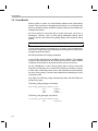
1.3 How are DSP/BIOS and RTSC Related?
Real-Time Software Components (RTSC) provides a standard for packaging
and configuring modules. DSP/BIOS is delivered as a set of RTSC packages
that provide the modules that make up DSP/BIOS.
RTSC includes a set of tools (XDCtools) and a run-time (xdc.runtime)
package that enable the development of real-time applications. DSP/BIOS
uses both the XDCtools and run-time package. This is different from earlier
releases (prior to DSP/BIOS 6.00), in which the configuration tools were
included with the kernel and all target-resident functions were part of the
kernel.
In addition the configuration tool changes, users should note the following
significant differences, compared to previous versions:
1-4
❏
Some commonly used run-time APIs are now in xdc.runtime, including
memory allocation, logging, timestamp, and system (error handling, exit,
abort, system printf, …).
❏
System start-up is now handled by the xdc.runtime package and
DSP/BIOS installs its start-up modules into the xdc.runtime package.
Developers will now need to install their initialization code into the XDC
runtime start-up, not DSP/BIOS.
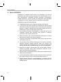
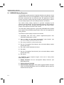
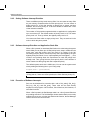
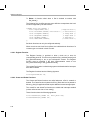
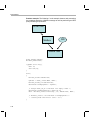
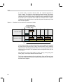
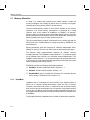
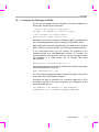
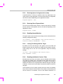
How are DSP/BIOS and RTSC Related?
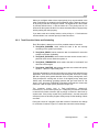
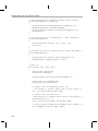
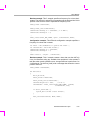
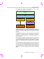
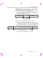
You can picture the architecture of the tools used to create applications as
shown in the following figure:
xdc.runtime
Package
DSP/BIOS
DSP/BIOS
DSP/BIOS
Packages
DSP/BIOS
Packages
Packages
Packages
Other
Other
Other
(3rd
Party)
(3rd Party)
(3rd
Party)
Packages
Packages
Packages
XDC Tools
Texas
Instruments
compilers
Microsoft
compilers
other
compilers
This book describes the DSP/BIOS packages. The XDCtools Consumer
User’s Guide describes the components with the red background (XDCtools
and the xdc.runtime package).
Before continuing with this book, you may wish familiarize yourself with the
basics
of
RTSC
by
visiting
the
RTSC-Pedia
wiki
at
http://rtsc.eclipse.org/docs-tip. This book assumes that you know the general
procedure for using XDCtools to configure objects: to create objects
statically, to set module-wide and instance-only properties. It also assumes
that you know the general procedure for including the header file of a package
and calling a function from that package.
About DSP/BIOS
1-5
DSP/BIOS Packages
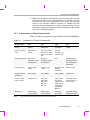
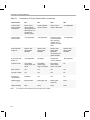
1.4 DSP/BIOS Packages
DSP/BIOS provides the following packages:
Table 1–1 Packages and Modules Provides by DSP/BIOS
1-6
Package
Description
ti.bios, ti.bios.tconf
Contains header files and configuration parameters
used by DSP/BIOS 5.x programs. See SPRAAS7.
ti.bios.conversion
Provides a command-line conversion tool for
DSP/BIOS 5.x applications. See SPRAAS7.
ti.sysbios.benchmark
Contains specifications for benchmark tests.
Provides no modules, APIs, or configuration. See
Appendix B.
ti.sysbios.family.*
Contains specifications for target/device-specific functions.
ti.sysbios.gates
Contains several implementations of the IGateProvider interface for use in various situations. These
include GateHwi, GateSwi, GateTask, GateMutex,
and GateMutexPri. See Section 3.3.
ti.sysbios.genx
Provides a command-line tool to build example applications.
ti.sysbios.hal
Contains Hwi, Timer, and Cache modules. See Section 6.2, Section 6.3, and Section 6.4.
ti.sysbios.heaps
Provides several implementations of the XDCtools
IHeap interface. These include HeapBuf (fixed-size
buffers), HeapMem (variable-sized buffers), and
HeapMultiBuf (multiple fixed-size buffers). See Chapter 5.
ti.sysbios.interfaces
Contains interfaces for modules to be implemented,
for example, on a device or platform basis.
ti.sysbios.ipc
Contains modules related to inter-process communication: Event, Mailbox, and Semaphore. See
Chapter 3.
ti.sysbios.knl
Contains modules for the DSP/BIOS kernel, including
Swi, Task, Idle, and Clock. See Chapter 2 and
Chapter 4.
ti.sysbios.utils
Contains Load module, which provides global CPU
load as well as thread-specific load.
For More Information
1.5 For More Information
You can read the following additional documents to learn more about
DSP/BIOS and XDCtools:
1.5.1
❏
XDCtools Release Notes (in XDC_INSTALL_DIR). Includes information
about software version, upgrades and compatibility, host and target
device support, validation, and known issues.
❏
DSP/BIOS Release Notes (BIOS_INSTALL_DIR/release_notes.html).
Includes information about changes in each version, known issues,
validation, and device support.
❏
DSP/BIOS Getting Started Guide (BIOS_INSTALL_DIR/docs/
Bios_Getting_Started_Guide.doc). Includes steps for installing and
validating the installation.
❏
Migrating a DSP/BIOS 5 Application to DSP/BIOS 6 (SPRAAS7A).
(BIOS_INSTALL_DIR/docs/Bios_Legacy_App_Note.pdf)
❏
RTSC-Pedia wiki: http://rtsc.eclipse.org/docs-tip
❏
Code Composer Studio Mediawiki:
http://tiexpressdsp.com/wiki/index.php?title=CCSv4
❏
CCSv4 online help contains reference information about XDCtools and
DSP/BIOS packages and their modules, APIs, XDCtools configuration,
data structures, etc. See Section 1.5.1.
Using the API Reference Help System
To open the online help for DSP/BIOS, you can choose DSP/BIOS API
Documentation from the Texas Instruments > DSP/BIOS group in the
Windows Start menu.
To open online help for XDCtools, you can choose XDCtools
Documentation from the Texas Instruments > XDCtools group in the
Windows Start menu.
You can also open help for CCSv4, DSP/BIOS, and XDCtools together from
within CCSv4.
To see the DSP/BIOS API documentation, you must have included your
DSP/BIOS installation directory path in the XDCPATH environment variable.
Please refer to the XDCtools Getting Started Guide for details on how to do
this.
About DSP/BIOS
1-7
For More Information
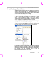
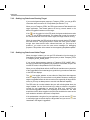
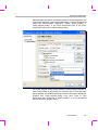
Click "+" next to a repository to expand its list of packages. Click "+" next to
a package name to see the list of modules it provides. You can further expand
the tree to see a list of the functions provided by a module. Double-click on a
package or module to see its reference information.
The DSP/BIOS API documentation is under the "sysbios" package. To view
API documentation on memory allocation, logs, timestamps, asserts, and
system, expand the "xdc.runtime" package. The "bios" package contains only
the compatibility modules for earlier versions of DSP/BIOS.
Notice the following icons in this window:
Busy displaying the requested page.
Close all page tabs.
For each topic you view, there is a tab across the top of the page area. You
can use these to quickly return to other pages you have viewed. You can also
use the arrows next to "Views" to move backward and forward in your history
of page views.
To close a page and remove its tab, click the X on the tab.
The xs option '--xp' adds the DSP/BIOS 6.0 packages to the path searched
for XDCtools packages. If you have added this directory to your XDCPATH
environment variable definition as described in the DSP/BIOS 6 Getting
Started Guide, you do not need to use the --xp command-line option.
1-8
Chapter 2
Threading Modules
This chapter describes the types of threads a DSP/BIOS program can use.
Topic
Page
2.1
DSP/BIOS Startup Sequence . . . . . . . . . . . . . . . . . . . . . . . . . . . . . . . . 2-2
2.2
Overview of Threading Modules . . . . . . . . . . . . . . . . . . . . . . . . . . . . . 2-4
2.3
Hardware Interrupts . . . . . . . . . . . . . . . . . . . . . . . . . . . . . . . . . . . . . . 2-15
2.4
Software Interrupts . . . . . . . . . . . . . . . . . . . . . . . . . . . . . . . . . . . . . . . 2-24
2.5
Tasks . . . . . . . . . . . . . . . . . . . . . . . . . . . . . . . . . . . . . . . . . . . . . . . . . . 2-43
2.6
The Idle Loop . . . . . . . . . . . . . . . . . . . . . . . . . . . . . . . . . . . . . . . . . . . . 2-61
2.7
Example Using Hwi, Swi, and Task Threads . . . . . . . . . . . . . . . . . . 2-62
2-1
DSP/BIOS Startup Sequence
2.1 DSP/BIOS Startup Sequence
The DSP/BIOS startup sequence is logically divided into two phases—those
operations that occur prior to the application's "main()" function being called
and those operations that are performed after the application's "main()"
function is invoked. Control points are provided at various places in each of
the two startup sequences for user startup functions to be inserted.
The "before main()" startup sequence is governed completely by the
XDCtools runtime package. For more information about the boot sequence
prior to main, refer to the "XDCtools Boot Sequence and Control Points"
section in the XDCtools Consumer User's Guide.
The "after main()" startup sequence is governed by DSP/BIOS and is initiated
by an explicit call to the BIOS_start() function at the end of the application's
main() function.
The XDCtools runtime startup sequence is as follows:
1) Immediately after CPU reset, perform target/device-specific CPU
initialization (beginning at c_int00).
2) Prior to cinit(), run the single user-supplied "reset function" (the
xdc.runtime.Startup module provides this hook).
3) Run cinit() to initialize C runtime environment.
4) Run the user-supplied "first functions" (the xdc.runtime.Startup module
provides this hook).
5) Run all the module initialization functions.
6) Run pinit().
7) Run the user-supplied "last functions" (the xdc.runtime.Startup module
provides this hook).
8) Run main().
The DSP/BIOS startup sequence begins at the end of main() when
BIOS_start() is called:
1) Startup Functions. Run the user-supplied "startup functions" (see
BIOS.startupFxns).
2) Enable Hardware Interrupts.
3) Enable Software Interrupts. If the system supports software interrupts
(Swis) (see BIOS.swiEnabled), then the DSP/BIOS startup sequence
enables Swis at this point.
2-2
DSP/BIOS Startup Sequence
4) Timer Startup. If the system supports Timers, then at this point all
configured timers are initialized per their user-configuration. If a timer was
configured to start "automatically", it is started here.
5) Task Startup. If the system supports Tasks (see BIOS.taskEnabled),
then task scheduling begins here. If there are no statically or dynamically
created Tasks in the system, then execution proceeds directly to the idle
loop.
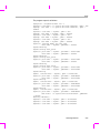
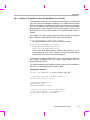
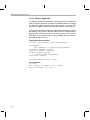
The following configuration script excerpt installs a user-supplied startup
function at every possible control point in the RTSC and DSP/BIOS startup
sequence:
/* get handle to xdc Startup module */
var Startup = xdc.useModule('xdc.runtime.Startup');
/* install "reset function" */
Startup.resetFxn = '&myReset';
/* install a "first function" */
var len = Startup.firstFxns.length
Startup.firstFxns.length++;
Startup.firstFxns[len] = '&myFirst';
/* install a "last function" */
var len = Startup.lastFxns.length
Startup.lastFxns.length++;
Startup.lastFxns[len] = '&myLast';
/* get handle to BIOS module */
var BIOS = xdc.useModule('ti.sysbios.BIOS');
/* install a BIOS startup function */
BIOS.addUserStartupFunction('&myBiosStartup');
Threading Modules
2-3
Overview of Threading Modules
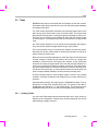
2.2 Overview of Threading Modules
Many real-time applications must perform a number of seemingly unrelated
functions at the same time, often in response to external events such as the
availability of data or the presence of a control signal. Both the functions
performed and when they are performed are important.
These functions are called threads. Different systems define threads either
narrowly or broadly. Within DSP/BIOS, the term is defined broadly to include
any independent stream of instructions executed by the processor. A thread
is a single point of control that can activate a function call or an interrupt
service routine (ISR).
DSP/BIOS enables your applications to be structured as a collection of
threads, each of which carries out a modularized function. Multithreaded
programs run on a single processor by allowing higher-priority threads to
preempt lower-priority threads and by allowing various types of interaction
between threads, including blocking, communication, and synchronization.
Real-time application programs organized in such a modular fashion—as
opposed to a single, centralized polling loop, for example—are easier to
design, implement, and maintain.
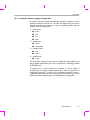
DSP/BIOS provides support for several types of program threads with
different priorities. Each thread type has different execution and preemption
characteristics. The thread types (from highest to lowest priority) are:
❏
❏
❏
❏
Hardware interrupts (Hwi), which includes Timer functions
Software interrupts (Swi), which includes Clock functions
Tasks (Task)
Background thread (Idle)
These thread types are described briefly in the following section and
discussed in more detail in the rest of this chapter.
2.2.1
Types of Threads
The four major types of threads in a DSP/BIOS program are:
❏
2-4
Hardware interrupt (Hwi) threads. Hwi threads (also called Interrupt
Service Routines or ISRs) are the threads with the highest priority in a
DSP/BIOS application. Hwi threads are used to perform time critical tasks
that are subject to hard deadlines. They are triggered in response to
external asynchronous events (interrupts) that occur in the real-time
environment. Hwi threads always run to completion but can be
preempted temporarily by Hwi threads triggered by other interrupts, if
Overview of Threading Modules
enabled. See Section 4.2, Hardware Interrupts, page 4-11, for details
about hardware interrupts. See Section 2.3, Hardware Interrupts, page 215, for details about hardware interrupts.
❏
Software interrupt (Swi) threads. Patterned after hardware interrupts
(Hwi), software interrupt threads provide additional priority levels
between Hwi threads and Task threads. Unlike Hwis, which are triggered
by hardware interrupts, Swis are triggered programmatically by calling
certain Swi module APIs. Swis handle threads subject to time constraints
that preclude them from being run as tasks, but whose deadlines are not
as severe as those of hardware ISRs. Like Hwi's, Swi's threads always
run to completion. Swis allow Hwis to defer less critical processing to a
lower-priority thread, minimizing the time the CPU spends inside an
interrupt service routine, where other Hwis can be disabled. See Section
2.4, Software Interrupts, page 2-24, for details about Swis.
❏
Task (Task) threads. Task threads have higher priority than the
background (Idle) thread and lower priority than software interrupts.
Tasks differ from software interrupts in that they can wait (block) during
execution until necessary resources are available. DSP/BIOS provides a
number of mechanisms that can be used for inter-task communication
and synchronization. These include Semaphores, Events, Message
queues, and Mailboxes. See Section 2.5, Tasks, page 2-43, for details
about tasks.
❏
Idle Loop (Idle) thread. Idle threads execute at the lowest priority in a
DSP/BIOS application and are executed one after another in a
continuous loop (the Idle Loop). After main returns, a DSP/BIOS
application calls the startup routine for each DSP/BIOS module and then
falls into the Idle Loop. Each thread must wait for all others to finish
executing before it is called again. The Idle Loop runs continuously
except when it is preempted by higher-priority threads. Only functions
that do not have hard deadlines should be executed in the Idle Loop. See
Section 2.6, The Idle Loop, page 2-61, for details about the background
thread.
Another type of thread, a Clock thread, is run within the context of a Swi
thread that is triggered by a Hwi thread invoked by a repetitive timer
peripheral interrupt. See Section 4.2 for details.
Threading Modules
2-5
Overview of Threading Modules
2.2.2
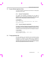
Choosing Which Types of Threads to Use
The type and priority level you choose for each thread in an application
program has an impact on whether the threads are scheduled on time and
executed correctly. DSP/BIOS static configuration makes it easy to change a
thread from one type to another.
A program can use multiple types of threads. Here are some rules for
deciding which type of object to use for each thread to be performed by a
program.
2-6
❏
Swi or Task versus Hwi. Perform only critical processing within hardware
interrupt service routines. Hwis should be considered for processing
hardware interrupts (IRQs) with deadlines down to the 5-microsecond
range, especially when data may be overwritten if the deadline is not met.
Swis or Tasks should be considered for events with longer deadlines—
around 100 microseconds or more. Your Hwi functions should post Swis
or tasks to perform lower-priority processing. Using lower-priority threads
minimizes the length of time interrupts are disabled (interrupt latency),
allowing other hardware interrupts to occur.
❏
Swi versus Task. Use Swis if functions have relatively simple
interdependencies and data sharing requirements. Use tasks if the
requirements are more complex. While higher-priority threads can
preempt lower priority threads, only tasks can wait for another event, such
as resource availability. Tasks also have more options than Swis when
using shared data. All input needed by a Swi’s function should be ready
when the program posts the Swi. The Swi object’s trigger structure
provides a way to determine when resources are available. Swis are more
memory-efficient because they all run from a single stack.
❏
Idle. Create Idle threads to perform noncritical housekeeping tasks when
no other processing is necessary. Idle threads typically have no hard
deadlines. Instead, they run when the system has unused processor time.
You may use Idle threads to reduce power needs when other processing
is not being performed. In this case, you should not depend upon
housekeeping tasks to occur during power reduction times.
❏
Clock. Use Clock functions when you want a function to run at a rate
based on a multiple of the interrupt rate of the peripheral that is driving the
Clock tick. Clock functions can be configured to execute either periodically
or just once. These functions run as Swi functions.
❏
Clock versus Swi. All Clock functions run at the same Swi priority, so one
Clock function cannot preempt another. However, Clock functions can
post lower-priority Swi threads for lengthy processing. This ensures that
the Clock Swi can preempt those functions when the next system tick
occurs and when the Clock Swi is posted again.
Overview of Threading Modules
❏
2.2.3
Timer. Timer threads are run within the context of a Hwi thread. As such,
they inherit the priority of the corresponding Timer interrupt. They are
invoked at the rate of the programmed Timer period. Timer threads
should do the absolute minimum necessary to complete the task
required. If more processing time is required, consider posting a Swi to
do the work or posting a Semaphore for later processing by a task so that
CPU time is efficiently managed.
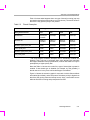
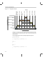
A Comparison of Thread Characteristics
Table 2-1 provides a comparison of the thread types supported by DSP/BIOS.
Table 2-1.
Comparison of Thread Characteristics
Characteristic
Hwi
Swi
Task
Idle
Priority
Highest
2nd highest
2nd lowest
Lowest
Number of priority
levels
family/devicespecific
Up to 32. Periodic
functions run at the
priority of the Clock
Swi.
Up to 32
(including 1 for
the Idle Loop)
1
Can yield and pend
No, runs to
completion except
for preemption
No, runs to
completion except
for preemption
Yes
Should not pend.
Pending would disable all registered
Idle threads.
Execution states
Inactive, ready,
running
Inactive, ready,
running
Ready, running,
blocked,
terminated
Ready, running
Thread scheduler
disabled by
Hwi_disable()
Swi_disable()
Task_disable()
Program exit
Posted or made
ready to run by
Interrupt occurs
Swi_post(),
Swi_andn(),
Swi_dec(),
Swi_inc(),
Swi_or()
Task_create()
and various
task synchronization mechanisms (Event,
Semaphore,
Mailbox)
main() exits and no
other thread is currently running
Stack used
System stack
(1 per program)
System stack
(1 per program)
Task stack
(1 per task)
Task stack used by
default (see Note 1)
Notes:
1) If you disable the Task Manager, Idle threads use the system stack.
Threading Modules
2-7
Overview of Threading Modules
Table 2.1.
Comparison of Thread Characteristics (continued)
Characteristic
Hwi
Swi
Task
Idle
Context saved
when preempts
other thread
Entire context
minus saved-bycallee registers (as
defined by the TI C
compiler) are
saved to system.
Certain registers
saved to system.
Entire context
saved to task stack
--Not applicable--
Context saved
when blocked
--Not applicable--
--Not applicable--
Saves the savedby-callee registers
(see optimizing
compiler user’s
guide for your platform).
--Not applicable--
Share data with
thread via
Streams, lists,
pipes, global
variables
Streams, lists,
pipes, global
variables
Streams, lists,
pipes, gates,
mailboxes,
message queues,
global variables
Streams, lists,
pipes, global
variables
Synchronize with
thread via
--Not applicable--
Swi trigger
Semaphores,
events, mailboxes
-Not applicable--
Function hooks
Yes: register,
create, begin, end,
delete
Yes:register,
create, ready,
begin, end, delete
Yes: register,
create, ready,
switch, exit, delete
No
Static creation
Yes
Yes
Yes
Yes
Dynamic creation
Yes
Yes
Yes
No
Dynamically
change priority
See Note 1
Yes
Yes
No
Implicit logging
Interrupt event
Post, begin, end
Switch, yield,
ready, exit
None
Implicit statistics
None
None
None
None
Notes:
2-8
1) Some devices allow hardware interrupt priorities to by modified.
Overview of Threading Modules
2.2.4
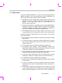
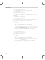
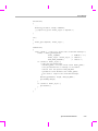
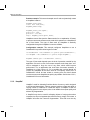
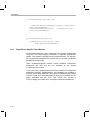
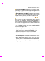
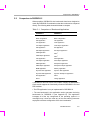
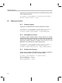
Thread Priorities
Within DSP/BIOS, hardware interrupts have the highest priority. The priorities
among the set of Hwi objects are not maintained implicitly by DSP/BIOS. The
Hwi priority only applies to the order in which multiple interrupts that are ready
on a given CPU cycle are serviced by the CPU. Hardware interrupts are
preempted by another interrupt unless interrupts are globally disabled or
when specific interrupts are individually disabled.
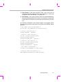
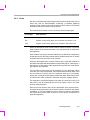
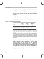
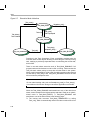
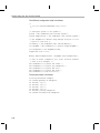
Thread Priorities
Hardware
Interrupts
(Hwi)
Priority
Figure 2-1.
Timer
Functions
Software
Interrupts
Clock
Functions
(Swi)
up to 32 levels
Tasks
up to 32 levels
Background thread
(Idle)
Swis have lower priority than Hwis. There are up to 32 priority levels available
for Swis (16 by default). Swis can be preempted by a higher-priority Swi or
any Hwi. Swis cannot block.
Tasks have lower priority than Swis. There are up to 32 task priority levels (16
by default). Tasks can be preempted by any higher-priority thread. Tasks can
block while waiting for resource availability and lower-priority threads.
The background Idle Loop is the thread with the lowest priority of all. It runs
in a loop when the CPU is not busy running another thread. When tasks are
enabled, the Idle Loop is implemented as the only task running at priority 0.
When tasks are disabled, the Idle Loop is fallen into after the application's
"main()" function is called.
Threading Modules
2-9
Overview of Threading Modules
2.2.5
Yielding and Preemption
The DSP/BIOS thread schedulers run the highest-priority thread that is ready
to run except in the following cases:
❏
The thread that is running disables some or all hardware interrupts
temporarily with Hwi_disable() or Hwi_disableInterrupt(), preventing
hardware ISRs from running.
❏
The thread that is running disables Swis temporarily with Swi_disable().
This prevents any higher-priority Swi from preempting the current thread.
It does not prevent Hwis from preempting the current thread.
❏
The thread that is running disables task scheduling temporarily with
Task_disable(). This prevents any higher-priority task from preempting
the current task. It does not prevent Hwis and Swis from preempting the
current task.
Both Hwis and Swis can interact with the DSP/BIOS task scheduler. When a
task is blocked, it is often because the task is pending on a semaphore which
is unavailable. Semaphores can be posted from Hwis and Swis as well as
from other tasks. If a Hwi or Swi posts a semaphore to unblock a pending
task, the processor switches to that task if that task has a higher priority than
the currently running task (after the Hwi or Swi completes).
When running either a Hwi or Swi, DSP/BIOS uses a dedicated system
interrupt stack, called the system stack (sometimes called the ISR stack).
Each task uses its own private stack. Therefore, if there are no Tasks in the
system, all threads share the same system stack. For performance reasons,
sometimes it is advantageous to place the system stack in precious fast
memory.
2-10
Overview of Threading Modules
Table 2-2 shows what happens when one type of thread is running (top row)
and another thread becomes ready to run (left column). The action shown is
that of the newly posted (ready to run) thread.
Table 2-2.
Thread Preemption
Running Thread
Newly Posted Thread
Hwi
Swi
Task
Idle
Enabled Hwi
Preempts if
enabled*
Preempts
Preempts
Preempts
Disabled Hwi
Waits for
reenable
Waits for
reenable
Waits for
reenable
Waits for
reenable
Enabled, higher-priority Swi
Waits
Preempts
Preempts
Preempts
Lower-priority Swi
Waits
Waits
Preempts
Preempts
Enabled, higher-priority Task
Waits
Waits
Preempts
Preempts
Low-priority Task
Waits
Waits
Waits
Preempts
* On some targets, hardware interrupts can be individually enabled and
disabled. This is not true on all targets. Also, some targets have controllers
that support hardware interrupt prioritization, in which case a Hwi can only be
preempted by a higher-priority Hwi.
Note that Table 2-2 shows the results if the type of thread that is posted is
enabled. If that thread type is disabled (for example, by Task_disable), a
thread cannot run in any case until its thread type is reenabled.
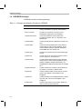
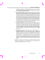
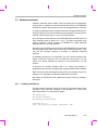
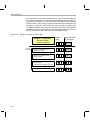
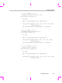
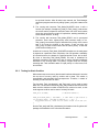
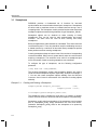
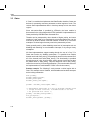
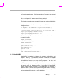
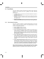
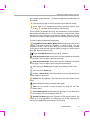
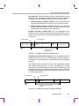
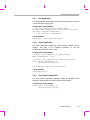
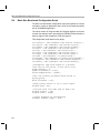
Figure 2-2 shows the execution graph for a scenario in which Swis and Hwis
are enabled (the default), and a Hwi posts a Swi whose priority is higher than
that of the Swi running when the interrupt occurs. Also, a second Hwi occurs
while the first ISR is running and preempts the first ISR.
Threading Modules
2-11
Overview of Threading Modules
Figure 2-2.
Preemption Scenario
Swi B finishes
Swi A finishes
Hwi 2 finishes
Hwi 1 finishes
Hwi 1 occurs
Hwi 2 posts
Swi A
Hwi 2 occurs
Background
posts Swi B
Events
Thread Priority
Increasing Priority
Hardware interrupt 1
(Hwi 1)
Hardware interrupt 2
(Hwi 2)
preempted
Software interrupt A
(Swi A)
Swi A ready
Software interrupt B
(Swi B)
Swi B preempted
Background
(Idle)
background preempted
Time
In Figure 2-2, the low-priority Swi is asynchronously preempted by the Hwis.
The first Hwi posts a higher-priority Swi, which is executed after both Hwis
finish executing.
Here is sample pseudo-code for the example depicted in Figure 2-2:
backgroundThread()
{
Swi_post(Swi_B) /* priority = 5 */
}
Hwi_1 ()
{
. . .
}
Hwi_2 ()
{
Swi_post(Swi_A) /* priority = 7 */
}
2-12
Overview of Threading Modules
2.2.6
Hooks
Hwi, Swi, and Task threads optionally provide points in a thread's life cycle to
insert user code for instrumentation, monitoring, or statistics gathering
purposes. Each of these code points is called a "hook" and the user function
provided for the hook is called a "hook function".
The following hook functions can be set for the various thread types:
Thread Type
Hook Functions
Hwi
Register, Create, Begin, End, and Delete. See Section 2.3.2.
Swi
Register, Create, Ready, Begin, End, and Delete. See Section 2.4.8.
Task
Register, Create, Ready, Switch, Exit, and Delete. See Section 2.5.4.
Hooks are declared as a set of hook functions called "hook sets". You do not
need to define all hook functions within a set, only those that are required by
the application.
Hook functions can only be declared statically (in an XDCtools configuration)
so that they may be efficiently invoked when provided and result in no runtime
overhead when a hook function is not provided.
Except for the Register hook, all hook functions are invoked with a handle to
the object associated with that thread as its argument (that is, a Hwi object, a
Swi object, or a Task object). Other arguments are provided for some threadtype-specific hook functions.
You can define as many hook sets as necessary for your application. When
more than one hook set is defined, the individual hook functions within each
set are invoked in hook ID order for a particular hook type. For example,
during Task_create() the order that the Create hook within each Task hook set
is invoked is the order in which the Task hook sets were originally defined.
The argument to a thread's Register hook (which is invoked only once) is an
index (the "hook ID") indicating the hook set's relative order in the hook
function calling sequence.
Each set of hook functions has a unique associated "hook context pointer".
This general-purpose pointer can be used by itself to hold hook set specific
information, or it can be initialized to point to a block of memory allocated by
the Create hook function within a hook set if more space is required for a
particular application.
Threading Modules
2-13
Overview of Threading Modules
An individual hook function obtains the value of its associated context pointer
through
thread-type-specific
APIs—Hwi_getHookContext(),
Swi_getHookContext(), and Task_getHookContext(). Corresponding APIs for
initializing the context pointers are also provided—Hwi_setHookContext(),
Swi_setHookContext(), and Task_setHookContext(). Each of these APIs take
the hook ID as an argument.
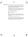
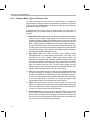
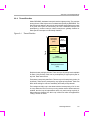
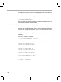
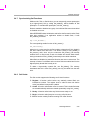
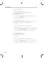
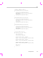
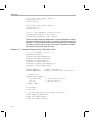
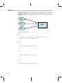
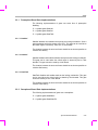
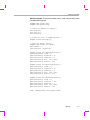
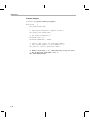
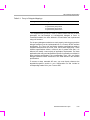
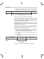
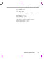
The following diagram shows an application with three Hwi hook sets:
Hwi Hook Set [0]
registerHookFunc0()
createHookFunc0()
beginHookFunc0()
endHookFunc0()
deleteHookFunc0()
Hwi Hook Set [1]
registerHookFunc1()
createHookFunc1()
beginHookFunc1()
endHookFunc1()
deleteHookFunc1()
Hwi Hook Set [2]
registerHookFunc2()
createHookFunc2()
beginHookFunc2()
endHookFunc2()
deleteHookFunc2()
Hwi_getHookContext(1)
Hwi_getHookContext(0)
Hwi_getHookContext(2)
hookContextPtr[0]
hookContextPtr[1]
hookContextPtr[2]
The hook context pointers are accessed using Hwi_getHookContext() using
the index provided to the three Register hook functions.
Just prior to invoking your ISR functions, the Begin Hook functions are
invoked in the following order:
1) beginHookFunc0();
2) beginHookFunc1();
3) beginHookFunc2();
Likewise, upon return from your ISR functions the End Hook functions are
invoked in the following order:
1) endHookFunc0();
2) endHookFunc1();
3) endHookFunc2();
2-14
Hardware Interrupts
2.3 Hardware Interrupts
Hardware interrupts (Hwis) handle critical processing that the application
must perform in response to external asynchronous events. The DSP/BIOS
target/device specific Hwi modules are used to manage hardware interrupts.
In a typical embedded system, hardware interrupts are triggered either by ondevice peripherals or by devices external to the processor. In both cases, the
interrupt causes the processor to vector to the ISR address.
Any interrupt processing that may invoke DSP/BIOS APIs that affect Swi and
Task scheduling must be written in C or C++. The HWI_enter()/HWI_exit()
macros provided in earlier versions of DSP/BIOS for calling assembly
language ISRs are no longer provided.
Assembly language ISRs that do not interact with DSP/BIOS can be specified
with Hwi_plug(). Such ISRs must do their own context preservation. They
may use the "interrupt" keyword, C functions, or assembly language
functions.
All hardware interrupts run to completion. If a Hwi is posted multiple times
before its ISR has a chance to run, the ISR runs only one time. For this
reason, you should minimize the amount of code performed by a Hwi
function.
If interrupts are globally enabled—that is, by calling Hwi_enable()—a
hardware interrupt can be preempted by any interrupt that has been enabled.
Hwis must not use the Chip Support Library (CSL) for the target. Instead, see
Chapter 6 for a description of Hardware Abstraction Layer APIs.
Associating an ISR function with a particular interrupt is done by creating a
Hwi object.
2.3.1
Creating Hwi Objects
The Hwi module maintains a table of pointers to Hwi objects that contain
information about each Hwi managed by the dispatcher. To create a Hwi
object dynamically, use a call with this syntax:
Hwi_Handle hwi0;
Hwi_Params hwiParams;
Hwi_Params_init(&hwiParams);
hwiParams.arg = 5;
hwi0 = Hwi_create(id, hwiFunc, &hwiParams, &eb);
Threading Modules
2-15
Hardware Interrupts
Here, hwi0 is a handle to the created Hwi object, id is the interrupt number
being defined, hwiFunc is the name of the function associated with the Hwi,
and hwiParams is a structure that contains Hwi instance parameters
(enable/restore masks, the Hwi function argument, etc). Here,
hwiParams.arg is set to 5. If NULL is passed instead of a pointer to an actual
Hwi_Params struct, a default set of parameters is used. The "eb" is an error
block that you can use to handle errors that may occur during Hwi object
creation.
The corresponding static configuration Hwi object creation syntax is:
var Hwi = xdc.useModule('ti.sysbios.hal.Hwi');
var hwiParams = new Hwi.Params;
hwiParams.arg = 5;
Program.global.hwi0 = Hwi.create(id, '&hwiFunc', hwiParams);
Here, the "hwiParams = new Hwi.Params" statement does the equivalent of
creating and initializing the hwiParams structure with default values. In the
static configuration world, no Error Block (eb) is required for the "create"
function. The "Program.global.hwi0" name becomes a a runtime-accessible
handle (symbol name = "hwi0") to the statically-created Hwi object.
2.3.2
Hwi Hooks
The Hwi module supports the following set of Hook functions:
2-16
❏
Register. A function called before any statically created Hwis are
initialized at runtime. The register hook is called at boot time before
main() and before interrupts are enabled.
❏
Create. A function called when a Hwi is created. This includes Hwis that
are created statically and those created dynamically using Hwi_create().
❏
Begin. A function called just prior to running a Hwi ISR function.
❏
End. A function called just after a Hwi ISR function finishes.
❏
Delete. A function called when a Hwi is deleted at runtime with
Hwi_delete().
Hardware Interrupts
The following HookSet structure type definition encapsulates the hook
functions supported by the Hwi module:
typedef struct Hwi_HookSet {
Void (*registerFxn)(Int);
/* Register Hook */
Void (*createFxn)(Handle, Error.Block *); /* Create Hook */
Void (*beginFxn)(Handle);
/* Begin Hook */
Void (*endFxn)(Handle);
/* End Hook */
Void (*deleteFxn)(Handle);
/* Delete Hook */
};
Hwi Hook functions can only be configured statically.
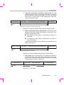
2.3.2.1 Register Function
The register function is provided to allow a hook set to store its corresponding
hook ID. This ID can be passed to Hwi_setHookContext() and
Hwi_getHookContext() to set or get hook-specific context. The Register
function must be specified if the hook implementation needs to use
Hwi_setHookContext() or Hwi_getHookContext().
The registerFxn hook function is called during system initialization before
interrupts have been enabled.
The Register function has the following signature:
Void registerFxn(Int id);
2.3.2.2 Create and Delete Functions
The Create and Delete functions are called whenever a Hwi is created or
deleted. The Create function is passed an Error_Block that is to be passed to
Memory_alloc() for applications that require additional context storage space.
The createFxn and deleteFxn functions are called with interrupts enabled
(unless called at boot time or from main()).
These functions have the following signatures:
Void createFxn(Hwi_Handle hwi, Error_Block *eb);
Void deleteFxn(Hwi_Handle hwi);
2.3.2.3 Begin and End Functions
The Begin and End hook functions are called with interrupts globally disabled,
therefore any hook processing function contributes to overall system interrupt
response latency. In order to minimize this impact, carefully consider the
processing time spent in a Hwi beginFxn or endFxn hook function.
Threading Modules
2-17
Hardware Interrupts
The beginFxn is invoked just prior to calling the ISR function. The endFxn is
invoked immediately after the return from the ISR function.
These functions have the following signatures:
Void beginFxn(Hwi_Handle hwi);
Void endFxn(Hwi_Handle hwi);
When more than one Hook Set is defined, the individual hook functions of a
common type are invoked in hook ID order.
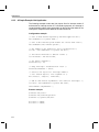
2.3.2.4 Hwi Hooks Example
The following example application uses two Hwi hook sets. The Hwi
associated with a statically-created Timer is used to exercise the Hwi hook
functions. This example demonstrates how to read and write the Hook
Context Pointer associated with each hook set.
The XDCtools configuration script and program output are shown after the C
code listing.
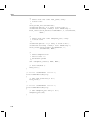
This is the C code for the example:
/* ======== HwiHookExample.c ========
* This example demonstrates basic Hwi hook usage. */
#include
#include
#include
#include
<xdc/std.h>
<xdc/runtime/Error.h>
<xdc/runtime/System.h>
<xdc/runtime/Timestamp.h>
#include
#include
#include
#include
<ti/sysbios/BIOS.h>
<ti/sysbios/knl/Task.h>
<ti/sysbios/hal/Timer.h>
<ti/sysbios/hal/Hwi.h>
extern Timer_Handle myTimer;
volatile Bool myEnd2Flag = FALSE;
Int myHookSetId1, myHookSetId2;
/* HookSet 1 functions */
2-18
Hardware Interrupts
/* ======== myRegister1 ========
* invoked during Hwi module startup before main()
* for each HookSet */
Void myRegister1(Int hookSetId)
{
System_printf("myRegister1: assigned hookSet Id = %d\n",
hookSetId);
myHookSetId1 = hookSetId;
}
/* ======== myCreate1 ========
* invoked during Hwi module startup before main()
* for statically created Hwis */
Void myCreate1(Hwi_Handle hwi, Error_Block *eb)
{
Ptr pEnv;
pEnv = Hwi_getHookContext(hwi, myHookSetId1);
/* pEnv should be 0 at this point. If not, there's a bug. */
System_printf("myCreate1: pEnv = 0x%x, time = %d\n", pEnv,
Timestamp_get32());
Hwi_setHookContext(hwi, myHookSetId1, (Ptr)0xdead1);
}
/* ======== myBegin1 ========
* invoked before Timer Hwi func */
Void myBegin1(Hwi_Handle hwi)
{
Ptr pEnv;
pEnv = Hwi_getHookContext(hwi, myHookSetId1);
System_printf("myBegin1: pEnv = 0x%x, time = %d\n", pEnv,
Timestamp_get32());
Hwi_setHookContext(hwi, myHookSetId1, (Ptr)0xbeef1);
}
Threading Modules
2-19
Hardware Interrupts
/* ======== myEnd1 ========
* invoked after Timer Hwi func */
Void myEnd1(Hwi_Handle hwi)
{
Ptr pEnv;
pEnv = Hwi_getHookContext(hwi, myHookSetId1);
System_printf("myEnd1: pEnv = 0x%x, time = %d\n", pEnv,
Timestamp_get32());
Hwi_setHookContext(hwi, myHookSetId1, (Ptr)0xc0de1);
}
/* HookSet 2 functions */
/* ======== myRegister2 ========
* invoked during Hwi module startup before main
* for each HookSet */
Void myRegister2(Int hookSetId)
{
System_printf("myRegister2: assigned hookSet Id = %d\n",
hookSetId);
myHookSetId2 = hookSetId;
}
/* ======== myCreate2 ========
* invoked during Hwi module startup before main
* for statically created Hwis */
Void myCreate2(Hwi_Handle hwi, Error_Block *eb)
{
Ptr pEnv;
pEnv = Hwi_getHookContext(hwi, myHookSetId2);
/* pEnv should be 0 at this point. If not, there's a bug. */
System_printf("myCreate2: pEnv = 0x%x, time = %d\n", pEnv,
Timestamp_get32());
Hwi_setHookContext(hwi, myHookSetId2, (Ptr)0xdead2);
}
/* ======== myBegin2 ========
* invoked before Timer Hwi func */
Void myBegin2(Hwi_Handle hwi)
{
Ptr pEnv;
pEnv = Hwi_getHookContext(hwi, myHookSetId2);
System_printf("myBegin2: pEnv = 0x%x, time = %d\n", pEnv,
Timestamp_get32());
Hwi_setHookContext(hwi, myHookSetId2, (Ptr)0xbeef2);
}
2-20
Hardware Interrupts
/* ======== myEnd2 ========
* invoked after Timer Hwi func */
Void myEnd2(Hwi_Handle hwi)
{
Ptr pEnv;
pEnv = Hwi_getHookContext(hwi, myHookSetId2);
System_printf("myEnd2: pEnv = 0x%x, time = %d\n", pEnv,
Timestamp_get32());
Hwi_setHookContext(hwi, myHookSetId2, (Ptr)0xc0de2);
myEnd2Flag = TRUE;
}
/* ======== myTimerFunc ========
* Timer interrupt handler */
Void myTimerFunc(UArg arg)
{
System_printf("Entering myTimerHwi\n");
}
/* ======== myTaskFunc ======== */
Void myTaskFunc(UArg arg0, UArg arg1)
{
System_printf("Entering myTask.\n");
Timer_start(myTimer);
/* wait for timer interrupt and myEnd2 to complete */
while (!myEnd2Flag) {
;
}
System_printf("myTask exiting ...\n");
}
/* ======== myIdleFunc ======== */
Void myIdleFunc()
{
System_printf("Entering myIdleFunc().\n");
System_exit(0);
}
Threading Modules
2-21
Hardware Interrupts
/* ======== main ======== */
Int main(Int argc, Char* argv[])
{
System_printf("Starting HwiHookExample...\n");
BIOS_start();
return (0);
}
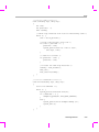
This is the XDCtools configuration script for the example:
/* pull in Timestamp to print time in hook functions */
xdc.useModule('xdc.runtime.Timestamp');
/* Disable Clock so that ours is the only Timer allocated */
var BIOS = xdc.useModule('ti.sysbios.BIOS');
BIOS.clockEnabled = false;
var Idle = xdc.useModule('ti.sysbios.knl.Idle');
Idle.addFunc('&myIdleFunc');
/* Create myTask with default task params */
var Task = xdc.useModule('ti.sysbios.knl.Task');
var taskParams = new Task.Params();
Program.global.myTask = Task.create('&myTaskFunc', taskParams);
/* Create myTimer as source of Hwi */
var Timer = xdc.useModule('ti.sysbios.hal.Timer');
var timerParams = new Timer.Params();
timerParams.startMode = Timer.StartMode_USER;
timerParams.runMode = Timer.RunMode_ONESHOT;
timerParams.period = 1000; // 1ms
Program.global.myTimer = Timer.create(Timer.ANY,
"&myTimerFunc", timerParams);
2-22
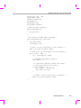
Hardware Interrupts
/* Define and add two Hwi HookSets
* Notice, no deleteFxn is provided.
*/
var Hwi = xdc.useModule('ti.sysbios.hal.Hwi');
/* Hook Set 1 */
Hwi.addHookSet({
registerFxn: '&myRegister1',
createFxn: '&myCreate1',
beginFxn: '&myBegin1',
endFxn: '&myEnd1',
});
/* Hook Set 2 */
Hwi.addHookSet({
registerFxn: '&myRegister2',
createFxn: '&myCreate2',
beginFxn: '&myBegin2',
endFxn: '&myEnd2',
});
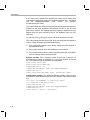
The program output is as follows:
myRegister1: assigned hookSet Id = 0
myRegister2: assigned hookSet Id = 1
myCreate1: pEnv = 0x0, time = 0
myCreate2: pEnv = 0x0, time = 0
Starting HwiHookExample...
Entering myTask.
myBegin1: pEnv = 0xdead1, time = 75415
myBegin2: pEnv = 0xdead2, time = 75834
Entering myTimerHwi
myEnd1: pEnv = 0xbeef1, time = 76427
myEnd2: pEnv = 0xbeef2, time = 76830
myTask exiting ...
Entering myIdleFunc().
Threading Modules
2-23
Software Interrupts
2.4 Software Interrupts
Software interrupts are patterned after hardware ISRs. The Swi module in
DSP/BIOS provides a software interrupt capability. Software interrupts are
triggered programmatically, through a call to a DSP/BIOS API such as
Swi_post(). Software interrupts have priorities that are higher than tasks but
lower than hardware interrupts.
Note: The Swi module should not be confused with the SWI instruction that
exists on many processors. The DSP/BIOS Swi module is independent
from any target/device-specific software interrupt features.
Swi threads are suitable for handling application tasks that occur at slower
rates or are subject to less severe real-time deadlines than those of Hwis.
The DSP/BIOS APIs that can trigger or post a Swi are:
❏
❏
❏
❏
❏
Swi_andn()
Swi_dec()
Swi_inc()
Swi_or()
Swi_post()
The Swi Manager controls the execution of all Swi functions. When the
application calls one of the APIs above, the Swi Manager schedules the
function corresponding to the specified Swi for execution. To handle Swi
functions, the Swi Manager uses Swi objects.
If a Swi is posted, it runs only after all pending Hwis have run. A Swi function
in progress can be preempted at any time by a Hwi; the Hwi completes before
the Swi function resumes. On the other hand, Swi functions always preempt
tasks. All pending Swis run before even the highest priority task is allowed to
run. In effect, a Swi function is like a task with a priority higher than all ordinary
tasks.
Note:
Two things to remember about Swi functions are:
A Swi function runs to completion unless it is interrupted by a Hwi or
preempted by a higher-priority Swi.
Any Hwi ISR that triggers or posts a Swi must have been invoked by the
Hwi dispatcher.
2-24
Software Interrupts
2.4.1
Creating Swi Objects
As with many other DSP/BIOS objects, you can create Swi objects either
dynamically—with a call to Swi_create()—or statically in the configuration.
Swis you create dynamically can also be deleted during program execution.
To add a new Swi to the configuration, create a new Swi object in the
configuration script. Set the function property for each Swi to run a function
when the object is triggered by the application. You can also configure up to
two arguments to be passed to each Swi function.
As with all modules with instances, you can determine from which memory
segment Swi objects are allocated. Swi objects are accessed by the Swi
Manager when Swis are posted and scheduled for execution.
For complete reference information on the Swi API, configuration, and
objects, see the Swi module in the "ti.sysbios.knl" package documentation in
the online documentation. (For information on running online help, see
Section 1.5.1, Using the API Reference Help System, page 1-7.)
To create a Swi object dynamically, use a call with this syntax:
Swi_Handle swi0;
Swi_Params swiParams;
Swi_Params_init(swiParams);
swi0 = Swi_create(swiFunc, &swiParams, &eb);
Here, swi0 is a handle to the created Swi object, swiFunc is the name of the
function associated with the Swi, and swiParams is a structure of type
Swi_Params that contains the Swi instance parameters (priority, arg0, arg1,
etc). If NULL is passed instead of a pointer to an actual Swi_Params struct,
a default set of parameters is used. "eb" is an error block you can use to
handle errors that may occur during Swi object creation.
Note:
Swi_create() can only be called from the task level, not from a Hwi or
another Swi.
To create a Swi object in an XDCtools configuration file, use statements like
these:
var Swi = xdc.useModule('ti.sysbios.knl.Swi');
var swiParams = new Swi.Params();
program.global.swi0 = Swi.create(swiParams);
Threading Modules
2-25
Software Interrupts
2.4.2
Setting Software Interrupt Priorities
There are different priority levels among Swis. You can create as many Swis
as your memory constraints allow for each priority level. You can choose a
higher priority for a Swi that handles a thread with a shorter real-time
deadline, and a lower priority for a Swi that handles a thread with a less
critical execution deadline.
The number of Swi priorities supported within an application is configurable
up to a maximum 32. The default number of priority levels is 16. The lowest
priority level is 0. Thus, by default, the highest priority level is 15.
You cannot sort Swis within a single priority level. They are serviced in the
order in which they were posted.
2.4.3
Software Interrupt Priorities and Application Stack Size
When a Swi is posted, its associated Swi function is invoked using the system
stack. While you can have up to 32 Swi priority levels, keep in mind that in the
worst case, each Swi priority level can result in a nesting of the Swi
scheduling function (that is, the lowest priority Swi is preempted by the next
highest priority Swi, which, in turn, is preempted by the next highest, …). This
results in an increasing stack size requirement for each Swi priority level
actually used. Thus, giving Swis the same priority level is more efficient in
terms of stack size than giving each Swi a separate priority.
The default system stack size is 4096 bytes. You can set the system stack
size by adding the following line to your config script:
Program.stack = yourStackSize;
Note: The Clock module creates and uses a Swi with the maximum Swi
priority (that is, if there are 16 Swi priorities, the Clock Swi has priority 15).
2.4.4
Execution of Software Interrupts
Swis can be scheduled for execution with a call to Swi_andn(), Swi_dec(),
Swi_inc(), Swi_or(), and Swi_post(). These calls can be used virtually
anywhere in the program—Hwi functions, Clock functions, Idle functions, or
other Swi functions.
When a Swi is posted, the Swi Manager adds it to a list of posted Swis that
are pending execution. The Swi Manager checks whether Swis are currently
enabled. If they are not, as is the case inside a Hwi function, the Swi Manager
returns control to the current thread.
2-26
Software Interrupts
If Swis are enabled, the Swi Manager checks the priority of the posted Swi
object against the priority of the thread that is currently running. If the thread
currently running is the background Idle Loop or a lower priority Swi, the Swi
Manager removes the Swi from the list of posted Swi objects and switches
the CPU control from the current thread to start execution of the posted Swi
function.
If the thread currently running is a Swi of the same or higher priority, the Swi
Manager returns control to the current thread, and the posted Swi function
runs after all other Swis of higher priority or the same priority that were
previously posted finish execution.
There are two important things to remember about Swi:
❏
When a Swi starts executing it must run to completion without blocking.
❏
When called from within a Hwi, the code sequence calling any Swi
function that can trigger or post a Swi must be invoked by the Hwi
dispatcher.
Swi functions can be preempted by threads of higher priority (such as a Hwi
or a Swi of higher priority). However, Swi functions cannot block. You cannot
suspend a Swi while it waits for something—like a device—to be ready.
If a Swi is posted multiple times before the Swi Manager has removed it from
the posted Swi list, its Swi function executes only once, much like a Hwi is
executed only once if the Hwi is triggered multiple times before the CPU
clears the corresponding interrupt flag bit in the interrupt flag register. (See
Section 2.4.5, Using a Swi Object’s Trigger Variable, page 2-27, for more
information on how to handle Swis that are posted multiple times before they
are scheduled for execution.)
Applications should not make any assumptions about the order in which Swi
functions of equal priority are called. However, a Swi function can safely post
itself (or be posted by another interrupt). If more than one is pending, all Swi
functions are called before any tasks run.
2.4.5
Using a Swi Object’s Trigger Variable
Each Swi object has an associated 32-bit trigger variable for C6x targets and
a 16-bit trigger variable for C5x targets. This is used either to determine
whether to post the Swi or to provide values that can be evaluated within the
Swi function.
Swi_post(), Swi_or(), and Swi_inc() post a Swi object unconditionally:
❏
Swi_post() does not modify the value of the Swi object trigger when it is
used to post a Swi.
Threading Modules
2-27
Software Interrupts
❏
Swi_or() sets the bits in the trigger determined by a mask that is passed
as a parameter, and then posts the Swi.
❏
Swi_inc() increases the Swi's trigger value by one before posting the Swi
object.
Swi_andn() and Swi_dec() post a Swi object only if the value of its trigger
becomes 0:
❏
Swi_andn() clears the bits in the trigger determined by a mask passed as
a parameter.
❏
Swi_dec() decreases the value of the trigger by one.
Table 2-3 summarizes the differences between these functions.
Table 2-3.
Swi Object Function Differences
Action
Treats
Trigger as
Bitmask
Treats
Trigger as
Counter
Does not
Modify
Trigger
Always post
Swi_or()
Swi_inc()
Swi_post()
Post if it becomes zero
Swi_andn()
Swi_dec()
—
The Swi trigger allows you to have tighter control over the conditions that
should cause a Swi function to be posted, or the number of times the Swi
function should be executed once the Swi is posted and scheduled for
execution.
To access the value of its trigger, a Swi function can call Swi_getTrigger().
Swi_getTrigger() can be called only from the Swi object’s function. The value
returned by Swi_getTrigger() is the value of the trigger before the Swi object
was removed from the posted Swi queue and the Swi function was scheduled
for execution.
When the Swi Manager removes a pending Swi object from the posted
object’s queue, its trigger is reset to its initial value. The initial value of the
trigger should be set in the application’s configuration script. If while the Swi
function is executing, the Swi is posted again, its trigger is updated
accordingly. However, this does not affect the value returned by
Swi_getTrigger() while the Swi function executes. That is, the trigger value
that Swi_getTrigger() returns is the latched trigger value when the Swi was
removed from the list of pending Swis. The Swi's trigger however, is
immediately reset after the Swi is removed from the list of pending Swis and
scheduled for execution. This gives the application the ability to keep
updating the value of the Swi trigger if a new posting occurs, even if the Swi
function has not finished its execution.
2-28
Software Interrupts
For example, if a Swi object is posted multiple times before it is removed from
the queue of posted Swis, the Swi Manager schedules its function to execute
only once. However, if a Swi function must always run multiple times when
the Swi object is posted multiple times, Swi_inc() should be used to post the
Swi as shown in Figure 2-3.
When a Swi has been posted using Swi_inc(), once the Swi Manager calls
the corresponding Swi function for execution, the Swi function can access the
Swi object trigger to know how many times it was posted before it was
scheduled to run, and proceed to execute the same function as many times
as the value of the trigger.
Figure 2-3.
Using Swi_inc() to Post a Swi
Program Configuration
Swi object mySwi,
Function mySwiFxn
Program
Execution
Trigger
Value
Value returned by
Swi_getTrigger
0
not callable
outside Swi
-- Calls Swi_inc(&mySwi)
-- mySwi is posted
1
not callable
outside Swi
-- Calls Swi_inc(&mySwi)
-- mySwi is posted again before it is
scheduled for execution
2
not callable
outside Swi
-- Swi manager removes mySwi from
posted Swi queue
-- mySwiFxn is scheduled for execution
0
2
-- mySwiFxn begins execution
0
2
-- mySwiFxn is preempted by ISR that
calls Swi_inc(&mySwi)
-- mySwi is added to posted Swi queue
1
2
-- mySwiFxn continues execution
1
2
mySwiFxn()
{ . . .
repetitions = SWI_getTrigger();
while (repetitions --) {
'run Swi function'
}
...
}
Threading Modules
2-29
Software Interrupts
If more than one event must always happen for a given Swi to be triggered,
Swi_andn() should be used to post the corresponding Swi object as shown in
Figure 2-4. For example, if a Swi must wait for input data from two different
devices before it can proceed, its trigger should have two set bits when the
Swi object is configured. When both functions that provide input data have
completed their tasks, they should both call Swi_andn() with complementary
bitmasks that clear each of the bits set in the Swi trigger default value. Hence,
the Swi is posted only when data from both processes is ready.
Figure 2-4.
Using Swi_andn() to Post a Swi
Program Configuration
Swi object mySwi,
Function mySwiFxn
Program
Execution
2-30
Trigger
Value
Value returned by
Swi_getTrigger
0 ... 1 1
not callable
outside Swi
-- Calls Swi_andn(&mySwi, 0x1)
-- mySwi is not posted
0 ... 1 0
not callable
outside Swi
-- Calls Swi_andn(&mySwi, 0x2)
-- mySwi is posted
0 ... 0 0
not callable
outside Swi
-- Swi manager removes mySwi from
posted Swi queue
-- mySwiFxn is scheduled for execution
0 ... 1 1
0 ... 0 0
-- mySwiFxn begins execution
0 ... 1 1
0 ... 0 0
Software Interrupts
In some situations the Swi function can call different functions depending on
the event that posted it. In that case the program can use Swi_or() to post the
Swi object unconditionally when an event happens. This is shown in Figure
2-5. The value of the bitmask used by Swi_or() encodes the event type that
triggered the post operation, and can be used by the Swi function as a flag
that identifies the event and serves to choose the function to execute.
Figure 2-5.
Using Swi_or() to Post a Swi.
Program Configuration
Swi object mySwi,
Function mySwiFxn
Program
Execution
Trigger
Value
Value returned by
Swi_getTrigger
0 ... 0 0
not callable
outside Swi
-- Calls Swi_or(&mySwi, 0x1)
-- mySwi is posted
0 ... 0 1
not callable
outside Swi
-- mySwiFxn is executed
0 ... 0 0
0 ... 0 1
-- Calls Swi_or(&mySwi, 0x2)
-- mySwi is posted
0 ... 1 0
not callable
outside Swi
-- mySwiFxn is executed
0 ... 0 0
0 ... 1 0
mySwiFxn()
{
...
eventType = Swi_getTrigger();
switch (eventType) {
case '0x1': 'run alg 1'
case '0x2': 'run alg 2'
case '0x3': 'run alg 3'
}
...
}
Threading Modules
2-31
Software Interrupts
If the program execution requires that multiple occurrences of the same event
must take place before a Swi is posted, Swi_dec() should be used to post the
Swi as shown in Figure 2-6. By configuring the Swi trigger to be equal to the
number of occurrences of the event before the Swi should be posted and
calling Swi_dec() every time the event occurs, the Swi is posted only after its
trigger reaches 0; that is, after the event has occurred a number of times
equal to the trigger value.
Figure 2-6.
Using Swi_dec() to Post a Swi
Program Configuration
Swi object mySwi,
Function mySwiFxn
Program
Execution
2.4.6
Trigger
Value
Value returned by
Swi_getTrigger
2
not callable
outside Swi
-- Calls Swi_dec(&mySwi)
-- mySwi is not posted
1
not callable
outside Swi
-- Calls Swi_dec(&mySwi)
-- mySwi is posted
0
not callable
outside Swi
-- Swi manager removes mySwi from
posted Swi queue
-- mySwiFxn is scheduled for execution
2
0
-- mySwiFxn begins execution
2
0
Benefits and Tradeoffs
There are several benefits to using Swis instead of Hwis:
❏
By modifying shared data structures in a Swi function instead of a Hwi,
you can get mutual exclusion by disabling Swis while a Task accesses
the shared data structure (see page 2–33). This allows the system to
respond to events in real-time using Hwis. In contrast, if a Hwi function
modified a shared data structure directly, Tasks would need to disable
Hwis to access data structures in a mutually exclusive way. Obviously,
disabling Hwis may degrade the performance of a real-time system.
❏
It often makes sense to break long ISRs into two pieces. The Hwi takes
care of the extremely time-critical operation and defers less critical
processing to a Swi function by posting the Swi within the Hwi function.
Remember that a Swi function must complete before any blocked Task is
allowed to run.
2-32
Software Interrupts
2.4.7
Synchronizing Swi Functions
Within an Idle, Task, or Swi function, you can temporarily prevent preemption
by a higher-priority Swi by calling Swi_disable(), which disables all Swi
preemption. To reenable Swi preemption, call Swi_restore().
Swis are enabled or disabled as a group. An individual Swi cannot be enabled
or disabled on its own.
When DSP/BIOS finishes initialization and before the first task is called, Swis
have been enabled. If an application wishes to disable Swis, it calls
Swi_disable() as follows:
key = Swi_disable();
The corresponding enable function is Swi_restore().
Swi_restore(key);
where key is a value used by the Swi module to determine if Swi_disable()
has been called more than once. This allows nesting of Swi_disable() /
Swi_restore() calls, since only the outermost Swi_restore() call actually
enables Swis. In other words, a task can disable and enable Swis without
having to determine if Swi_disable() has already been called elsewhere.
When Swis are disabled, a posted Swi function does not run at that time. The
interrupt is “latched” in software and runs when Swis are enabled and it is the
highest-priority thread that is ready to run.
To delete a dynamically created Swi, use Swi_delete(). The memory
associated with Swi is freed. Swi_delete() can only be called from the task
level.
2.4.8
Swi Hooks
The Swi module supports the following set of Hook functions:
❏
Register. A function called before any statically created Swis are
initialized at runtime. The register hook is called at boot time before
main() and before interrupts are enabled.
❏
Create. A function called when a Swi is created. This includes Swis that
are created statically and those created dynamically using Swi_create().
❏
Ready. A function called when any Swi becomes ready to run.
❏
Begin. A function called just prior to running a Swi function.
❏
End. A function called just after returning from a Swi function.
Threading Modules
2-33
Software Interrupts
❏
Delete. A function called when a Swi is deleted at runtime with
Swi_delete().
The following Swi_HookSet structure type definition encapsulates the hook
functions supported by the Swi module:
typedef struct Swi_HookSet {
Void (*registerFxn)(Int);
/* Register Hook */
Void (*createFxn)(Handle, Error.Block *); /* Create Hook */
Void (*readyFxn)(Handle);
/* Ready Hook */
Void (*beginFxn)(Handle);
/* Begin Hook */
Void (*endFxn)(Handle);
/* End Hook */
Void (*deleteFxn)(Handle);
/* Delete Hook */
};
Swi Hook functions can only be configured statically.
When more than one Hook Set is defined, the individual hook functions of a
common type are invoked in hook ID order.
2.4.8.1 Register Function
The Register function is provided to allow a hook set to store its
corresponding hook ID. This ID can be passed to Swi_setHookContext() and
Swi_getHookContext() to set or get hook-specific context. The Register
function must be specified if the hook implementation needs to use
Swi_setHookContext() or Swi_getHookContext().
The registerFxn function is called during system initialization before interrupts
have been enabled.
The Register functions has the following signature:
Void registerFxn(Int id);
2.4.8.2 Create and Delete Functions
The Create and Delete functions are called whenever a Swi is created or
deleted. The Create function is passed an Error_Block that is to be passed to
Memory_alloc() for applications that require additional context storage space.
The createFxn and deleteFxn functions are called with interrupts enabled
(unless called at boot time or from main()).
These functions have the following signatures.
Void createFxn(Swi_Handle swi, Error_Block *eb);
Void deleteFxn(Swi_Handle swi);
2-34
Software Interrupts
2.4.8.3 Ready, Begin and End Functions
The Ready, Begin and End hook functions are called with interrupts enabled.
The readyFxn function is called when a Swi is posted and made ready to run.
The beginFxn function is called right before the function associated with the
given Swi is run. The endFxn function is called right after returning from the
Swi function.
These functions have the following signatures:
Void readyFxn(Swi_Handle swi);
Void beginFxn(Swi_Handle swi);
Void endFxn(Swi_Handle swi);
2.4.8.4 Swi Hooks Example
The following example application uses two Swi hook sets. This example
demonstrates how to read and write the Hook Context Pointer associated
with each hook set.
The XDCtools configuration script and program output are shown after the C
code listing.
This is the C code for the example:
/* ======== SwiHookExample.c ========
* This example demonstrates basic Swi hook usage */
#include
#include
#include
#include
<xdc/std.h>
<xdc/runtime/Error.h>
<xdc/runtime/System.h>
<xdc/runtime/Timestamp.h>
#include
#include
#include
#include
<ti/sysbios/BIOS.h>
<ti/sysbios/knl/Task.h>
<ti/sysbios/hal/Timer.h>
<ti/sysbios/knl/Swi.h>
Swi_Handle mySwi;
Int myHookSetId1, myHookSetId2;
/* HookSet 1 functions */
Threading Modules
2-35
Software Interrupts
/* ======== myRegister1 ========
* invoked during Swi module startup before main
* for each HookSet */
Void myRegister1(Int hookSetId)
{
System_printf("myRegister1: assigned hookSet Id = %d\n",
hookSetId);
myHookSetId1 = hookSetId;
}
/* ======== myCreate1 ========
* invoked during Swi_create for dynamically created Swis */
Void myCreate1(Swi_Handle swi, Error_Block *eb)
{
Ptr pEnv;
pEnv = Swi_getHookContext(swi, myHookSetId1);
/* pEnv should be 0 at this point. If not, there's a bug. */
System_printf("myCreate1: pEnv = 0x%x, time = %d\n", pEnv,
Timestamp_get32());
Swi_setHookContext(swi, myHookSetId1, (Ptr)0xdead1);
}
/* ======== myReady1 ========
* invoked when Swi is posted */
Void myReady1(Swi_Handle swi)
{
Ptr pEnv;
pEnv = Swi_getHookContext(swi, myHookSetId1);
System_printf("myReady1: pEnv = 0x%x, time = %d\n", pEnv,
Timestamp_get32());
Swi_setHookContext(swi, myHookSetId1, (Ptr)0xbeef1);
}
2-36
Software Interrupts
/* ======== myBegin1 ========
* invoked just before Swi func is run */
Void myBegin1(Swi_Handle swi)
{
Ptr pEnv;
pEnv = Swi_getHookContext(swi, myHookSetId1);
System_printf("myBegin1: pEnv = 0x%x, time = %d\n", pEnv,
Timestamp_get32());
Swi_setHookContext(swi, myHookSetId1, (Ptr)0xfeeb1);
}
/* ======== myEnd1 ========
* invoked after Swi func returns */
Void myEnd1(Swi_Handle swi)
{
Ptr pEnv;
pEnv = Swi_getHookContext(swi, myHookSetId1);
System_printf("myEnd1: pEnv = 0x%x, time = %d\n", pEnv,
Timestamp_get32());
Swi_setHookContext(swi, myHookSetId1, (Ptr)0xc0de1);
}
/* ======== myDelete1 ========
* invoked upon Swi deletion */
Void myDelete1(Swi_Handle swi)
{
Ptr pEnv;
pEnv = Swi_getHookContext(swi, myHookSetId1);
System_printf("myDelete1: pEnv = 0x%x, time = %d\n", pEnv,
Timestamp_get32());
}
Threading Modules
2-37
Software Interrupts
/* HookSet 2 functions */
/* ======== myRegister2 ========
* invoked during Swi module startup before main
* for each HookSet */
Void myRegister2(Int hookSetId)
{
System_printf("myRegister2: assigned hookSet Id = %d\n",
hookSetId);
myHookSetId2 = hookSetId;
}
/* ======== myCreate2 ========
* invoked during Swi_create for dynamically created Swis */
Void myCreate2(Swi_Handle swi, Error_Block *eb)
{
Ptr pEnv;
pEnv = Swi_getHookContext(swi, myHookSetId2);
/* pEnv should be 0 at this point. If not, there's a bug. */
System_printf("myCreate2: pEnv = 0x%x, time = %d\n", pEnv,
Timestamp_get32());
Swi_setHookContext(swi, myHookSetId2, (Ptr)0xdead2);
}
/* ======== myReady2 ========
* invoked when Swi is posted */
Void myReady2(Swi_Handle swi)
{
Ptr pEnv;
pEnv = Swi_getHookContext(swi, myHookSetId2);
System_printf("myReady2: pEnv = 0x%x, time = %d\n", pEnv,
Timestamp_get32());
Swi_setHookContext(swi, myHookSetId2, (Ptr)0xbeef2);
}
2-38
Software Interrupts
/* ======== myBegin2 ========
* invoked just before Swi func is run */
Void myBegin2(Swi_Handle swi)
{
Ptr pEnv;
pEnv = Swi_getHookContext(swi, myHookSetId2);
System_printf("myBegin2: pEnv = 0x%x, time = %d\n", pEnv,
Timestamp_get32());
Swi_setHookContext(swi, myHookSetId2, (Ptr)0xfeeb2);
}
/* ======== myEnd2 ========
* invoked after Swi func returns */
Void myEnd2(Swi_Handle swi)
{
Ptr pEnv;
pEnv = Swi_getHookContext(swi, myHookSetId2);
System_printf("myEnd2: pEnv = 0x%x, time = %d\n", pEnv,
Timestamp_get32());
Swi_setHookContext(swi, myHookSetId2, (Ptr)0xc0de2);
}
/* ======== myDelete2 ========
* invoked upon Swi deletion */
Void myDelete2(Swi_Handle swi)
{
Ptr pEnv;
pEnv = Swi_getHookContext(swi, myHookSetId2);
System_printf("myDelete2: pEnv = 0x%x, time = %d\n", pEnv,
Timestamp_get32());
}
/* ======== mySwiFunc ======== */
Void mySwiFunc(UArg arg0, UArg arg1)
{
System_printf("Entering mySwi.\n");
}
Threading Modules
2-39
Software Interrupts
/* ======== myTaskFunc ======== */
Void myTaskFunc(UArg arg0, UArg arg1)
{
System_printf("Entering myTask.\n");
System_printf("Posting mySwi.\n");
Swi_post(mySwi);
System_printf("Deleting mySwi.\n");
Swi_delete(&mySwi);
System_printf("myTask exiting ...\n");
}
/* ======== myIdleFunc ======== */
Void myIdleFunc()
{
System_printf("Entering myIdleFunc().\n");
System_exit(0);
}
/* ======== main ======== */
Int main(Int argc, Char* argv[])
{
System_printf("Starting SwiHookExample...\n");
/* Create mySwi with default params
* to exercise Swi Hook Functions
*/
mySwi = Swi_create(mySwiFunc, NULL, NULL);
BIOS_start();
return (0);
}
2-40
Software Interrupts
This is the XDCtools configuration script for the example:
/* pull in Timestamp to print time in hook functions */
xdc.useModule('xdc.runtime.Timestamp');
/* Disable Clock so that ours is the
* only Swi in the application */
var BIOS = xdc.useModule('ti.sysbios.BIOS');
BIOS.clockEnabled = false;
var Idle = xdc.useModule('ti.sysbios.knl.Idle');
Idle.addFunc('&myIdleFunc');
/* Create myTask with default task params */
var Task = xdc.useModule('ti.sysbios.knl.Task');
var taskParams = new Task.Params();
Program.global.myTask = Task.create('&myTaskFunc', taskParams);
/* Define and add two Swi Hook Sets */
var Swi = xdc.useModule("ti.sysbios.knl.Swi");
/* Hook Set 1 */
Swi.addHookSet({
registerFxn: '&myRegister1',
createFxn: '&myCreate1',
readyFxn: '&myReady1',
beginFxn: '&myBegin1',
endFxn: '&myEnd1',
deleteFxn: '&myDelete1'
});
/* Hook Set 2 */
Swi.addHookSet({
registerFxn: '&myRegister2',
createFxn: '&myCreate2',
readyFxn: '&myReady2',
beginFxn: '&myBegin2',
endFxn: '&myEnd2',
deleteFxn: '&myDelete2'
});
Threading Modules
2-41
Software Interrupts
This is the output for the application:
myRegister1: assigned hookSet Id = 0
myRegister2: assigned hookSet Id = 1
Starting SwiHookExample...
myCreate1: pEnv = 0x0, time = 315
myCreate2: pEnv = 0x0, time = 650
Entering myTask.
Posting mySwi.
myReady1: pEnv = 0xdead1, time = 1275
myReady2: pEnv = 0xdead2, time = 1678
myBegin1: pEnv = 0xbeef1, time = 2093
myBegin2: pEnv = 0xbeef2, time = 2496
Entering mySwi.
myEnd1: pEnv = 0xfeeb1, time = 3033
myEnd2: pEnv = 0xfeeb2, time = 3421
Deleting mySwi.
myDelete1: pEnv = 0xc0de1, time = 3957
myDelete2: pEnv = 0xc0de2, time = 4366
myTask exiting ...
Entering myIdleFunc().
2-42
Tasks
2.5 Tasks
DSP/BIOS task objects are threads that are managed by the Task module.
Tasks have higher priority than the Idle Loop and lower priority than hardware
and software interrupts.
The Task module dynamically schedules and preempts tasks based on the
task’s priority level and the task’s current execution state. This ensures that
the processor is always given to the highest priority thread that is ready to run.
There are up to 32 priority levels available for tasks, with the default number
of levels being 16. The lowest priority level (0) is reserved for running the Idle
Loop.
The Task module provides a set of functions that manipulate task objects.
They access Task objects through handles of type Task_Handle.
The kernel maintains a copy of the processor registers for each task object.
Each task has its own runtime stack for storing local variables as well as for
further nesting of function calls.
Stack size can be specified separately for each Task object. Each stack must
be large enough to handle normal function calls as well as a single task
preemption context and two interrupting Hwi contexts. A task preemption
context is the context that gets saved when one task preempts another as a
result of an interrupt thread readying a higher priority task. If the task blocks,
only those registers that a C function must save are saved to the task stack.
To find the correct stack size, you can make the stack size large and then use
Code Composer Studio software to find the stack size actually used.
All tasks executing within a single program share a common set of global
variables, accessed according to the standard rules of scope defined for C
functions.
Communication between the target and the DSP/BIOS Analysis Tools is
performed in a Real-Time Analysis (RTA) task. The priority of this task is
configurable and defaults to "1", the lowest priority. This ensures that the
DSP/BIOS Analysis Tools do not interfere with higher-priority processing.
2.5.1
Creating Tasks
You can create Task objects either dynamically with a call to Task_create() or
statically in the configuration. Tasks that you create dynamically can also be
deleted during program execution.
Threading Modules
2-43
Tasks
2.5.1.1 Creating and Deleting Tasks Dynamically
You can spawn DSP/BIOS tasks by calling the function Task_create(), whose
parameters include the address of a C function in which the new task begins
its execution. The value returned by Task_create() is a handle of type
Task_Handle, which you can then pass as an argument to other Task
functions.
Task_Handle Task_create(Task_FuncPtr
Task_Params
Error_Block
fxn,
*params,
*eb);
A task becomes active when it is created and preempts the currently running
task if it has a higher priority.
The memory used by Task objects and stacks can be reclaimed by calling
Task_delete(). Task_delete() removes the task from all internal queues and
frees the task object and stack.
Any Semaphores or other resources held by the task are not released.
Deleting a task that holds such resources is often an application design error,
although not necessarily so. In most cases, such resources should be
released prior to deleting the task. It is only safe to delete a Task that is either
in the Terminated or Inactive State.
Void Task_delete(Task_Handle *task);
2.5.1.2 Creating Tasks Statically
You can also create tasks statically within a configuration script. The
configuration allows you to set a number of properties for each task and for
the Task Manager itself.
For a complete description of all Task properties, see the Task module in the
"ti.sysbios.knl" package documentation in the online documentation. (For
information on running online help, see Section 1.5.1, Using the API
Reference Help System, page 1-7.)
While it is running, a task that was created statically behaves exactly the
same as a task created with Task_create(). You cannot use the Task_delete()
function to delete statically-created tasks. See the XDCtools Consumer
User’s Guide for a discussion of the benefits of creating objects statically.
The Task module automatically creates the Task_idle task and gives it the
lowest task priority (0). It runs the functions defined for the Idle objects when
no higher-priority Hwi, Swi, or Task is running.
2-44
Tasks
When you configure tasks to have equal priority, they are scheduled in the
order in which they are created in the configuration script. Tasks can have up
to 32 priority levels with 16 being the default. The highest level is the number
of priorities defined minus 1, and the lowest is 0. The priority level of 0 is
reserved for the system idle task. You cannot sort tasks within a single priority
level by setting the order property.
If you want a task to be initially inactive, set its priority to -1. Such tasks are
not scheduled to run until their priority is raised at runtime.
2.5.2
Task Execution States and Scheduling
Each Task object is always in one of four possible states of execution:
❏
Task_Mode_RUNNING, which means the task is the one actually
executing on the system’s processor;
❏
Task_Mode_READY, which means the task is scheduled for execution
subject to processor availability;
❏
Task_Mode_BLOCKED, which means the task cannot execute until a
particular event occurs within the system; or
❏
Task_Mode_TERMINATED, which means the task is “terminated” and
does not execute again.
❏
Task_Mode_INACTIVE, which means the task was created with priority
equal to -1 and is in a pre-Ready state.
Tasks are scheduled for execution according to a priority level assigned to the
application. There can be no more than one running task. As a rule, no ready
task has a priority level greater than that of the currently running task, since
Task preempts the running task in favor of the higher-priority ready task.
Unlike many time-sharing operating systems that give each task its “fair
share” of the processor, DSP/BIOS immediately preempts the current task
whenever a task of higher priority becomes ready to run.
The maximum priority level is Task_numPriorities-1 (default=15;
maximum=31). The minimum priority is 1. If the priority is less than 0, the task
is barred from further execution until its priority is raised at a later time by
another task. If the priority equals Task_numPriorities-1, the task execution
effectively locks out all other program activity except for the handling of Hwis
and Swis.
During the course of a program, each task’s mode of execution can change
for a number of reasons. Figure 2-7 shows how execution modes change.
Threading Modules
2-45
Tasks
Figure 2-7.
Execution Mode Variations
Task_create()
Task is created
Task_Mode_READY
Task runs
Task_delete()
Task is deleted
Semaphore_post(), ...
Task is readied
Task_yield()
Task is preempted
Task_Mode_RUNNING
Task_exit()
Task exits
Task_Mode_TERMINATED
Task_sleep(),
Semaphore_pend(), ...
Task suspends
Task_Mode_BLOCKED
Functions in the Task, Semaphore, Event, and Mailbox modules alter the
execution state of task objects: blocking or terminating the currently running
task, readying a previously suspended task, re-scheduling the current task,
and so forth.
There is one task whose execution mode is Task_Mode_RUNNING. If all
program tasks are blocked and no Hwi or Swi is running, Task executes the
Task_idle task, whose priority is lower than all other tasks in the system.
When a task is preempted by a Hwi or Swi, the task execution mode returned
for that task by Task_stat() is still Task_Mode_RUNNING because the task
will run when the preemption ends.
Note:
Do not make blocking calls, such as Semaphore_pend() or Task_sleep(),
from within an Idle function. Doing so causes the application to terminate.
When the Task_Mode_RUNNING task transitions to any of the other three
states, control switches to the highest-priority task that is ready to run (that is,
whose mode is Task_Mode_READY). A Task_Mode_RUNNING task
transitions to one of the other modes in the following ways:
❏
2-46
The running task becomes Task_Mode_TERMINATED by calling
Task_exit(), which is automatically called if and when a task returns from
Tasks
its top-level function. After all tasks have returned, the Task Manager
terminates program execution by calling System_exit() with a status code
of 0.
❏
The running task becomes Task_Mode_BLOCKED when it calls a
function (for example, Semaphore_pend() or Task_sleep() ) that causes
the current task to suspend its execution; tasks can move into this state
when they are performing certain I/O operations, awaiting availability of
some shared resource, or idling.
❏
The running task becomes Task_Mode_READY and is preempted
whenever some other, higher-priority task becomes ready to run.
Task_setpri() can cause this type of transition if the priority of the current
task is no longer the highest in the system. A task can also use
Task_yield() to yield to other tasks with the same priority. A task that
yields becomes ready to run.
A task that is currently Task_Mode_BLOCKED transitions to the ready state
in response to a particular event: completion of an I/O operation, availability
of a shared resource, the elapse of a specified period of time, and so forth.
By virtue of becoming Task_Mode_READY, this task is scheduled for
execution according to its priority level; and, of course, this task immediately
transitions to the running state if its priority is higher than the currently
executing task. Task schedules tasks of equal priority on a first-come, firstserved basis.
2.5.3
Testing for Stack Overflow
When a task uses more memory than its stack has been allocated, it can write
into an area of memory used by another task or data. This results in
unpredictable and potentially fatal consequences. Therefore, a means of
checking for stack overflow is useful.
Two functions, Task_checkstacks(), and Task_stat(), can be used to watch
stack size. The structure returned by Task_stat() contains both the size of its
stack and the maximum number of MADUs ever used on its stack, so this
code segment could be used to warn of a nearly full stack:
Task_Stat statbuf;
/* declare buffer */
Task_stat(Task_self(), &statbuf); /* call func to get status */
if (statbuf.used > (statbuf.stacksize * 9 / 10)) {
Log_printf(&trace, "Over 90% of task's stack is in use.\n")
}
See the Task_stat() and Task_checkstacks() information in the "ti.sysbios.knl"
package documentation in the online documentation.
Threading Modules
2-47
Tasks
2.5.4
Task Hooks
The Task module supports the following set of Hook functions:
❏
Register. A function called before any statically created Tasks are
initialized at runtime. The register hook is called at boot time before
main() and before interrupts are enabled.
❏
Create. A function called when a Task is created. This includes Tasks
that are created statically and those created dynamically using
Task_create() or Task_construct(). The Create hook is called outside of
a Task_disable/enable block and before the task has been added to the
ready list.
❏
Ready. A function called when a Task becomes ready to run. The ready
hook is called from within a Task_disable/enable block with interrupts
enabled.
❏
Switch. A function called just before a task switch occurs. The 'prev' and
'next' task handles are passed to the Switch hook. 'prev' is set to NULL
for the initial task switch that occurs during DSP/BIOS startup. The
Switch hook is called from within a Task_disable/enable block with
interrupts enabled.
❏
Exit. A function called when a task exits using Task_exit(). The exit hook
is passed the handle of the exiting task. The exit hook is called outside of
a Task_disable/enable block and before the task has been removed from
the kernel lists.
❏
Delete. A function called when a task is deleted at runtime with
Task_delete().
The following HookSet structure type definition encapsulates the hook
functions supported by the Task module:
typedef struct Task_HookSet {
Void (*registerFxn)(Int);
/* Register Hook */
Void (*createFxn)(Handle, Error.Block *); /* Create Hook */
Void (*readyFxn)(Handle);
/* Ready Hook */
Void (*switchFxn)(Handle, Handle);
/* Switch Hook */
Void (*exitFxn)(Handle);
/* Exit Hook */
Void (*deleteFxn)(Handle);
/* Delete Hook */
};
When more than one hook set is defined, the individual hook functions of a
common type are invoked in hook ID order.
Task hook functions can only be configured statically.
2-48
Tasks
2.5.4.1 Register Function
The Register function is provided to allow a hook set to store its
corresponding hook ID. This ID can be passed to Task_setHookContext() and
Task_getHookContext() to set or get hook-specific context. The Register
function must be specified if the hook implementation needs to use
Task_setHookContext() or Task_getHookContext().
The registerFxn function is called during system initialization before interrupts
have been enabled.
The Register function has the following signature:
Void registerFxn(Int id);
2.5.4.2 Create and Delete Functions
The Create and Delete functions are called whenever a Task is created or
deleted. The Create function is passed an Error_Block which is to be passed
to Memory_alloc() for applications that require additional context storage
space.
The createFxn and deleteFxn functions are called with interrupts enabled
(unless called at boot time or from main()).
These functions have the following signatures.
Void createFxn(Task_Handle task, Error_Block *eb);
Void deleteFxn(Task_Handle task);
2.5.4.3 Switch Function
If a switch function is specified, it is invoked just before the new task is
switched to. The switch function is called with interrupts enabled.
This function can be used for purposes such as saving/restoring additional
task context (for example, external hardware registers), checking for task
stack overflow, and monitoring the time used by each task.
The switchFxn has the following signature:
Void switchFxn(Task_Handle prev, Task_Handle next);
2.5.4.4 Ready Function
If a Ready Function is specified, it is invoked whenever a task is made ready
to run. The Ready Function is called with interrupts enabled (unless called at
boot time or from main()).
The readyFxn has the following signature:
Void readyFxn(Task_Handle task);
Threading Modules
2-49
Tasks
2.5.4.5 Exit Function
If an Exit Function is specified, it is invoked when a task exits (via call to
Task_exit() or when a task returns from its' main function). The exitFxn is
called with interrupts enabled.
The exitFxn has the following signature:
Void exitFxn(Task_Handle task);
2.5.4.6 Task Hooks Example
The following example application uses a single Task hook set. This example
demonstrates how to read and write the Hook Context Pointer associated
with each hook set.
The XDCtools configuration script and program output are shown after the C
code listing.
This is the C code for the example:
/* ======== TaskHookExample.c ========
* This example demonstrates basic task hook processing
* operation for dynamically created tasks. */
#include
#include
#include
#include
#include
<xdc/std.h>
<xdc/runtime/Error.h>
<xdc/runtime/Memory.h>
<xdc/runtime/System.h>
<xdc/runtime/Types.h>
#include <ti/sysbios/BIOS.h>
#include <ti/sysbios/knl/Task.h>
Task_Handle myTsk0, myTsk1, myTsk2;
Int myHookSetId, myHookSetId2;
/* HookSet functions */
/* ======== myRegister ========
* invoked during Swi module startup before main()
* for each HookSet */
Void myRegister(Int hookSetId)
{
System_printf("myRegister: assigned HookSet Id = %d\n",
hookSetId);
myHookSetId = hookSetId;
}
2-50
Tasks
/* ======== myCreate ========
* invoked during Task_create for dynamically
* created Tasks */
Void myCreate(Task_Handle task, Error_Block *eb)
{
String name;
Ptr pEnv;
name = Task_Handle_name(task);
pEnv = Task_getHookContext(task, myHookSetId);
System_printf("myCreate: task name = '%s', pEnv = 0x%x\n",
name, pEnv);
Task_setHookContext(task, myHookSetId, (Ptr)0xdead);
}
/* ======== myReady ========
* invoked when Task is made ready to run */
Void myReady(Task_Handle task)
{
String name;
Ptr pEnv;
name = Task_Handle_name(task);
pEnv = Task_getHookContext(task, myHookSetId);
System_printf("myReady: task name = '%s', pEnv = 0x%x\n",
name, pEnv);
Task_setHookContext(task, myHookSetId, (Ptr)0xc0de);
}
/* ======== mySwitch ========
* invoked whenever a Task switch occurs/is made ready to run */
Void mySwitch(Task_Handle prev, Task_Handle next)
{
String prevName;
String nextName;
Ptr pPrevEnv;
Ptr pNextEnv;
if (prev == NULL) {
System_printf("mySwitch: ignoring dummy 1st prev Task\n");
}
Threading Modules
2-51
Tasks
else {
prevName = Task_Handle_name(prev);
pPrevEnv = Task_getHookContext(prev, myHookSetId);
System_printf("mySwitch: prev name = '%s',
pPrevEnv = 0x%x\n", prevName, pPrevEnv);
Task_setHookContext(prev, myHookSetId, (Ptr)0xcafec0de);
}
nextName = Task_Handle_name(next);
pNextEnv = Task_getHookContext(next, myHookSetId);
System_printf("
next name = '%s', pNextEnv = 0x%x\n",
nextName, pNextEnv);
Task_setHookContext(next, myHookSetId, (Ptr)0xc001c0de);
}
/* ======== myExit ========
* invoked whenever a Task calls Task_exit() or falls through
* the bottom of its task function. */
Void myExit(Task_Handle task)
{
Task_Handle curTask = task;
String name;
Ptr pEnv;
name = Task_Handle_name(curTask);
pEnv = Task_getHookContext(curTask, myHookSetId);
System_printf("myExit: curTask name = '%s', pEnv = 0x%x\n",
name, pEnv);
Task_setHookContext(curTask, myHookSetId, (Ptr)0xdeadbeef);
}
/* ======== myDelete ========
* invoked upon Task deletion */
Void myDelete(Task_Handle task)
{
String name;
Ptr pEnv;
name = Task_Handle_name(task);
pEnv = Task_getHookContext(task, myHookSetId);
System_printf("myDelete: task name = '%s', pEnv = 0x%x\n",
name, pEnv);
}
2-52
Tasks
/* Define 3 identical tasks */
Void myTsk0Func(UArg arg0, UArg arg1)
{
System_printf("myTsk0 Entering\n");
System_printf("myTsk0 Calling Task_yield\n");
Task_yield();
System_printf("myTsk0 Exiting\n");
}
Void myTsk1Func(UArg arg0, UArg arg1)
{
System_printf("myTsk1 Entering\n");
System_printf("myTsk1 Calling Task_yield\n");
Task_yield();
System_printf("myTsk1 Exiting\n");
}
Void myTsk2Func(UArg arg0, UArg arg1)
{
System_printf("myTsk2 Entering\n");
System_printf("myTsk2 Calling Task_yield\n");
Task_yield();
System_printf("myTsk2 Exiting\n");
}
/* ======== main ======== */
Int main(Int argc, Char* argv[])
{
Task_Params params;
Task_Params_init(¶ms);
params.instance->name = "myTsk0";
myTsk0 = Task_create(myTsk0Func, ¶ms, NULL);
params.instance->name = "myTsk1";
myTsk1 = Task_create(myTsk1Func, ¶ms, NULL);
params.instance->name = "myTsk2";
myTsk2 = Task_create(myTsk2Func, ¶ms, NULL);
BIOS_start();
return (0);
}
Threading Modules
2-53
Tasks
/* ======== myIdleFunc ======== */
Void myIdleFunc()
{
System_printf("Entering idleFunc().\n");
Task_delete(&myTsk0);
Task_delete(&myTsk1);
Task_delete(&myTsk2);
System_exit(0);
}
The XDCtools configuration script is as follows:
/* Lots of System_printf() output requires a bigger bufSize */
SysMin = xdc.useModule('xdc.runtime.SysMin');
SysMin.bufSize = 4096;
var Idle = xdc.useModule('ti.sysbios.knl.Idle');
Idle.addFunc('&myIdleFunc');
var Task = xdc.useModule('ti.sysbios.knl.Task');
/* Enable instance names */
Task.common$.namedInstance = true;
/* Define and add one Task Hook Set */
Task.addHookSet({
registerFxn: '&myRegister',
createFxn: '&myCreate',
readyFxn: '&myReady',
switchFxn: '&mySwitch',
exitFxn: '&myExit',
deleteFxn: '&myDelete',
});
2-54
Tasks
The program output is as follows:
myRegister: assigned HookSet Id = 0
myCreate: task name = 'ti.sysbios.knl.Task.IdleTask', pEnv = 0x0
myReady: task name = 'ti.sysbios.knl.Task.IdleTask', pEnv =
0xdead
myCreate: task name = 'myTsk0', pEnv = 0x0
myReady: task name = 'myTsk0', pEnv = 0xdead
myCreate: task name = 'myTsk1', pEnv = 0x0
myReady: task name = 'myTsk1', pEnv = 0xdead
myCreate: task name = 'myTsk2', pEnv = 0x0
myReady: task name = 'myTsk2', pEnv = 0xdead
mySwitch: ignoring dummy 1st prev Task
next name = 'myTsk0', pNextEnv = 0xc0de
myTsk0 Entering
myTsk0 Calling Task_yield
mySwitch: prev name = 'myTsk0', pPrevEnv = 0xc001c0de
next name = 'myTsk1', pNextEnv = 0xc0de
myTsk1 Entering
myTsk1 Calling Task_yield
mySwitch: prev name = 'myTsk1', pPrevEnv = 0xc001c0de
next name = 'myTsk2', pNextEnv = 0xc0de
myTsk2 Entering
myTsk2 Calling Task_yield
mySwitch: prev name = 'myTsk2', pPrevEnv = 0xc001c0de
next name = 'myTsk0', pNextEnv = 0xcafec0de
myTsk0 Exiting
myExit: curTask name = 'myTsk0', pEnv = 0xc001c0de
mySwitch: prev name = 'myTsk0', pPrevEnv = 0xdeadbeef
next name = 'myTsk1', pNextEnv = 0xcafec0de
myTsk1 Exiting
myExit: curTask name = 'myTsk1', pEnv = 0xc001c0de
mySwitch: prev name = 'myTsk1', pPrevEnv = 0xdeadbeef
next name = 'myTsk2', pNextEnv = 0xcafec0de
myTsk2 Exiting
myExit: curTask name = 'myTsk2', pEnv = 0xc001c0de
mySwitch: prev name = 'myTsk2', pPrevEnv = 0xdeadbeef
next name = 'ti.sysbios.knl.Task.IdleTask', pNextEnv
= 0xc0de
Entering idleFunc().
myDelete: task name = 'myTsk0', pEnv = 0xcafec0de
myDelete: task name = 'myTsk1', pEnv = 0xcafec0de
myDelete: task name = 'myTsk2', pEnv = 0xcafec0de
Threading Modules
2-55
Tasks
2.5.5
Task Yielding for Time-Slice Scheduling
Example 2-1 demonstrates a time-slicing scheduling model that can be
managed by a user. This model is preemptive and does not require any
cooperation (that is, code) by the tasks. The tasks are programmed as if they
were the only thread running. Although DSP/BIOS tasks of differing priorities
can exist in any given application, the time-slicing model only applies to tasks
of equal priority.
In this example, a periodic Clock object is configured to run a simple function
that calls the Task_yield() function every 4 clock ticks. Another periodic Clock
object is to run a simple function that calls the Semaphore_post() function
every 16 milliseconds.
The output of the example code is shown after the code.
Example 2-1.
Time-Slice Scheduling
/*
* ======== slice.c ========
* This example utilizes time-slice scheduling among three
* tasks of equal priority. A fourth task of higher
* priority periodically preempts execution.
*
* A periodic Clock object drives the time-slice scheduling.
* Every 4 milliseconds, the Clock object calls Task_yield()
* which forces the current task to relinquish access to
* to the CPU.
*
* Because a task is always ready to run, this program
* does not spend time in the idle loop. Calls to Idle_run()
* are added to give time to the Idle loop functions
* occasionally. The call to Idle_run() is within a
* Task_disable(), Task_restore() block because the call
* to Idle_run() is not reentrant.
*/
2-56
Tasks
#include <xdc/std.h>
#include <xdc/runtime/System.h>
#include
#include
#include
#include
#include
#include
<ti/sysbios/BIOS.h>
<ti/sysbios/ipc/Semaphore.h>
<ti/sysbios/knl/Clock.h>
<ti/sysbios/knl/Clock.h>
<ti/sysbios/knl/Idle.h>
<ti/sysbios/knl/Task.h>
#include <xdc/cfg/global.h>
Void hiPriTask(UArg arg0, UArg arg1);
Void task(UArg arg0, UArg arg1);
Void clockHandler1(UArg arg);
Void clockHandler2(UArg arg);
Semaphore_Handle sem;
/* ======== main ======== */
Void main()
{
Task_Params taskParams;
Clock_Params clockParams;
UInt i;
System_printf("Slice example started!\n");
/* Create 1 task with priority 15 */
Task_Params_init(&taskParams);
taskParams.stackSize = 512;
taskParams.priority = 15;
Task_create((Task_FuncPtr)hiPriTask, &taskParams, NULL);
/* Create 3 tasks with priority 1 */
/* re-uses taskParams */
taskParams.priority = 1;
for (i = 0; i < 3; i++) {
taskParams.arg0 = i;
Task_create((Task_FuncPtr)task, &taskParams, NULL);
}
Threading Modules
2-57
Tasks
/*
* Create clock that calls Task_yield() every
* 4 Clock ticks
*/
Clock_Params_init(&clockParams);
clockParams.period = 4;/* every 4 Clock ticks */
clockParams.startFlag = TRUE;/* start immediately */
Clock_create((Clock_FuncPtr)clockHandler1, 4, &clockParams,
NULL);
/*
* Create clock that calls Semaphore_post() every
* 16 Clock ticks
*/
clockParams.period = 16;/* every 16 Clock ticks */
clockParams.startFlag = TRUE;/* start immediately */
Clock_create((Clock_FuncPtr)clockHandler2, 16,
&clockParams, NULL);
/*
* Create semaphore with
* initial count = 0
* and default params
*/
sem = Semaphore_create(0, NULL, NULL);
/* Start DSP/BIOS */
BIOS_start();
}
/* ======== clockHandler1 ======== */
Void clockHandler1(UArg arg)
{
/* Call Task_yield every 4 ms */
Task_yield();
}
/* ======== clockHandler2 ======== */
Void clockHandler2(UArg arg)
{
/* Call Semaphore_post every 16 ms */
Semaphore_post(sem);
}
2-58
Tasks
/* ======== task ======== */
Void task(UArg arg0, UArg arg1)
{
Int time;
Int prevtime = -1;
UInt taskKey;
/* While loop simulates work load of time-sharing tasks */
while (1) {
time = Clock_getTicks();
/* print time once per clock tick */
if (time >= prevtime + 1) {
prevtime = time;
System_printf("Task %d: time is %d\n",
(Int)arg0, time);
}
/* check for rollover */
if (prevtime > time) {
prevtime = time;
}
/* Process the Idle Loop functions */
taskKey = Task_disable();
Idle_run();
Task_restore(taskKey);
}
}
/* ======== hiPriTask ======== */
Void hiPriTask(UArg arg0, UArg arg1)
{
static Int numTimes = 0;
while (1) {
System_printf("hiPriTask here\n");
if (++numTimes < 3) {
Semaphore_pend(sem, BIOS_WAIT_FOREVER);
}
else {
System_printf("Slice example ending.\n");
System_exit(0);
}
}
}
Threading Modules
2-59
Tasks
The System_printf() output for this example is as follows:
Slice example started!
hiPriTask here
Task 0: time is 0
Task 0: time is 1
Task 0: time is 2
Task 0: time is 3
Task 1: time is 4
Task 1: time is 5
Task 1: time is 6
Task 1: time is 7
Task 2: time is 8
Task 2: time is 9
Task 2: time is 10
Task 2: time is 11
Task 0: time is 12
Task 0: time is 13
Task 0: time is 14
Task 0: time is 15
hiPriTask here
Task 1: time is 16
Task 1: time is 17
Task 1: time is 18
Task 1: time is 19
Task 2: time is 20
Task 2: time is 21
Task 2: time is 22
Task 2: time is 23
Task 0: time is 24
Task 0: time is 25
Task 0: time is 26
Task 0: time is 27
Task 1: time is 28
Task 1: time is 29
Task 1: time is 30
Task 1: time is 31
hiPriTask here
Slice example ending.
2-60
The Idle Loop
2.6 The Idle Loop
The Idle Loop is the background thread of DSP/BIOS, which runs
continuously when no Hwi, Swi, or Task is running. Any other thread can
preempt the Idle Loop at any point.
The Idle Manager allows you to insert functions that execute within the Idle
Loop. The Idle Loop runs the Idle functions you configured. Idle_loop calls the
functions associated with each one of the Idle objects one at a time, and then
starts over again in a continuous loop. The functions are called in the same
order in which they were created. Therefore, an Idle function must run to
completion before the next Idle function can start running. When the last idle
function has completed, the Idle Loop starts the first Idle function again. Idle
Loop functions are often used to poll non-real-time devices that do not (or
cannot) generate interrupts, monitor system status, or perform other
background activities.
The Idle Loop is the thread with lowest priority in a DSP/BIOS application.
The Idle Loop functions run only when no Hwis, Swis, or Tasks need to run.
The CPU load and thread load are computed in an Idle loop function. (Data
transfer for between the target and the host is handled by a low-priority task.)
Threading Modules
2-61
Example Using Hwi, Swi, and Task Threads
2.7 Example Using Hwi, Swi, and Task Threads
This example depicts a stylized version of the DSP/BIOS Clock module
design. It uses a combination of Hwi, Swi, and Task threads.
A periodic timer interrupt posts a Swi that processes the Clock object list.
Each entry in the Clock object list has its own period and Clock function.
When an object's period has expired, the Clock function is invoked and the
period restarted.
Since there is no limit to the number of Clock objects that can be placed in
the list and no way to determine the overhead of each Clock function, the
length of time spent servicing all the Clock objects is non-deterministic. As
such, servicing the Clock objects in the timer's Hwi thread is impractical.
Using a Swi for this function is a relatively (as compared with using a Task)
lightweight solution to this problem.
The XDCtools configuration script and program output are shown after the C
code listing. This is the C code for the example:
/*
* ======== HwiSwiTaskExample.c ========
*/
#include <xdc/std.h>
#include <xdc/runtime/System.h>
#include
#include
#include
#include
#include
#include
<ti/sysbios/BIOS.h>
<ti/sysbios/hal/Timer.h>
<ti/sysbios/ipc/Semaphore.h>
<ti/sysbios/knl/Swi.h>
<ti/sysbios/knl/Task.h>
<ti/sdo/utils/List.h>
#include <xdc/cfg/global.h>
typedef struct {
List_Elem elem;
UInt32 timeout;
UInt32 period;
Void (*fxn)(UArg);
UArg arg;
} Clock_Object;
2-62
Example Using Hwi, Swi, and Task Threads
Clock_Object clk1, clk2;
Timer_Handle timer;
Semaphore_Handle sem;
Swi_Handle swi;
Task_Handle task;
List_Handle clockList;
/* Here on Timer interrupt */
Void hwiFxn(UArg arg)
{
Swi_post(swi);
}
/* Swi thread to handle Timer interrupt */
Void swiFxn(UArg arg1, UArg arg2)
{
List_Elem *elem;
Clock_Object *obj;
/* point to first clock object in the clockList */
elem = List_next(clockList, NULL);
/* service all the Clock Objects in the clockList */
while (elem != NULL) {
obj = (Clock_Object *)elem;
/* decrement the timeout counter */
obj->timeout -= 1;
/* if period has expired, refresh the timeout
* value and invoke the clock func */
if (obj->timeout == 0) {
obj->timeout = obj->period;
(obj->fxn)(obj->arg);
}
/* advance to next clock object in clockList */
elem = List_next(clockList, elem);
}
}
Threading Modules
2-63
Example Using Hwi, Swi, and Task Threads
/* Task thread pends on Semaphore posted by Clock thread */
Void taskFxn(UArg arg1, UArg arg2)
{
System_printf("In taskFxn pending on Sempahore.\n");
Semaphore_pend(sem, BIOS_WAIT_FOREVER);
System_printf("In taskFxn returned from Sempahore.\n");
System_exit(0);
}
/* First Clock function, invoked every 5 timer interrupts */
Void clk1Fxn(UArg arg)
{
System_printf("In clk1Fxn, arg = %d.\n", arg);
clk1.arg++;
}
/* Second Clock function, invoked every 20 timer interrupts */
Void clk2Fxn(UArg sem)
{
System_printf("In clk2Fxn, posting Semaphore.\n");
Semaphore_post((Semaphore_Object *)sem);
}
/* main() */
Int main(Int argc, char* argv[])
{
Timer_Params timerParams;
Task_Params taskParams;
System_printf("Starting HwiSwiTask example.\n");
Timer_Params_init(&timerParams);
Task_Params_init(&taskParams);
/* Create a Swi with default priority (15).
* Swi handler is 'swiFxn' which runs as a Swi thread. */
swi = Swi_create(swiFxn, NULL, NULL);
/* Create a Task with priority 3.
* Task function is 'taskFxn' which runs as a Task thread. */
taskParams.priority = 3;
task = Task_create(taskFxn, &taskParams, NULL);
/* Create a binary Semaphore for example task to pend on */
sem = Semaphore_create(0, NULL, NULL);
2-64
Example Using Hwi, Swi, and Task Threads
/* Create a List to hold the Clock Objects on */
clockList = List_create(NULL, NULL);
/* setup clk1 to go off every 5 timer interrupts. */
clk1.fxn = clk1Fxn;
clk1.period = 5;
clk1.timeout = 5;
clk1.arg = 1;
/* add the Clock object to the clockList */
List_put(clockList, &clk1.elem);
/* setup clk2 to go off every 20 timer interrupts. */
clk2.fxn = clk2Fxn;
clk2.period = 20;
clk2.timeout = 20;
clk2.arg = (UArg)sem;
/* add the Clock object to the clockList */
List_put(clockList, &clk2.elem);
/* Configure a periodic interrupt using any available Timer
* with a 1000 microsecond (1ms) interrupt period.
*
* The Timer interrupt will be handled by 'hwiFxn' which
* will run as a Hwi thread.
*/
timerParams.period = 1000;
timer = Timer_create(Timer_ANY, hwiFxn, &timerParams, NULL);
BIOS_start();
return(0);
}
Threading Modules
2-65
Example Using Hwi, Swi, and Task Threads
The XDCtools configuration script is as follows:
/*
* ======== HwiSwiTaskExample.cfg ========
*/
/* Configure System to use SysMin */
System = xdc.useModule('xdc.runtime.System');
System.SupportProxy = xdc.useModule('xdc.runtime.SysMin')
/* Use HeapMem for default heap manager and give it 8192
* bytes to work with */
var Memory = xdc.useModule('xdc.runtime.Memory');
var HeapMem = xdc.useModule('ti.sysbios.heaps.HeapMem');
var heapParams = new HeapMem.Params;
heapParams.size = 8192;
Memory.defaultHeapInstance = HeapMem.create(heapParams);
/* Pull in Timer, Semaphore, Swi, Task, and List modules
* used in this example. */
xdc.useModule('ti.sysbios.hal.Timer');
xdc.useModule('ti.sysbios.ipc.Semaphore');
xdc.useModule('ti.sysbios.knl.Swi');
xdc.useModule('ti.sysbios.knl.Task');
xdc.useModule('ti.sdo.utils.List');
The program output is as follows:
Starting HwiSwiTask example.
In taskFxn pending on Semaphore.
In clk1Fxn, arg = 1.
In clk1Fxn, arg = 2.
In clk1Fxn, arg = 3.
In clk1Fxn, arg = 4.
In clk2Fxn, posting Semaphore.
In taskFxn returned from Semaphore
2-66
Chapter 3
Synchronization Modules
This chapter describes modules that can be used to synchronize access to
shared resources.
Topic
Page
3.1
Semaphores . . . . . . . . . . . . . . . . . . . . . . . . . . . . . . . . . . . . . . . . . . . . . 3-2
3.2
Event Module . . . . . . . . . . . . . . . . . . . . . . . . . . . . . . . . . . . . . . . . . . . . 3-8
3.3
Gates . . . . . . . . . . . . . . . . . . . . . . . . . . . . . . . . . . . . . . . . . . . . . . . . . . 3-14
3.4
Mailboxes . . . . . . . . . . . . . . . . . . . . . . . . . . . . . . . . . . . . . . . . . . . . . . 3-18
3-1
Semaphores
3.1 Semaphores
DSP/BIOS provides a fundamental set of functions for inter-task
synchronization and communication based upon semaphores. Semaphores
are often used to coordinate access to a shared resource among a set of
competing tasks. The Semaphore module provides functions that manipulate
semaphore objects accessed through handles of type Semaphore_Handle.
Semaphore objects can be declared as either counting or binary
semaphores. They can be used for task synchronization and mutual
exclusion. The same APIs are used for both counting and binary
semaphores.
Binary semaphores are either available or unavailable. Their value cannot be
incremented beyond 1. Thus, they should be used for coordinating access to
a shared resource by a maximum of two tasks. Binary semaphores provide
better performance than counting semaphores.
Counting semaphores keep an internal count of the number of corresponding
resources available. When count is greater than 0, tasks do not block when
acquiring a semaphore. The maximum count value for a semaphores plus
one is the number of tasks a counting semaphore can coordinate.
To configure the type of semaphore, use the following configuration
parameter:
config Mode mode = Mode_COUNTING;
The functions Semaphore_create() and Semaphore_delete() are used to
create and delete semaphore objects, respectively, as shown in Example 31. You can also create semaphore objects statically. See the XDCtools
Consumer User’s Guide for a discussion of the benefits of creating objects
statically.
Example 3-1.
Creating and Deleting a Semaphore
Semaphore_Handle Semaphore_create(Uns
Semaphore_Params
count,
*attrs);
Void Semaphore_delete(Semaphore_Handle *sem);
The semaphore count is initialized to count when it is created. In general,
count is set to the number of resources that the semaphore is synchronizing.
Semaphore_pend() waits for a semaphore. If the semaphore count is greater
than 0, Semaphore_pend() simply decrements the count and returns.
Otherwise, Semaphore_pend() waits for the semaphore to be posted by
Semaphore_post().
3-2
Semaphores
The timeout parameter to Semaphore_pend(), as shown in Example 3-2,
allows the task to wait until a timeout, to wait indefinitely
(BIOS_WAIT_FOREVER), or to not wait at all (BIOS_NO_WAIT).
Semaphore_pend()’s return value is used to indicate if the semaphore was
acquired successfully.
Example 3-2.
Setting a Timeout with Semaphore_pend()
Bool Semaphore_pend(Semaphore_Handle
UInt
sem,
timeout);
Example 3-3 shows Semaphore_post(), which is used to signal a semaphore.
If a task is waiting for the semaphore, Semaphore_post() removes the task
from the semaphore queue and puts it on the ready queue. If no tasks are
waiting, Semaphore_post() simply increments the semaphore count and
returns.
Example 3-3.
Signaling a Semaphore with Semaphore_post()
Void Semaphore_post(Semaphore_Handle sem);
3.1.1
Semaphore Example
Example 3-4 provides sample code for three writer tasks that create unique
messages and place them on a list for one reader task. The writer tasks call
Semaphore_post() to indicate that another message is available on the list.
The reader task calls Semaphore_pend() to wait for messages.
Semaphore_pend() returns only when a message is available on the list. The
reader task prints the message using the System_printf() function.
The three writer tasks, a reader task, a semaphore, and a list in this example
program were created statically as follows:
Program.system = xdc.useModule('xdc.runtime.SysMin');
var Sem = xdc.useModule('ti.sysbios.ipc.Semaphore');
Program.global.sem = Sem.create(0);
Program.global.sem.mode = Sem.Mode_COUNTING;
var Task = xdc.useModule('ti.sysbios.knl.Task');
Task.idleTaskVitalTaskFlag = false;
var reader = Task.create('&reader');
reader.priority = 5;
var writer0 = Task.create('&writer');
writer0.priority = 3;
writer0.arg0 = 0;
Synchronization Modules
3-3
Semaphores
var writer1 = Task.create('&writer');
writer1.priority = 3;
writer1.arg0 = 1;
var writer2 = Task.create('&writer');
writer2.priority = 3;
writer2.arg0 = 2;
var List = xdc.useModule('ti.sdo.utils.List');
Program.global.msgList = List.create();
Program.global.freeList = List.create();
Since this program employs multiple tasks, a counting semaphore is used to
synchronize access to the list. Figure 3-1 provides a view of the results from
Example 3-3. Though the three writer tasks are scheduled first, the messages
are read as soon as they have been put on the list because the reader’s
task priority is higher than that of the writer.
Example 3-4.
Semaphore Example Using Three Writer Tasks
/* ======== semtest.c ======== */
#include <xdc/std.h>
#include <xdc/runtime/Memory.h>
#include <xdc/runtime/System.h>
#include <ti/sysbios/BIOS.h>
#include <ti/sdo/utils/List.h>
#include <ti/sysbios/ipc/Semaphore.h>
#include <ti/sysbios/knl/Task.h>
#define NUMMSGS 3
/* number of messages */
#define NUMWRITERS 3 /* number of writer tasks created with */
/* Config Tool */
typedef struct MsgObj {
List_Elem elem;
/* first field for List */
Int id;
/* writer task id */
Char val;
/* message value */
} MsgObj, *Msg;
Void reader();
Void writer();
/* The
extern
extern
extern
3-4
following objects are created statically. */
Semaphore_Handle sem;
List_Handle msgList;
List_Handle freeList;
Semaphores
/* ======== main ======== */
Int main(Int argc, Char* argv[])
{
Int i;
MsgObj *msg;
msg = (MsgObj *) Memory_alloc(NULL, NUMMSGS * sizeof(MsgObj),
0, NULL);
/* Put all messages on freeList */
for (i = 0; i < NUMMSGS; msg++, i++) {
List_put(freeList, (List_Elem *) msg);
}
BIOS_start();
System_exit(0);
return(0);
}
/* ======== reader ======== */
Void reader()
{
Msg msg;
Int i;
for (i = 0; i < NUMMSGS * NUMWRITERS; i++) {
/* Wait for semaphore to be posted by writer(). */
Semaphore_pend(sem, BIOS_WAIT_FOREVER);
/* get message */
msg = List_get(msgList);
/* print value */
System_printf("read '%c' from (%d).\n", msg->val,
msg->id);
/* free msg */
List_put(freeList, (List_Elem *) msg);
}
System_printf("reader done.\n");
}
Synchronization Modules
3-5
Semaphores
/* ======== writer ======== */
Void writer(Int id)
{
Msg msg;
Int i;
for (i = 0; i < NUMMSGS; i++) {
/* Get msg from the free list. Since reader is higher
* priority and only blocks on sem, list is never
* empty. */
msg = List_get(freeList);
/* fill in value */
msg->id = id;
msg->val = (i & 0xf) + 'a';
System_printf("(%d) writing '%c' ...\n", id, msg->val);
/* put message */
List_put(msgList, (List_Elem *) msg);
/* post semaphore */
Semaphore_post(sem);
}
System_printf("writer (%d) done.\n", id);
}
3-6
Semaphores
Figure 3-1.
Trace Window Results from Example 3-4
(0) writing 'a' ...
read 'a' from (0).
(0) writing 'b' ...
read 'b' from (0).
(0) writing 'c' ...
read 'c' from (0).
writer (0) done.
(1) writing 'a' ...
read 'a' from (1).
(1) writing 'b' ...
read 'b' from (1).
(1) writing 'c' ...
read 'c' from (1).
writer (1) done.
(2) writing 'a' ...
read 'a' from (2).
(2) writing 'b' ...
read 'b' from (2).
(2) writing 'c' ...
read 'c' from (2).
reader done.
writer (2) done.
Synchronization Modules
3-7
Event Module
3.2 Event Module
Events provide a means for communicating between and synchronizing
threads. They are similar to Semaphores (see Section 3.1), except that they
allow you to specify multiple conditions ("events") that must occur before the
waiting thread returns.
An Event instance is used with calls to "pend" and "post", just as for a
Semaphore. However, calls to Event_pend() additionally specify which
events to wait for, and calls to Event_post() specify which events are being
posted.
Note: Only a single Task can pend on an Event object at a time.
A single Event instance can manage up to 32 events, each represented by
an event ID. Event IDs are simply bit masks that correspond to a unique event
managed by the Event object.
Each Event behaves like a binary semaphore.
A call to Event_pend() takes an "andMask" and an "orMask". The andMask
consists of the event IDs of all the events that must occur, and the orMask
consists of the event IDs of any events of which only one must occur.
As with Semaphores, a call to Event_pend() takes a timeout value and
returns 0 if the call times out. If a call to Event_pend() is successful, it returns
a mask of the "consumed" events—that is, the events that occurred to satisfy
the call to Event_pend(). The task is then responsible for handling ALL of the
consumed events.
Only Tasks can call Event_pend(), whereas Hwis, Swis, and other Tasks can
all call Event_post().
The Event_pend() prototype is as follows:
UInt Event_pend(Event_Handle
UInt
UInt
UInt
event,
andMask,
orMask,
timeout);
The Event_post() prototype is as follows:
Void Event_post(Event_Handle event,
UInt
eventIds);
3-8
Event Module
Configuration example: These XDCtools configuration statements create
an event statically. The Event object has an Event_Handle named "myEvent".
var Event = xdc.useModule("ti.sysbios.ipc.Event");
Program.global.myEvent = Event.create();
Runtime example: The following C code creates an Event object with an
Event_Handle named "myEvent".
Event_Handle myEvent;
/* Default instance configuration params and NULL Error Block */
myEvent = Event_create(NULL, NULL);
Runtime example: The following C code blocks on an event. It wakes the
task only when both events 0 and 6 have occurred. It sets the andMask to
enable both Event_Id_00 and Event_Id_06. It sets the orMask to
Event_Id_NONE.
Event_pend(myEvent, (Event_Id_00 + Event_Id_06), Event_Id_NONE,
BIOS_WAIT_FOREVER);
Runtime example: The following C code has a call to Event_post() to signal
which events have occurred. The eventMask should contain the IDs of the
events that are being posted.
Event_post(myEvent, Event_Id_00);
Synchronization Modules
3-9
Event Module
Runtime Example: The following C code example shows a task that
provides the background processing required for three Interrupt Service
Routines:
isr0
isr1
task
isr2
Event_Handle myEvent;
main()
{
/* create an Event object. All events are binary */
myEvent = Event_create(NULL, NULL);
}
isr0()
{
...
Event_post(myEvent, Event_Id_00);
...
}
isr1()
{
...
Event_post(myEvent, Event_Id_01);
...
}
isr2()
{
...
Event_post(myEvent, Event_Id_02);
...
}
3-10
Event Module
task()
{
UInt events;
while (TRUE) {
/* Wait for ANY of the ISR events to be posted *
events = Event_pend(myEvent, Event_Id_NONE,
Event_Id_00 + Event_Id_01 + Event_Id_02,
BIOS_WAIT_FOREVER);
/* Process all the events
if (events & Event_Id_00)
processISR0();
}
if (events & Event_Id_01)
processISR1();
}
if (events & Event_Id_02)
processISR2();
}
that have occurred */
{
{
{
}
}
3.2.1
Implicitly Posted Events
In addition to supporting the explicit posting of events through the
Event_post() API, some DSP/BIOS objects support implicit posting of events
associated with their objects. For example, a Mailbox can be configured to
post an associated event whenever a message is available (that is, whenever
Mailbox_post() is called) thus allowing a task to block while waiting for a
Mailbox message and/or some other event to occur.
Mailbox and Semaphore objects currently support the posting of events
associated with their resources becoming available.
DSP/BIOS objects that support implicit event posting must be configured with
an event object and event ID when created. You can decide which event ID
to associate with the specific resource availability signal (that is, a message
available in Mailbox, room available in Mailbox, or Semaphore available).
Note: As mentioned earlier, only one Task can pend on an Event object at
a time. Consequently, DSP/BIOS objects that are configured for implicit
event posting should only be waited on by a single Task at a time.
When Event_pend() is used to acquire a resource from implicitly posting
objects, the BIOS_NO_WAIT timeout parameter should be used to
subsequently retrieve the resource from the object.
Synchronization Modules
3-11
Event Module
Runtime example: The following C code example shows a task processing
the messages posted to a Mailbox message as well as performing an ISR’s
post-processing requirements.
WriterTask
Mailbox
ISR
ReaderTask
Event_Handle myEvent;
Mailbox_Handle mbox;
typedef struct msg {
UInt id;
Char buf[10];
}
main()
{
Mailbox_Params &mboxParams;
myEvent = Event_create(NULL, NULL);
Mailbox_Params_init(mboxParams);
mboxParams.notEmptyEvent = myEvent;
/* Assign Event_Id_00 to Mailbox "not empty" event */
mboxParams.notEmptyEventId = Event_Id_00;
mbox = Mailbox_create(sizeof(msg), 50, &mboxParams, NULL);
/* Mailbox_create() sets Mailbox's notEmptyEvent to
* counting mode and initial count = 50 */
}
3-12
Event Module
writerTask()
{
...
Mailbox_post(mbox, &msgA, FOREVER);
/* implicitly posts Event_Id_00 to myEvent */
...
}
isr()
{
Event_post(myEvent, Event_Id_01);
}
readerTask()
{
while (TRUE) { /* Wait for either ISR or Mailbox message */
events = Event_pend(myEvent,
Event_Id_NONE,
/* andMask = 0 */
Event_Id_00 + Event_Id_01, /* orMask */
BIOS_WAIT_FOREVER);
/* timeout */
if (events & Event_Id_00) {
/* Get the posted message.
* Mailbox_pend() will not block since Event_pend()
* has guaranteed that a message is available.
* Notice that the special BIOS_NO_WAIT
* parameter tells Mailbox that Event_pend()
* was used to acquire the available message.
*/
Mailbox_pend(mbox, &msgB, BIOS_NO_WAIT);
processMsg(&msgB);
}
if (events & Event_Id_01) {
processISR();
}
}
}
Synchronization Modules
3-13
Gates
3.3 Gates
A "Gate" is a module that implements the IGateProvider interface. Gates are
devices for preventing concurrent accesses to critical regions of code. The
various Gate implementations differ in how they attempt to lock the critical
regions.
Since xdc.runtime.Gate is provided by XDCtools, the base module is
documented in the online help and the RTSC-pedia wiki. Implementations of
Gates provided by DSP/BIOS are discussed here.
Threads can be preempted by other threads of higher priority, and some
sections of code need to be completed by one thread before they can be
executed by another thread. Code that modifies a linked list is a common
example of a critical region that may need to be protected by a Gate.
Gates generally work by either disabling some level of preemption such as
disabling task switching or even hardware interrupts, or by using a binary
semaphore.
All Gate implementations support nesting through the use of a "key". For
Gates that function by disabling preemption, it is possible that multiple
threads would call Gate_enter(), but preemption should not be restored until
all of the threads have called Gate_leave(). This functionality is provided
through the use of a key. A call to Gate_enter() returns a key that must then
be passed back to Gate_leave(). Only the outermost call to Gate_enter()
returns the correct key for restoring preemption. (The actual module name for
the implementation is used instead of "Gate" in the function name.)
Runtime example: The following C code protects a critical region with a
Gate. This example uses a GateHwi, which disables and enables interrupts
as the locking mechanism.
UInt gateKey;
GateHwi_Handle gateHwi;
GateHwi_Params prms;
GateHwi_Params_init(&prms);
gateHwi = GateHwi_create(&prms, NULL);
/* Simultaneous operations on a List by multiple threads could
* corrupt the List structure, so modifications to the List
* are protected with a Gate. */
gateKey = GateHwi_enter(gateHwi);
List_get(myList);
GateHwi_leave(gateHwi, gateKey);
3-14
Gates
3.3.1
Preemption-Based Gate Implementations
The following implementations of gates use some form of preemption
disabling:
❏
ti.sysbios.gates.GateHwi
❏
ti.sysbios.gates.GateSwi
❏
ti.sysbios.gates.GateTask
3.3.1.1 GateHwi
GateHwi disables and enables interrupts as the locking mechanism. Such a
gate guarantees exclusive access to the CPU. This gate can be used when
the critical region is shared by Task, Swi, or Hwi threads.
The duration between the enter and leave should be as short as possible to
minimize Hwi latency.
3.3.1.2 GateSwi
GateSwi disables and enables software interrupts as the locking mechanism.
This gate can be used when the critical region is shared by Swi or Task
threads. This gate cannot be used by a Hwi thread.
The duration between the enter and leave should be as short as possible to
minimize Swi latency.
3.3.1.3 GateTask
GateTask disables and enables tasks as the locking mechanism. This gate
can be used when the critical region is shared by Task threads. This gate
cannot be used by a Hwi or Swi thread.
The duration between the enter and leave should be as short as possible to
minimize Task latency.
3.3.2
Semaphore-Based Gate Implementations
The following implementations of gates use a semaphore:
❏
ti.sysbios.gates.GateMutex
❏
ti.sysbios.gates.GateMutexPri
Synchronization Modules
3-15
Gates
3.3.2.1 GateMutex
GateMutex uses a binary Semaphore as the locking mechanism. Each
GateMutex instance has its own unique Semaphore. Because this gate can
potentially block, it should not be used a Swi or Hwi thread, and should only
be used by Task threads.
3.3.2.2 GateMutexPri
GateMutexPri is a mutex Gate (it can only be held by one thread at a time)
that implements "priority inheritance" in order to prevent priority inversion.
Priority inversion occurs when a high-priority Task has its priority effectively
"inverted" because it is waiting on a Gate held by a lower-priority Task. Issues
and solutions for priority inversion are described in Section 3.3.3.
Configuration example: The following example specifies a GateType to be
used by HeapMem. (See section 5.1.1, HeapMem for further discussion.)
var GateMutexPri = xdc.useModule('ti.sysbios.gates.GateMutexPri');
var HeapMem = xdc.useModule('ti.sysbios.heaps.HeapMem');
HeapMem.common$.gate = GateMutexPri.create();
3.3.3
Priority Inversion
The following example shows the problem of priority inversion. A system has
three tasks—Low, Med, and High—each with the priority suggested by its
name. Task Low runs first and acquires the gate. Task High is scheduled and
preempts Low. Task High tries to acquire the gate, and waits on it. Next, task
Med is scheduled and preempts task Low. Now task High must wait for both
task Med and task Low to finish before it can continue. In this situation, task
Low has, in effect, lowered task High's priority to that of Low.
Solution: Priority Inheritance
To guard against priority inversion, GateMutexPri implements priority
inheritance. When task High tries to acquire a gate that is owned by task Low,
task Low's priority is temporarily raised to that of High, as long as High is
waiting on the gate. So, task High "donates" its priority to task Low.
When multiple tasks wait on the gate, the gate owner receives the highest
priority of any of the tasks waiting on the gate.
Caveats
Priority inheritance is not a complete guard against priority inversion. Tasks
only donate their priority on the call to enter a gate, so if a task has its priority
raised while waiting on a gate, that priority is not carried through to the gate
owner.
3-16
Gates
This can occur in situations involving multiple gates. For example, a system
has four tasks: VeryLow, Low, Med, and High, each with the priority
suggested by its name. Task VeryLow runs first and acquires gate A. Task
Low runs next and acquires gate B, then waits on gate A. Task High runs and
waits on gate B. Task High has donated its priority to task Low, but Low is
blocked on VeryLow, so priority inversion occurs despite the use of the gate.
The solution to this problem is to design around it. If gate A may be needed
by a high-priority, time-critical task, then it should be a design rule that no task
holds this gate for a long time or blocks while holding this gate.
When multiple tasks wait on this gate, they receive the gate in order of priority
(higher-priority tasks receive the gate first). This is because the list of tasks
waiting on a GateMutexPri is sorted by priority, not FIFO.
Calls to GateMutexPri_enter() may block, so this gate can only be used in the
task context.
GateMutexPri has non-deterministic calls because it keeps the list of waiting
tasks sorted by priority.
Synchronization Modules
3-17
Mailboxes
3.4 Mailboxes
The ti.sysbios.ipc.Mailbox module provides a set of functions to manage
mailboxes. Mailboxes can be used to pass buffers from one task to another
on the same processor.
A Mailbox instance can be used by multiple readers and writers.
The Mailbox module copies the buffer to fixed-size internal buffers. The size
and number of these buffers are specified when a Mailbox instance is created
(or constructed). A copy is done when a buffer is sent via Mailbox_post().
Another copy occurs when the buffer is retrieved via a Mailbox_pend().
Mailbox_create() and Mailbox_delete() are used to create and delete
mailboxes, respectively. You can also create mailbox objects statically. See
the XDCtools Consumer User’s Guide for a discussion of the benefits of
creating objects statically.
Mailboxes can be used to ensure that the flow of incoming buffers does not
exceed the ability of the system to process those buffers. The examples given
later in this section illustrate just such a scheme.
You specify the number of internal mailbox buffers and size of each of these
buffers when you create a mailbox. Since the size is specified when you
create the Mailbox, all buffers sent and received with the Mailbox instance
must be of this same size.
Mailbox_Handle Mailbox_create(SizeT
UInt
Mailbox_Params
Error_Block
bufsize,
numBufs,
*params,
*eb)
Void Mailbox_delete(Mailbox_Handle *handle);
Mailbox_pend() is used to read a buffer from a mailbox. If no buffer is
available (that is, the mailbox is empty), Mailbox_pend() blocks. The timeout
parameter allows the task to wait until a timeout, to wait indefinitely
(BIOS_WAIT_FOREVER), or to not wait at all (BIOS_NO_WAIT). The unit of
time is system clock ticks.
Bool Mailbox_pend(Mailbox_Handle handle,
Ptr
buf,
UInt
timeout);
3-18
Mailboxes
Mailbox_post() is used to post a buffer to the mailbox. If no buffer slots are
available (that is, the mailbox is full), Mailbox_post() blocks. The timeout
parameter allows the task to wait until a timeout, to wait indefinitely
(BIOS_WAIT_FOREVER), or to not wait at all (BIOS_NO_WAIT).
Bool Mailbox_post(Mailbox_Handle handle,
Ptr
buf,
UInt
timeout);
Mailbox provides configuration parameters to allow you to associate events
with a mailbox. This allows you to wait on a mailbox message and another
event at the same time. Mailbox provides two configuration parameters to
support events for the reader(s) of the mailbox—notEmptyEvent and
notEmptyEventId. These allow a mailbox reader to use an event object to
wait for the mailbox message. Mailbox also provides two configuration
parameters for the mailbox writer(s)—notFullEvent and notFullEventId.
These allow mailbox writers to use an event object to wait for room in the
mailbox.
When using events, a thread calls Event_pend() and waits on several events.
Upon returning from Event_pend(), the thread must call Mailbox_pend() or
Mailbox_post()—depending on whether it is a writer or a reader—with a
special timeout value of BIOS_EVENT_ACQUIRED. This timeout value
allows the thread to get/put the message into the mailbox. This special
timeout value is necessary for correct operation of the mailbox when using
Events.
Synchronization Modules
3-19
3-20
Chapter 4
Timing Services
This chapter describes modules that can be used for timing purposes.
Topic
Page
4.1
Overview of Timing Services . . . . . . . . . . . . . . . . . . . . . . . . . . . . . . . . 4-2
4.2
Clock . . . . . . . . . . . . . . . . . . . . . . . . . . . . . . . . . . . . . . . . . . . . . . . . . . . 4-2
4.3
Timer Module. . . . . . . . . . . . . . . . . . . . . . . . . . . . . . . . . . . . . . . . . . . . . 4-6
4.4
Timestamp Module . . . . . . . . . . . . . . . . . . . . . . . . . . . . . . . . . . . . . . . . 4-6
4-1
Overview of Timing Services
4.1 Overview of Timing Services
Several modules are involved in timekeeping and clock-related services
within DSP/BIOS and XDCtools:
❏
The ti.sysbios.knl.Clock module is responsible for the periodic system
tick that the kernel uses to keep track of time. All DSP/BIOS APIs that
expect a timeout parameter interpret the timeout in terms of Clock ticks.
The Clock module is used to schedule functions that run at intervals
specified in clock ticks. By default, the Clock module uses the hal.Timer
module to get a hardware-based tick. Alternately, the Clock module can
be configured to use an application-provided tick source. See Section 4.2
for details. (The Clock module replaces both the CLK and PRD modules
in earlier versions of DSP/BIOS.)
❏
The ti.sysbios.hal.Timer module provides a standard interface for
using timer peripherals. It hides any target/device-specific characteristics
of the timer peripherals. Target/device-specific properties for timers are
supported by the ti.sysbios.family.xxx.Timer modules (for example,
ti.sysbios.family.c64.Timer). You can use the Timer module to select a
timer that calls a tickFxn when the timer expires. See Section 4.3 and
Section 6.3 for details.
❏
The xdc.runtime.Timestamp module provides simple timestamping
services for benchmarking code and adding timestamps to logs. This
module uses a target/device-specific TimestampProvider in DSP/BIOS to
control how timestamping is implemented. See Section 4.4 for details.
4.2 Clock
The ti.sysbios.knl.Clock module is responsible for the periodic system tick
that the kernel uses to keep track of time. All DSP/BIOS APIs that expect a
timeout parameter interpret the timeout in terms of Clock ticks.
The Clock module, by default, uses the ti.sysbios.hal.Timer module to create
a timer to generate the system tick, which is basically a periodic call to
Clock_tick(). See Section 4.3 for more about the Timer module.
The Clock module can be configured not to use the timer with either of the
following configuration statements:
ti.sysbios.knl.Clock.tickSource = Clock.tickSource_USER
or
ti.sysbios.knl.Clock.tickSource = Clock.tickSource_NULL
The period for the system tick is set by the configuration parameter
Clock.tickPeriod. This is set in microseconds.
4-2
Clock
The Clock_tick() and the tick period are used as follows:
❏
If the tickSource is Clock.tickSource_TIMER (the default), Clock uses
ti.sysbios.hal.Timer to create a timer to generate the system tick, which
is basically a periodic call to Clock_tick(). Clock uses Clock.tickPeriod to
create the timer. Clock.timerId can be changed to make Clock use a
different timer.
❏
If the tickSource is Clock.tickSource_USER, then your application
must call Clock_tick() from a user interrupt and set the tickPeriod to the
approximate frequency of the user interrupt in microseconds.
❏
If the tickSource is Clock.tickSource_NULL, you cannot call any
DSP/BIOS APIs with a timeout value and cannot call any Clock APIs. You
can still use the Task module but you cannot call APIs that require a
timeout, for example, Task_sleep(). Clock.tickPeriod values is not valid in
this configuration.
Clock_getTicks() gets the number of Clock ticks that have occurred since
startup. The value returned wraps back to zero after it reaches the maximum
value that can be stored in 32 bits.
The Clock module provides APIs to start, stop and reconfigure the tick. These
APIs allow you to make frequency changes at runtime. These three APIs are
not reentrant and gates need to be used to protect them.
❏
Clock_tickStop() stops the timer used to generate the Clock tick by
calling Timer_stop().
❏
Clock_tickReconfig() calls Timer_setPeriodMicroseconds() internally to
reconfigure the timer. Clock_tickReconfig() fails if the timer cannot
support Clock.tickPeriod at the current CPU frequency.
❏
Clock_tickStart() restarts the timer used to generate the Clock tick by
calling Timer_start().
The Clock module lets you create Clock object instances, which reference
functions that run when a timeout value specified in Clock ticks expires.
All Clock functions run in the context of a Swi. That is, the Clock module
automatically creates a Swi for its use and run the Clock functions within that
Swi. The priority of the Swi used by Clock can be changed by configuring
Clock.swiPriority.
You can dynamically create clock instances using Clock_create(). Clock
instances can be "one-shot" or continuous. You can start a clock instance
when it is created or start it later by calling Clock_start(). This is controlled by
the startFlag configuration parameter.
Timing Services
4-3
Clock
A function and a non-zero timeout value are required arguments to
Clock_create(). The function is called when the timeout expires. The timeout
value is used to compute the first expiration time. For one-shot Clock
instances, the timeout value used to compute the single expiration time, and
the period is zero. For periodic Clock instances, the timeout value is used to
compute the first expiration time; the period value (part of the params) is used
after the first expiration.
Table 4–1 Timeline for One-shot and Continuous Clocks
Clock created and
started with startFlag
or Clock_start()
Func runs
One-shot Clock
timeout
Func runs
Func runs
Func runs
Continuous Clock
timeout
period
period
...
Time
Clock instances (both one-shot and periodic) can be stopped and restarted
by calling Clock_start() and Clock_stop(). Notice that while Clock_tickStop()
stops the timer used to generate the Clock tick, Clock_stop() stops only one
instance of a clock object. The expiration value is recomputed when you call
Clock_start().
APIs that start or stop a Clock Instance—Clock_create(), Clock_start(), and
Clock_stop()—can only be called in the Swi context.
The Clock module provides the Clock_setPeriod(), Clock_setTimeout(), and
Clock_setFunc() APIs to modify Clock instance properties for Clock instances
that have been stopped.
4-4
Clock
Runtime example: This C example shows how to create a Clock instance.
This instance is dynamic (runs repeatedly) and starts automatically. It runs
the myHandler function every 5 ticks. A user argument (UArg) is passed to
the function.
Clock_Params clockParams;
Error_Block eb;
Clock_Params_init(&clockParams);
clockParams.period = 5;
clockParams.startFlag = TRUE;
clockParams.arg = (UArg)0x5555;
obj1 = Clock_create(myHandler1, 5, &clockParams, &eb);
Configuration example: This example uses XDCtools to create a Clock
instance with the same properties as the previous example.
var Clock = xdc.useModule('ti.sysbios.knl.Clock');
var clockParams = new Clock.Params();
clockParams.period = 5;
clockParams.startFlag = true;
clockParams.arg = (UArg)0x5555;
Program.global.clockInst1 = Clock.create("&myHandler1", 5,
clockParams);
Runtime example: This C example uses some of the Clock APIs to print
messages about how long a Task sleeps.
UInt32 time1, time2;
. . .
System_printf("task going to sleep for 10 ticks... \n");
time1 = Clock_getTicks();
Task_sleep(10);
time2 = Clock_getTicks();
System_printf("...awake! Delta time is: %lu\n",
(ULong) (time2 - time1));
Timing Services
4-5
Timer Module
Runtime example: This C example uses some of the Clock APIs to lower the
Clock module frequency.
BIOS_getCpuFreq(&cpuFreq);
cpuFreq.lo = cpuFreq.lo / 2;
BIOS_setCpuFreq(&cpuFreq);
key = Hwi_disable();
Clock_tickStop();
Clock_tickReconfig();
Clock_tickStart();
Hwi_restore(key);
4.3 Timer Module
The ti.sysbios.hal.Timer module presents a standard interface for using the
timer peripherals. This module is described in detail in Section 6.3 because it
is part of the Hardware Abstraction Layer (HAL) package
You can use this module to create a timer (that is, to mark a timer for use) and
configure it to call a tickFxn when the timer expires. Use this module only if
you do not need to do any custom configuration of the timer peripheral.
The timer can be configured as a one-shot or a continuous mode timer. The
period can be specified in timer counts or microseconds.
4.4 Timestamp Module
The xdc.runtime.Timestamp module, as the name suggests, provides
timestamping services. The Timestamp module can be used for
benchmarking code and adding timestamps to logs. (In previous versions of
DSP/BIOS, this is the functionality provided by CLK_gethtime().)
Since xdc.runtime.Timestamp is provided by XDCtools, it is documented in
the online help and the RTSC-pedia wiki.
4-6
Chapter 5
Memory
This chapter describes modules that can be used to allocate memory.
Topic
5.1
Page
Memory Allocation . . . . . . . . . . . . . . . . . . . . . . . . . . . . . . . . . . . . . . . . 5-2
5-1
Memory Allocation
5.1 Memory Allocation
A "Heap" is a module that implements the IHeap interface. Heaps are
memory managers: they manage a specific piece of memory and support
allocating and freeing pieces ("blocks") of that memory.
The xdc.runtime.Memory module is the common interface for all memory
operations. The actual memory management is performed by a Heap
instance, such as an instance of HeapMem or HeapBuf. For example,
Memory_alloc() is used at runtime to dynamically allocate memory. All of the
Memory APIs take a Heap instance as one of their parameters. Internally, the
Memory module calls into the heap’s interface functions.
The xdc.runtime.Memory module is documented in the online help and the
RTSC-pedia wiki. Implementations of Heaps provided by DSP/BIOS are
discussed here.
Memory allocations sizes are measured in "Minimum Addressable Units"
(MAUs) of memory. The size of an MAU in bits is determined by the target.
The different heap implementations optimize for different memory
management traits. The HeapMem module (Section 5.1.1) accepts requests
for all possible sizes of blocks, so it minimizes internal fragmentation. The
HeapBuf module (Section 5.1.2), on the other hand, can only allocate blocks
of a fixed size, so it minimizes external fragmentation in the heap and is also
faster at allocating and freeing memory.
DSP/BIOS provides the following Heap implementations:
5.1.1
❏
HeapMem. Allocate variable-size blocks. Section 5.1.1
❏
HeapBuf. Allocate fixed-size blocks. Section 5.1.2
❏
HeapMultiBuf. Specify variable-size allocation, but internally allocate
from a variety of fixed-size blocks. Section 5.1.3
HeapMem
HeapMem can be considered the most "flexible" of the Heaps because it
allows you to allocate variable-sized blocks. When the size of memory
requests is not known until runtime, it is ideal to be able to allocate exactly
how much memory is required each time. For example, if a program needs to
store an array of objects, and the number of objects needed isn't known until
the program actually executes, the array will likely need to be allocated from
a HeapMem.
The flexibility offered by HeapMem has a number of performance tradeoffs.
5-2
Memory Allocation
❏
External Fragmentation. Allocating variable-sized blocks can result in
fragmentation. As memory blocks are "freed" back to the HeapMem, the
available memory in the HeapMem becomes scattered throughout the
heap. The total amount of free space in the HeapMem may be large, but
because it is not contiguous, only blocks as large as the "fragments" in
the heap can be allocated.
This type of fragmentation is referred to as "external" fragmentation
because the blocks themselves are allocated exactly to size, so the
fragmentation is in the overall heap and is "external" to the blocks
themselves.
❏
Non-Deterministic Performance. As the memory managed by the
HeapMem becomes fragmented, the available chunks of memory are
stored on a linked list. To allocate another block of memory, this list must
be traversed to find a suitable block. Because this list can vary in length,
it's not known how long an allocation request will take, and so the
performance becomes "non-deterministic".
A number of suggestions can aide in the optimal use of a HeapMem.
❏
Larger Blocks First. If possible, allocate larger blocks first. Previous
allocations of small memory blocks can reduce the size of the blocks
available for larger memory allocations.
❏
Overestimate Heap Size. To account for the negative effects of
fragmentation, use a HeapMem that is significantly larger than the
absolute amount of memory the program will likely need.
When a block is freed back to the HeapMem, HeapMem combines the block
with adjacent free blocks to make the available block sizes as large as
possible.
Note: HeapMem uses a user-provided lock to lock access to the memory.
For details, see Section 3.3, Gates.
The following examples create a HeapMem instance with a size of 1024
MAUs.
Configuration example: The first example uses XDCtools to statically
configure the heap:
var HeapMem = xdc.useModule('ti.sysbios.heaps.HeapMem');
/* Create heap as global variable so it can be used in C code */
Program.global.myHeap = HeapMem.create();
Program.global.myHeap.size = 1024;
Memory
5-3
Memory Allocation
Runtime example: This second example uses C code to dynamically create
a HeapMem instance:
HeapMem_Params prms;
static char *buf[1024];
HeapMem_Handle heap;
HeapMem_Params_init(&prms);
prms.size = 1024;
prms.buf = (Ptr)buf;
heap = HeapMem_create(&prms, NULL);
HeapMem uses a Gate (see the Gates section for an explanation of Gates)
to prevent concurrent accesses to the code which operates on a HeapMem's
list of free blocks. The type of Gate used by HeapMem is statically
configurable through the HeapMem's common defaults.
Configuration example: This example configures HeapMem to use a
GateMutexPri to protect critical regions of code.
var GateMutexPri = xdc.useModule('ti.sysbios.gates.GateMutexPri');
var HeapMem = xdc.useModule('ti.sysbios.heaps.HeapMem');
HeapMem.common$.gate = GateMutexPri.create();
The type of Gate used depends upon the level of protection needed for the
application. If there is no risk of concurrent accesses to the heap, then "null"
can be assigned to forgo the use of any Gate, which would improve
performance. For an application that could have concurrent accesses, a
GateMutex is a likely choice. Or, if it is possible that a critical thread will
require the HeapMem at the same time as a low-priority thread, then a
GateMutexPri would be best suited to ensuring that the critical thread
receives access to the HeapMem as quickly as possible. See Section 3.3.2.2,
GateMutexPri for more information.
5.1.2
HeapBuf
HeapBuf is used for allocating fixed-size blocks of memory, and is designed
to be fast and deterministic. Often a program needs to create and delete a
varying number of instances of a fixed-size object. A HeapBuf is ideal for
allocating space for such objects, since it can handle the request quickly and
without any fragmentation.
A HeapBuf may also be used for allocating objects of varying sizes when
response time is more important than efficient memory usage. In this case, a
HeapBuf will suffer from "internal" fragmentation. There will never be any
5-4
Memory Allocation
fragmented space in the heap overall, but the allocated blocks themselves
may contain wasted space, so the fragmentation is "internal" to the allocated
block.
Allocating from and freeing to a HeapBuf always takes the same amount of
time, so a HeapBuf is a "deterministic" memory manager.
The following examples create a HeapBuf instance with a size of 1024 MAUs
and a block size of 128 MAUs.
Configuration example: The first example uses XDCtools to statically
configure the heap:
var HeapBuf = xdc.useModule('ti.sysbios.heaps.HeapBuf');
/* Create heap as global variable so it can be used in C code */
Program.global.myHeap = HeapBuf.create();
Program.global.myHeap.blockSize = 128;
Program.global.myHeap.numBlocks = 10;
Runtime example: This second example uses C code to dynamically create
a HeapBuf instance:
HeapBuf_Params prms;
static char *buf[1280];
HeapBuf_Handle heap;
HeapBuf_Params_init(&prms);
prms.blockSize = 128;
prms.numBlocks = 10;
prms.buf = buf;
prms.bufSize = 1280;
heap = HeapBuf_create(&prms, NULL);
5.1.3
HeapMultiBuf
HeapMultiBuf is intended to balance the strengths of HeapMem and
HeapBuf. Internally, a HeapMultiBuf maintains a collection of HeapBuf
instances, each with a different block size, alignment, and number of blocks.
A HeapMultiBuf instance can accept memory requests of any size, and
simply determines which of the HeapBufs to allocate from.
A HeapMultiBuf provides more flexibility in block size than a single HeapBuf,
but largely retains the fast performance of a HeapBuf. A HeapMultiBuf
instance has the added overhead of looping through the HeapBufs to
determine which to allocate from. In practice, though, the number of different
block sizes is usually small and is always a fixed number, so a HeapMultiBuf
can be considered deterministic by some definitions.
Memory
5-5
Memory Allocation
A HeapMultiBuf services a request for any memory size, but always returns
one of the fixed-sized blocks. The allocation will not return any information
about the actual size of the allocated block. When freeing a block back to a
HeapMultiBuf, the size parameter is ignored. HeapMultiBuf determines the
buffer to free the block to by comparing addresses.
When a HeapMultiBuf runs out of blocks in one of its buffers, it can be
configured to allocate blocks from the next largest buffer. This is referred to
as "block borrowing". See the online reference described in Section 1.5.1 for
more about HeapMultiBuf.
The following examples create a HeapMultiBuf that manages 1024 MAUs of
memory, which are divided into 3 buffers. It will manage 8 blocks of size 16
MAUs, 8 blocks of size 32 MAUs, and 5 blocks of size 128 MAUs as shown
in the following diagram.
Program.global.myHeap
16 MAUs 16 MAUs 16 MAUs 16 MAUs 16 MAUs 16 MAUs 16 MAUs 16 MAUs
32 MAUs
32 MAUs
32 MAUs
32 MAUs
32 MAUs
32 MAUs
32 MAUs
32 MAUs
128 MAUs
128 MAUs
128 MAUs
128 MAUs
128 MAUs
Configuration example: The first example uses XDCtools to statically
configure the HeapMultiBuf instance:
var HeapMultiBuf = xdc.useModule('ti.sysbios.heaps.HeapMultiBuf');
/* HeapMultiBuf without blockBorrowing. */
/* Create as a global variable to access it from C Code. */
Program.global.myHeap = HeapMultiBuf.create();
Program.global.myHeap.numBufs = 3;
Program.global.myHeap.blockBorrow = false;
Program.global.myHeap.bufParams =
[{blockSize: 16, numBlocks:8, align: 0},
{blockSize: 32, numBlocks:8, align: 0},
{blockSize: 128, numBlocks:5, align: 0}];
5-6
Memory Allocation
Runtime example: This second example uses C code to dynamically create
a HeapMultiBuf instance:
HeapMultiBuf_Params prms;
HeapMultiBuf_Handle heap;
/* Create the buffers to manage */
Char buf0[128];
Char buf1[256];
Char buf2[640];
/* Create the array of HeapBuf_Params */
HeapBuf_Params bufParams[3];
/* Load the default values */
HeapMultiBuf_Params_init(&prms);
prms.numBufs = 3;
prms.bufParams = bufParams;
HeapBuf_Params_init(&prms.bufParams[0]);
prms.bufParams[0].align = 0;
prms.bufParams[0].blockSize = 16;
prms.bufParams[0].numBlocks = 8;
prms.bufParams[0].buf = (Ptr) buf0;
prms.bufParams[0].bufSize = 128;
HeapBuf_Params_init(&prms.bufParams[1]);
prms.bufParams[1].align = 0;
prms.bufParams[1].blockSize = 32;
prms.bufParams[1].numBlocks = 8;
prms.bufParams[1].buf = (Ptr) buf1;
prms.bufParams[1].bufSize = 256;
HeapBuf_Params_init(&prms.bufParams[2]);
prms.bufParams[2].align = 0;
prms.bufParams[2].blockSize = 128;
prms.bufParams[2].numBlocks = 5;
prms.bufParams[2].buf = (Ptr) buf2;
prms.bufParams[2].bufSize = 640;
heap = HeapMultiBuf_create(&prms, NULL);
Memory
5-7
5-8
Chapter 6
Hardware Abstraction Layer
This chapter describes modules that provide hardware abstractions.
Topic
Page
6.1
Hardware Abstraction Layer APIs . . . . . . . . . . . . . . . . . . . . . . . . . . . 6-2
6.2
HWI Module . . . . . . . . . . . . . . . . . . . . . . . . . . . . . . . . . . . . . . . . . . . . . . 6-3
6.3
Timer Module . . . . . . . . . . . . . . . . . . . . . . . . . . . . . . . . . . . . . . . . . . . 6-11
6.4
Cache Module . . . . . . . . . . . . . . . . . . . . . . . . . . . . . . . . . . . . . . . . . . . 6-16
6.5
HAL Package Organization . . . . . . . . . . . . . . . . . . . . . . . . . . . . . . . . 6-18
6-1
Hardware Abstraction Layer APIs
6.1 Hardware Abstraction Layer APIs
DSP/BIOS provides services for configuration and management of interrupts,
cache, and timers. Unlike other DSP/BIOS services such as threading, these
modules directly program aspects of a device's hardware and are grouped
together in the Hardware Abstraction Layer (HAL) package. Services such as
enabling and disabling interrupts, plugging of interrupt vectors, multiplexing
of multiple interrupts to a single vector, and cache invalidation or writeback
are described in this chapter.
Note: Any configuration or manipulation of interrupts and their associated
vectors, the cache, and timers in a DSP/BIOS application must be done
through the DSP/BIOS HAL APIs. In earlier versions of DSP/BIOS, some
HAL services were not available and developers were expected to use
functions from the Chip Support Library (CSL) for a device. The most recent
releases of CSL (3.0 or above) are designed for use in applications that do
not use DSP/BIOS. Some of their services are not compatible with
DSP/BIOS. Usage of CSL interrupt, cache, and timer functions and
DSP/BIOS in the same application should be avoided since this
combination is known to result in complex interrupt-related debugging
problems.
The HAL APIs fall into two categories:
❏
Generic APIs that are available across all targets and devices
❏
Target/device-specific APIs that are available only for a specific device or
ISA family
The generic APIs are designed to cover the great majority of use cases.
Developers who are concerned with ensuring easy portability between
different TI devices are best served by using the generic APIs as much as
possible. In cases where the generic APIs cannot enable use of a devicespecific hardware feature that is advantageous to the software application,
you may choose to use the target/device-specific APIs, which provide full
hardware entitlement.
In this chapter, an overview of the functionality of each HAL package is
provided along with usage examples for that package’s generic API
functions. After the description of the generic functions, examples of
target/device-specific APIs, based on those provided for ’C64x+ devices, are
also given. For a full description of the target/device-specific APIs available
for a particular family or device, please refer to the API reference
documentation. section 6.5, HAL Package Organization provides an
overview of the generic HAL packages and their associated target/devicespecific packages to facilitate finding the appropriate packages.
6-2
HWI Module
6.2 HWI Module
The ti.sysbios.hal.Hwi module provides a collection of APIs for managing
hardware interrupts. These APIs are generic across all supported targets and
devices and should provide sufficient functionality for most applications.
6.2.1
Associating a C Function with a System Interrupt Source
To associate a user-provided C function with a particular system interrupt,
you create a Hwi object that encapsulates information regarding the interrupt
required by the Hwi module.
The standard static and dynamic forms of the "create" function are supported
by the ti.sysbios.hal.Hwi module.
Configuration example: The following example statically creates a Hwi
object that associates interrupt 5 with the "myIsr" C function using default
instance configuration parameters:
Var Hwi = xdc.useModule('ti.sysbios.hal.Hwi');
Hwi.create(5, '&myIsr');
Runtime example: The C code required to configure the same interrupt
dynamically would be as follows:
#include <ti/sysbios/hal/Hwi>
Hwi_create(5, myIsr, NULL, NULL);
The NULL, NULL arguments are used when the default instance parameters
and generic error handling is satisfactory for creating a Hwi object.
6.2.2
Hwi Instance Configuration Parameters
The following configuration parameters and their default values are defined
for each Hwi object. For a more detailed discussion of these parameters and
their values see the ti.sysbios.hal.Hwi module in the online documentation.
(For information on running online help, see Section 1.5.1, Using the API
Reference Help System, page 1-7.)
❏
The "maskSetting" defines how interrupt nesting is managed by the
interrupt dispatcher.
MaskingOption maskSetting = MaskingOption_SELF;
Hardware Abstraction Layer
6-3
HWI Module
❏
The configured "arg" parameter will be passed to the Hwi function when
the dispatcher invokes it.
UArg arg = 0;
❏
The "enabledInt" parameter is used to automatically enable or disable an
interrupt upon Hwi object creation.
Bool enableInt = true;
❏
The "eventId" accommodates 'C6000 devices that allow dynamic
association of a peripheral event to an interrupt number. The default
value of -1 leaves the eventId associated with an interrupt number in its
normal (reset) state (that is, no re-association is required).
Int eventId = -1;
❏
The "priority" parameter is provided for those architectures that support
interrupt priority setting. The default value of -1 informs the Hwi module
to set the interrupt priority to a default value appropriate to the device.
Int priority = -1;
6.2.3
Creating a Hwi Object Using Non-Default Instance Configuration Parameters
Building on the examples given in Section 6.2.1, the following examples show
how to associate interrupt number 5 with the "myIsr" C function, passing "10"
as the argument to "myIsr" and leaving the interrupt disabled after creation.
Configuration example:
var Hwi = xdc.useModule('ti.sysbios.hal.Hwi');
/* initialize hwiParams to default values */
var hwiParams = new Hwi.Params;
hwiParams.arg = 10;
/* Set myIsr5 argument to 10 */
hwiParams.enableInt = false; /* override default setting */
/* Create a Hwi object for interrupt number 5
* that invokes myIsr5() with argument 10 */
Hwi.create(5, '&myIsr', hwiParams);
6-4
HWI Module
Runtime example:
#include <ti/sysbios/hal/Hwi>
Hwi_Params hwiParams;
/* initialize hwiParams to default values */
Hwi_Params_init(&hwiParams);
hwiParams.arg = 10;
hwiParams.enableInt = FALSE;
Hwi_create(5, myIsr, &hwiParms, NULL);
6.2.4
Enabling and Disabling Interrupts
You can enable and disable interrupts globally as well as individually with the
following Hwi module APIs:
❏
UInt Hwi_enable();
Globally enables all interrupts. Returns the previous enabled/disabled
state.
❏
UInt Hwi_disable();
Globally disables all interrupts. Returns the previous enabled/disabled
state.
❏
Hwi_restore(UInt key);
Restores global interrupts to their previous enabled/disabled state. The
"key" is the value returned from Hwi_disable() or Hwi_enable().
❏
❏
The APIs that follow are used for enabling, disabling, and restoring
specific interrupts given by "intNum". They have the same semantics as
the global Hwi_enable/disable/restore APIs.:
■
UInt Hwi_enableInterrupt(UInt intNum);
■
UInt Hwi_disableInterrupt(UInt intNum);
■
Hwi_restoreInterrupt(UInt key);
Hwi_clearInterrupt(UInt intNum);
Clears "intNum" from the set of currently pending interrupts.
Disabling hardware interrupts is useful during a critical section of processing.
On the C6000 platform, Hwi_disable() clears the GIE bit in the control status
register (CSR). On the C2000 platform, Hwi_disable() sets the INTM bit in the
ST1 register.
Hardware Abstraction Layer
6-5
HWI Module
6.2.5
A Simple Example Hwi Application
The following example creates two Hwi objects. One for interrupt number 5
and another for interrupt number 6. For illustrative purposes, one interrupt is
created statically and the other dynamically. An idle function that waits for the
interrupts to complete is also added to the Idle function list.
Configuration example:
/* Pull in BIOS module required by ALL BIOS applications */
xdc.useModule('ti.sysbios.BIOS');
/* Pull in XDC runtime System module for various APIs used */
xdc.useModule('xdc.runtime.System');
/* Get handle to Hwi module for static configuration */
var Hwi = xdc.useModule('ti.sysbios.hal.Hwi');
/* Initialize hwiParams to default values */
var hwiParams = new Hwi.Params;
/* Set myIsr5 argument */
hwiParams.arg = 10;
/* Keep interrupt 5 disabled until later */
hwiParams.enableInt = false;
/* Create a Hwi object for interrupt number 5
* that invokes myIsr5() with argument 10 */
Hwi.create(5, '&myIsr5', hwiParams);
/* Add an idle thread 'myIdleFunc' that monitors interrupts. */
var Idle = xdc.useModule(ti.sysbios.knl.Idle);
Idle.addFunc('&myIdleFunc');
Runtime example:
#include <xdc/std.h>
#include <xdc/runtime/System.h>
#include <ti/sysbios/hal/Hwi>
Bool Hwi5 = FALSE;
Bool Hwi6 = FALSE;
6-6
HWI Module
Main(Void)
{
Hwi_Params hwiParams;
/* Initialize hwiParams to default values */
Hwi_Params_init(&hwiParams);
/* Set myIsr6 parameters */
hwiParams.arg = 12;
hwiParams.enableInt = FALSE;
/* Create a Hwi object for interrupt number 6
* that invokes myIsr6() with argument 12 */
Hwi_create(6, myIsr6, &hwiParms, NULL);
/* enable both interrupts */
Hwi_enableInterrupt(5);
Hwi_enableInterrupt(6);
/* start BIOS */
BIOS_start();
}
/* Runs when interrupt 5 occurs */
Void myIsr5(UArg arg)
{
If (arg == 10) {
Hwi5 = TRUE;
}
}
/* Runs when interrupt 6 occurs */
Void myIsr6(UArg arg)
{
If (arg == 12) {
Hwi6 = TRUE;
}
}
/* The Idle thread checks for completion of interrupts 5 & 6
* and exits when they have both completed. */
Void myIdleFunc()
{
If (Hwi5 && Hwi6) {
System_printf("Both interrupts have occurred!");
System_exit(0);
}
}
Hardware Abstraction Layer
6-7
HWI Module
6.2.6
The Interrupt Dispatcher
To consolidate code that performs register saving and restoration for each
interrupt, DSP/BIOS provides an interrupt dispatcher that automatically
performs these actions for an interrupt routine. Use of the Hwi dispatcher
allows ISR functions to be written in C.
In addition to preserving the interrupted thread's context, the DSP/BIOS Hwi
dispatcher orchestrates the following actions:
❏
Disables DSP/BIOS Swi and Task scheduling during interrupt processing
❏
Automatically manages nested interrupts on a per-interrupt basis.
❏
Invokes any configured "begin" Hwi Hook functions.
❏
Runs the Hwi function.
❏
Invokes any configured "end" Hwi Hook functions.
❏
Invokes Swi and Task schedulers after interrupt processing to perform
any Swi and Task operations resulting from actions within the Hwi
function.
Note: The interrupt keyword or INTERRUPT pragma must not be used to
define the C function invoked by the Hwi dispatcher. The Hwi dispatcher
contains this functionality, and the use of the C modifier will cause
catastrophic results.
Functions that use the interrupt keyword or INTERRUPT pragma may not
use the Hwi dispatcher and may not call DSP/BIOS APIs.
6.2.7
Registers Saved and Restored by the Interrupt Dispatcher
The registers saved and restored by the dispatcher in preparation for invoking
the user's Hwi function conform to the "saved by caller" or "scratch" registers
as defined in the register usage conventions section of the C compiler
documents. For more information, either about which registers are saved and
restored, or about the TMS320 functions conforming to the Texas
Instruments C runtime model, see the Optimizing Compiler User's Guide for
your platform.
6-8
HWI Module
6.2.8
Additional Target/Device-Specific Hwi Module Functionality
As described in Section 6.5, the ti.sysbios.hal.Hwi module is implemented
using the RTSC proxy-delegate mechanism. All ti.sysbios.hal.Hwi module
APIs are forwarded to a target/device-specific Hwi module that implements
all of the ti.sysbios.hal.Hwi required APIs. Each of these Hwi module
implementations provide additional APIs and functionality unique to the
family/device and can be used instead of the ti.sysbios.hal.Hwi module if
needed.
For example, the ’C64x+ target-specific Hwi module provides the following
APIs in addition to those defined in the ti.sysbios.hal.Hwi module:
❏
Hwi_eventMap(UInt intNum, UInt eventId;
Remaps a peripheral event number to an interrupt number.
❏
Bits16 Hwi_enableIER(Bits16 mask);
Bits16 Hwi_disableIER(Bits16 mask);
Bits16 Hwi_restoreIER(Bits16 mask);
These three APIs allow enabling, disabling and restoring a set of
interrupts defined by a "mask" argument. These APIs provide direct
manipulation of the ’C64x+'s internal IER registers.
To gain access to these additional APIs, you use the target/device-specific
Hwi module associated with the ’C64x+ target rather than the
ti.sysbios.hal.Hwi module.
The following examples are modified versions of portions of the example in
Section 6.2.5. The modifications are shown in bold.
Configuration example:
var Hwi = xdc.useModule('ti.sysbios.family.c64p.Hwi');
/* Initialize hwiParams to default values */
var hwiParams = new Hwi.Params;
/* Set myIsr5 parameters */
hwiParams.arg = 10;
hwiParams.enableInt = false;
/* Create a Hwi object for interrupt number 5
* that invokes myIsr5() with argument 10 */
Hwi.create(5, '&myIsr5', hwiParams);
Hardware Abstraction Layer
6-9
HWI Module
Runtime example:
#include <ti/sysbios/family/c64p/Hwi>
Main(Void)
{
Hwi_Params hwiParams;
/* Initialize hwiParams to default values */
Hwi_Params_init(&hwiParams);
/* Set myIsr6 parameters */
hwiParams.arg = 12;
hwiParams.enableInt = FALSE;
/* Create a Hwi object for interrupt number 6
* that invokes myIsr6() with argument 12 */
Hwi_create(6, myIsr6, &hwiParms, NULL);
/* Enable interrupts 5 & 6 simultaneously using the C64x+
* Hwi module Hwi_enableIER() API. */
Hwi_enableIER(0x0060);
. . .
6-10
Timer Module
6.3 Timer Module
The ti.sysbios.hal.Timer module presents a standard interface for using the
timer peripherals. It hides any target/device-specific characteristics of the
timer peripherals. It inherits the ti.sysbios.interfaces.ITimer interface.
You can use this module to create a timer (that is, to mark a timer for use) and
configure it to call a tickFxn when the timer expires. Use this module only if
you do not need to do any custom configuration of the timer peripheral.
This module has a configuration parameter called TimerProxy which is
plugged by default with a target/device-specific implementation. For
example, the implementation for C64x targets is ti.sysbios.family.c64.Timer.
The timer can be configured as a one-shot or a continuous mode timer. The
period can be specified in timer counts or microseconds.
The timer interrupt always uses the Hwi dispatcher. The Timer tickFxn runs
in the context of a Hwi thread. The Timer module automatically creates a Hwi
instance for the timer interrupt.
The Timer_create() API takes a timerId. The timerId can range from zero to
a target/device-specific value determined by the TimerProxy. The timerId is
just a logical ID; its relationship to the actual timer peripheral is controlled by
the TimerProxy.
If it does not matter to your program which timer is used, in a C program or
XDCtools configuration you can specify a timerId of Timer_ANY_TIMER
which means "use any available timer". For example, in an XDCtools
configuration use:
Timer.create(Timer_ANY_TIMER, "&myIsr", timerParams);
In a C program, use:
Timer_create(Timer_ANY_TIMER, myIsr, &timerParams, NULL);
The timerParams includes a number of parameters to configure the timer. For
example timerParams.startMode can be set to StartMode_AUTO or
StartMode_USER. The StartMode_AUTO setting indicates that staticallycreated timers will be started in BIOS_start() and dynamically-created timers
will be started at create() time. The StartMode_USER indicates that your
program starts the timer using Timer_start(). See the example in Section
6.3.1.
You can get the total number of timer peripherals by calling
Timer_getNumTimers() at runtime. This includes both used and available
timer peripherals. You can query the status of the timers by calling
Timer_getStatus().
Hardware Abstraction Layer
6-11
Timer Module
If you want to use a specific timer peripheral or want to use a custom timer
configuration (setting timer output pins, emulation behavior, etc.), you should
use
the
target/device-specific
Timer
module.
For
example,
ti.sysbios.family.c64.Timer.
The Timer module also allows you to specify the extFreq (external frequency)
property for the timer peripheral and provides an API to get the timer
frequency at runtime. This external frequency property is supported only on
targets where the timer frequency can be set separately from the CPU
frequency.
You can use Timer_getFreq() to convert from timer interrupts to real time.
The Timer module provides APIs to start, stop, and modify the timer period at
runtime. These APIs have the following side effects.
❏
Timer_setPeriod() stops the timer before setting the period register. It
then restarts the timer.
❏
Timer_stop() stops the timer and disables the timer interrupt.
❏
Timer_start() clears counters, clears any pending interrupts, and enables
the timer interrupt before starting the timer.
Runtime example: This C example creates a timer with a period of 10
microseconds. It passes an argument of 1 to the myIsr function. It instructs
the Timer module to use any available timer peripheral:
Timer_Params timerParams;
Timer_Params_init(&timerParams);
timerParams.period = 10;
timerparams.periodType = Timer_PeriodType_MICROSECS;
timerParams.arg = 1;
Timer_create(Timer_ANY_TIMER, myIsr, &timerParams, NULL);
Configuration example: This XDCtools example statically creates a timer
with the same characteristics as the previous C example. It specifies a timerId
of 1:
var timer = xdc.useModule('ti.sysbios.hal.Timer');
var timerParams = new Timer.Params();
timerParams.period = 10;
timerParams.periodType = Timer.PeriodType_MICROSECS;
timerParams.arg = 1;
timer.create(1, '&myIsr', timerParams);
6-12
Timer Module
Runtime example: This C example specifies a frequency for a timer that it
creates. The extFreq.hi and extFreq.lo properties set the high and low 32-bit
portions of the structure used to represent the frequency in Hz.
Timer_Params timerParams;
Timer_Params_init(&timerParams);
timerParams.extFreq.lo = 270000000; /* 27 MHz */
timerParams.extFreq.hi = 0;
...
Timer_create(Timer_ANY_TIMER, myIsr, &timerParams, NULL);
Configuration example: This XDCtools configuration example specifies a
frequency for a timer that it creates.
var Timer = xdc.useModule('ti.sysbios.hal.Timer');
var timerParams = new Timer.Params();
timerParams.extFreq.lo = 270000000;
timerParams.extFreq.hi = 0;
...
Timer.create(1, '&myIsr', timerParams);
Runtime example: This C example creates a timer that runs the tickFxn()
every 2 milliseconds using any available timer peripheral. It also creates a
task that, when certain conditions occur, changes the timer’s period from 2 to
4 milliseconds. The tickFxn() itself prints a message that shows the current
period of the timer.
Timer_Handle timerHandle;
Int main(Void)
{
Error_Block eb;
Timer_Params timerParams;
Timer_Params_init(&timerParams);
timerParams.period = 2000;
/* 2 ms */
timerHandle = Timer_create(Timer_ANY_TIMER, tickFxn,
&timerParams, &eb);
if (Error_check(&eb)) {
System_abort("Timer create failed");
}
Task_create(masterTask, NULL, NULL);
}
Hardware Abstraction Layer
6-13
Timer Module
Void masterTask(UArg arg0 UArg arg1)
{
...
// Condition detected requiring a change to timer period
Timer_stop(timerHandle);
Timer_setPeriodMicroSecs(4000);
/* change 2ms to 4ms */
Timer_start(timerHandle();
...
}
Void tickFxn(UArg arg0 UArg arg1)
{
System_printf("Current period = %d\n",
Timer_getPeriod(timerHandle);
}
6.3.1
Target/Device-Specific Timer Modules
As described in Section 6.5, the ti.sysbios.hal.Timer module is implemented
using the RTSC proxy-delegate mechanism. A separate target/devicespecific Timer module is provided for each supported family. For example,
the ti.sysbios.timers.timer64.Timer module acts as the timer peripherals
manager for the 64P family.
These target/device-specific modules provide additional configuration
parameters and APIs that are not supported by the generic
ti.sysbios.hal.Timer module.
In the case of the ti.sysbios.timers.timer64.Timer module, the configuration
parameters controlInit, globalControlInit, and emuMgtInit are provided to
configure various timer properties. This module also exposes a Hwi Params
structure as part of its create parameters to allow you to configure the Hwi
object associated with the Timer. This module also exposes a
Timer_reconfig() API to allow you to reconfigure a statically-created timer.
6-14
Timer Module
Configuration example: This XDCtools configuration example specifies
timer parameters, including target/device-specific parameters for a timer
called myTimer that it creates.
var Timer = xdc.useModule('ti.sysbios.timers.timer64.Timer');
var timerParams = new Timer.Params();
timerParams.period = 2000;
//2ms
timerParams.arg = 1;
timerParams.startMode = Timer.StartMode_USER;
timerParams.controlInit.invout = 1;
timerParams.globalControlInit.chained = false;
timerParams.emuMgtInit.free = false;
timerParams.suspSrc = SuspSrc_ARM;
Program.global.myTimer = Timer.create(1, "&myIsr",
timerParams);
Runtime example: This C example uses the myTimer created in the
preceding XDCtools configuration example and reconfigures the timer with a
different function argument and startMode in the program’s main() function
before calling BIOS_start().
#include <ti/sysbios/timers/timer64/Timer.h>
#include <xdc/cfg/global.h>
Void myIsr(UArg arg)
{
System_printf("myIsr arg = %d\n", (Int)arg);
System_exit(0);
}
Int main(Int argc, char* argv[])
{
Timer_Params timerParams;
Timer_Params_init(&timerParams);
timerParams.arg = 2;
timerparams.startMode = Timer_StartMode_AUTO;
Timer_reconfig(myTimer, &timerParams, NULL);
BIOS_start();
return(0);
}
Hardware Abstraction Layer
6-15
Cache Module
6.4 Cache Module
The cache support provides API functions that perform cache coherency
operations at the cache line level or globally. The cache coherency
operations are:
6.4.1
❏
Invalidate. Makes valid cache lines invalid and discards the content of
the affected cache lines.
❏
Writeback. Writes the contents of cache lines to a lower-level memory,
such as the L2 cache or external memory, without discarding the lines in
the original cache.
❏
Writeback-Invalidation. Writes the contents of cache lines to lower-level
memory, and then discards the contents of the lines in the original cache.
Cache Interface Functions
The cache interface is defined in ti.sysbios.interfaces.ICache. The Cache
interface contains the following functions. The implementations for these
functions are target/device-specific.
❏
Cache_enable(); Enables all caches.
❏
Cache_disable(); Disables all caches.
❏
Cache_inv(blockPtr, byteCnt, wait); Invalidates the specified range of
memory. When you invalidate a cache line, its contents are discarded
and the cache tags the line as "dirty" so that next time that particular
address is read, it is obtained from external memory. All lines in the range
are invalidated in all caches.
❏
Cache_wb(blockPtr, byteCnt, wait); Writes back the specified range of
memory. When you perform a writeback, the contents of the cache lines
are written to lower-level memory. All lines within the range are left valid
in caches and the data within the range is written back to the source
memory.
❏
Cache_wbInv(blockPtr, byteCnt, wait); Writes back and invalidates the
specified range of memory. When you perform a writeback, the contents
of the cache lines are written to lower-level memory. When you invalidate
a cache line, its contents are discarded. All lines within the range are
written back to the source memory and then invalidated in all caches.
These Cache APIs operate on an address range beginning with the starting
address of blockPtr and extending for the specified byte count. The range of
addresses operated on is quantized to whole cache lines in each cache.
6-16
Cache Module
The blockPtr points to an address in non-cache memory that may be cached
in one or more caches or not at all. If the blockPtr does not correspond to the
start of a cache line, the start of that cache line is used.
If the byteCnt is not equal to a whole number of cache lines, the byteCnt is
rounded up to the next size that equals a whole number of cache lines.
If the wait parameter is true, then this function waits until the invalidation
operation is complete to return. If the wait parameter is false, this function
returns immediately. You can use Cache_wait() later to ensure that this
operation is complete.
❏
Cache_wait(); Waits for the cache wb/wbInv/inv operation to complete.
A cache operation is not truly complete until it has worked its way through
all buffering and all memory writes have landed in the source memory.
As described in Section 6.5, this module is implemented using the RTSC
proxy-delegate mechanism. A separate target/device-specific Cache module
is provided for each supported family.
Additional APIs are added to this module for certain target/device-specific
implementations. For example, the ti.sysbios.family.c64p.Cache module
adds APIs specific to the C64x+ caches. These extensions have functions
that also have the prefix "Cache_".
Currently the C64x+, C674x, and ARM caches are supported.
C64x+ specific: The caches on these devices are Level 1 Program (L1P),
Level 1 Data (L1D), and Level 2 (L2). See the TMS320C64x+ DSP
Megamodule Reference Guide (SPRU871) for information about the L1P,
L1D, and L2 caches.
Hardware Abstraction Layer
6-17
HAL Package Organization
6.5 HAL Package Organization
The three DSP/BIOS modules that reside in the ti.sysbios.hal package: Hwi,
Timer, and Cache require target/device-specific API implementations to
achieve their functionality. In order to provide a common set of APIs for these
modules across all supported families/devices, DSP/BIOS uses the RTSC
proxy-delegate module mechanism. (See the "RTSC Interface Primer:
Lesson 12" for details.)
Each of these three modules serves as a proxy for a corresponding
target/device-specific module implementation. In use, all Timer/Hwi/Cache
API invocations are forwarded to an appropriate target/device-specific
module implementation.
During the configuration step of the application build process, the proxy
modules in the ti.sysbios.hal package locate and bind themselves to
appropriate delegate module implementations based on the current target
and platform specified in the user's config.bld file. The delegate binding
process is done internally.
The following tables show the currently supported (as of this document’s
publication) Timer, Hwi, and Cache delegate modules that may be selected
based on an application's target and device. The mapping of target/device to
the delegate modules used by Timer, Cache, and Hwi is accessible through
a link in the ti.sysbios.hal package online help.
Table 6–1 Proxy to Delegate Mappings
6-18
Proxy Module
Delegate Modules
ti.sysbios.hal.Timer
ti.sysbios.hal.TimerNull *
ti.sysbios.timers.gptimer.Timer
ti.sysbios.timers.timer64.Timer
ti.sysbios.family.c64.Timer
ti.sysbios.family.c67p.Timer
ti.sysbios.family.windows.Timer
ti.sysbios.family.m3.Timer
ti.sysbios.hal.Hwi
ti.sysbios.family.c64.Hwi
ti.sysbios.family.c64p.Hwi
ti.sysbios.family.c67p.Hwi
ti.sysbios.family.windows.Hwi
ti.sysbios.family.arm9.dm6446.Hwi
ti.sysbios.family.arm9.dm510.Hwi
ti.sysbios.family.arm9.primus.Hwi
ti.sysbios.family.m3.Hwi
HAL Package Organization
Table 6–1 Proxy to Delegate Mappings
Proxy Module
Delegate Modules
ti.sysbios.hal.Cache
ti.sysbios.hal.CacheNull *
ti.sysbios.family.c64p.Cache
ti.sysbios.family.c67p.Cache
ti.sysbios.family.arm9.Cache
* For targets/devices for which a Timer or Cache module has not yet been
developed, the hal.TimerNull or hal.CacheNull delegate is used. In
TimerNull/CacheNull, the APIs defined in ITimer/ICache are implemented
using null functions.
For the proxy-delegate mechanism to work properly, both the proxy and the
delegate modules must be implementations of a common RTSC interface
specification. The Timer, Hwi, and Cache interface specifications reside in
ti.sysbios.interfaces and are ITimer, IHwi, and ICache respectively. These
interface specifications define a minimum set of general APIs that, it is
believed, will satisfy a vast majority of application requirements. For those
applications that may need target/device-specific functionality not defined in
these interface specifications, the corresponding Timer, Hwi, and Cache
delegate modules contain extensions to the APIs defined in the interface
specifications.
To access to these extended API sets, you must directly reference the
target/device-specific module in your configuration file and include its
corresponding header file in your C source files.
Hardware Abstraction Layer
6-19
6-20
Chapter 7
Instrumentation
This chapter describes modules and other tools that can be used for
instrumentation purposes.
Topic
Page
7.1
Overview of Instrumentation . . . . . . . . . . . . . . . . . . . . . . . . . . . . . . . . 7-2
7.2
Load Module . . . . . . . . . . . . . . . . . . . . . . . . . . . . . . . . . . . . . . . . . . . . . 7-2
7.3
Real-Time Analysis Tools in CCS v4.x . . . . . . . . . . . . . . . . . . . . . . . . 7-5
7.4
RTA Agent . . . . . . . . . . . . . . . . . . . . . . . . . . . . . . . . . . . . . . . . . . . . . . 7-16
7.5
Performance Optimization. . . . . . . . . . . . . . . . . . . . . . . . . . . . . . . . . 7-20
7-1
Overview of Instrumentation
7.1 Overview of Instrumentation
Much of the instrumentation available to DSP/BIOS applications is provided
by the XDCtools modules and APIs. See the XDCtools documentation for
details about the Assert, Diags, Error, Log, LoggerBuf, and LoggerSys
modules.
7.2 Load Module
The ti.sysbios.utils.Load module reports execution times and load information
for threads in a system.
DSP/BIOS manages four distinct levels of execution threads: hardware
interrupt service routines, software interrupt routines, tasks, and background
idle functions. The Load module reports execution time and load on a pertask basis, and also provides information globally for hardware interrupt
service routines, software interrupt routines, and idle functions (in the form of
the idle task). It can also report an estimate of the global CPU load, which is
computed as the percentage of time in the measurement window that was not
spent in the idle loop. More specifically, the load is computed as follows.
global CPU load = 100 * (1 -
((x * t) / w) )
where:
❏
'x' is the number of times the idle loop has been executed during the
measurement window.
❏
't' is the minimum time for a trip around the idle loop, meaning the time it
takes to complete the idle loop if no work is being done in it.
❏
'w' is the length in time of the measurement window.
Any work done in the idle loop is included in the CPU load. In other words,
any time spent in the loop beyond the shortest trip around the idle loop is
counted as non-idle time.
The Load module relies on "update" to be called to compute load and
execution times from the time when "update" was last called. This is
automatically done for every period specified by Load.windowInMs (default =
500 ms) in a ti.sysbios.knl.Idle function when Load.updateInIdle is set to true
(the default). The benchmark time window is the length of time between 2
calls to "update".
The execution time is reported in units of xdc.runtime.Timestamp counts, and
the load is reported in percentages.
By default, load data is gathered for all threads. You can use the configuration
parameters Load.hwiEnabled, Load.swiEnabled, and Load.taskEnabled to
select which type(s) of threads are monitored.
7-2
Load Module
7.2.1
Load Module Configuration
The Load module has been setup to provide data with as little configuration
as possible. Using the default configuration, load data is gathered and logged
for all threads roughly every 500 ms.
The following code configures the Load module to write Load statistics to a
LoggerBuf instance.
var LoggerBuf = xdc.useModule('xdc.runtime.LoggerBuf');
var Load = xdc.useModule('ti.sysbios.utils.Load');
var Diags = xdc.useModule('xdc.runtime.Diags');
var loggerBuf = LoggerBuf.create();
Load.common$.logger = loggerBuf;
Load.common$.diags_USER4 = Diags.ALWAYS_ON;
For information on advanced configuration and caveats of the Load module,
see the online reference documentation.
7.2.2
Obtaining Load Statistics
Load statistics recorded by the Load module can be obtained in one of two
ways:
❏
Load module logger. If you configure the Load module with a logger and
have turned on the diags_USER4, the statistics gathered by the Load
module are recorded to the load module's logger instance. You can use
the RTA tool to visualize the Load based on these Log records. See
Section 7.3 for more information.
Alternatively, you can configure the logger to print the logs to the console.
The global CPU load log prints a percentage. For example:
LS_cpuLoad: 10
The global Swi and Hwi load logs print two numbers: the time in the
thread, and the length of the measurement window. For example:
LS_hwiLoad: 13845300,158370213
LS_swiLoad: 11963546,158370213
These evaluate to loads of 8.7% and 7.6%.
The Task load log uses the same format, with the addition of the Task
handle address as the first argument. For example:
LS_taskLoad: 0x11802830,56553702,158370213
This evaluates to a load of 35.7%.
Instrumentation
7-3
Load Module
❏
Runtime APIs. You can also choose to call Load_getTaskLoad(),
Load_getGlobalSwiLoad(),
Load_getGlobalHwiLoad()
or
Load_getCPULoad() at any time to obtain the statistics at runtime.
The Load_getCPULoad() API returns an actual percentage load,
whereas
Load_getTaskLoad(),
Load_getGlobalSwiLoad(),
and
Load_getGlobalHwiLoad() return a Load_Stat structure. This structure
contains two fields, the length of time in the thread, and the length of time
in the measurement window. The load percentage can be calculated by
dividing these two numbers and multiplying by 100%. However, the Load
module also provides a convenience function, Load_calculateLoad(), for
this purpose. For example, the following code retrieves the Hwi Load:
Load_Stat stat;
UInt32 hwiLoad;
Load_getGlobalHwiLoad(&stat);
hwiLoad = Load_calculateLoad(&stat);
7-4
Real-Time Analysis Tools in CCS v4.x
7.3 Real-Time Analysis Tools in CCS v4.x
DSP/BIOS 6 supports a number of Real-Time Analysis (RTA) tools that are
provided in Code Composer Studio v4.x. These tools provides raw log
information as well as execution and load graphs in real-time (while the target
is running) or stop mode (while the target is halted).
The subsections that follow briefly introduce the RTA tools.
In order to use RTA tools, your application must be configured to include
support for RTA. DSP/BIOS 6 includes an RTA "Agent" module,
ti.sysbios.rta.Agent, which retrieves Log data from the target and sends it to
the host. See Section 7.4 for details on configuring RTA support.
You may open RTA tools in CCS at any time, typically just before running the
target application or while the application is running.
To open the tool, choose Tools > RTA from the CCS menu bar. This shows
a list of the available graphs and tables provided for real-time analysis.
In addition to the RTA tools, the Runtime Object Viewer (ROV) is a stop-mode
debugging tool provided by XDCtools. You can use ROV with DSP/BIOS
applications to see state information about all the modules in your application.
For
information,
see
the
RTSC-pedia
page
on
ROV
at
http://rtsc.eclipse.org/docs-tip/RTSC_Object_Viewer.
Instrumentation
7-5
Real-Time Analysis Tools in CCS v4.x
7.3.1
Raw Logs
By default, the Raw Logs tool displays complete unformatted log data. The
default columns displayed are: time, seqID, module, formattedMsg,
currentThread, and logger.
You can open this tool by choosing Tools > RTA > Raw Logs from the CCS
menu bar.
This table displays all the log records that have been sent from the target.
This contains all the records used by the RTA tools to populate their graphs
and tables. In addition, the following types of logs are also shown:
❏
Any Log records from other modules
❏
Any user-defined Logs or Log_print*() calls
This tool contains the following toolbar icons:
Toggle View With Group setting on and off. (Shift+G)
Open the Find In dialog for searching this log.
Filter the log records to match a pattern by using the Set Filter
Expression dialog.
Freeze Data Updates from the target. This is useful when you are using
the Find or Filter dialogs. (Shift+F5)
Choose the type of log messages you want listed.
Auto Fit Columns sets the column widths to fit their current contents.
Refresh the GUI displays. This button does not collect data from the
target.
Stream RTA Data toggles the collection of RTA data at runtime. The
default is on if the application is configured to use RTDX. Changing the
setting of this toggle affects the setting in all RTA tools.
7-6
Real-Time Analysis Tools in CCS v4.x
Toggle Autorefresh Mode is available only when the target is stopped.
Toggling this icon on causes the RTA tools to collect stop mode data from the
target once per target halt. Changing the setting of this toggle affects the
setting in all RTA tools. This mode is on by default.
Refresh RTA Buffers in Stop Mode is available only when the target is
stopped, and only when the Autorefresh Mode toggle is off. Clicking this icon
causes the RTA tools to collect stop mode data from the target one time.
See Section 7.4.2 and Section 7.4.3 for more about using the
icons.
,
, and
"Groups" in the RTA views refers to synchronizing the views so that moving
around in one view causes similar movement to happen automatically in
another. For example, if you group the CPU load graph with Raw Logs, then
if you click on the CPU Load graph, the Raw Log displays the closest record
to where you clicked in the graph.
You can right-click on this tool to choose from a menu of options. In addition
to some of the toolbar commands, you can use the following additional
commands from the right-click menu:
❏
Column Settings. This command opens a dialog that lets you hide or
display various columns. You can also change the alignment, font, and
display format of a column (for example, decimal, binary, or hex).
❏
Copy. This command copies the selected text to the clipboard.
❏
Enable Auto Scroll. This command allows the log to scroll automatically
as new data is available.
❏
Data > Export Selected. This command lets you select a .csv (commaseparated value) file to contain the selected data.
❏
Data > Export All. This command lets you select a .csv (commaseparated value) file to contain all the data currently displayed in the log.
❏
Groups. This command lets you define groups to contain various types
of log messages.
Instrumentation
7-7
Real-Time Analysis Tools in CCS v4.x
7.3.2
Printf Logs
The Printf Log is a convenient way to view all the user-generated trace and
printf logs. By default, the Printf Log tool displays the time, seqID,
formattedMsg, and logger.
You can open this tool by choosing Tools > RTA > Printf Logs from the CCS
menu bar.
The toolbar icons and right-click menu for the Printf Logs tool are the same
as for the Raw Logs tool (Section 7.3.1).
7.3.3
Exec Graph
The Exec Graph shows which thread is running at a given time. You can open
this tool by choosing Tools > RTA > Exec Graph from the CCS menus.
7-8
Real-Time Analysis Tools in CCS v4.x
In this graph, square brackets “[ ]” indicate the beginning and end of Hwi and
Swi threads.
Red flags facing right on the Swi timeline indicate Swi post events.
Green flags on the Semaphore and Event timelines indicate “post”
events, and
red flags facing left indicate “pend” events.
These icons do not indicate which Hwi, Swi, Semaphore, or Event instance
the brackets and flags refer to. For this information, group the Exec Graph
with the Raw Logs view (they are grouped by default). Then you can click
anywhere on the Exec Graph to jump to the corresponding Raw Log record.
This tool contains the following toolbar icons:
Toggle Measurement Marker Mode selects a measuring mode for time
marking. The mode choices are "Freeform" or "Snap to Data". The axis
choices are X-Axis, Y-Axis, or Both. When you click on the graph, a marker
of the type you have selected is placed. When you drag your mouse around
the graph, the time is shown in red.
Toggle View With Group setting on and off. (Shift+G)
Align Horizontal Center can be used if you have enabled the View With
Group toggle. This icon aligns a group by centering.
Align Horizontal Range can be used if you have enabled the View With
Group toggle. This icon aligns a group using a horizontal range.
Click this icon to Zoom In on the graph by spreading out the x-axis.
Click this icon to Zoom Out.
Choose to Reset Zoom level to the default or use the drop-down list to
choose a specific zoom level.
Refresh the GUI displays. This button does not collect data from the
target.
Open the Find In dialog for searching this graph.
Filter the log records to match a pattern by using the Set Filter
Expression dialog.
Freeze Data Updates data updates from the target. This is useful when
you are using the Find or Filter dialogs. (Shift+F5)
Stream RTA Data toggles the collection of RTA data at runtime. The
default is on if the application is configured to use RTDX. Changing the
setting of this toggle affects the setting in all RTA tools.
Instrumentation
7-9
Real-Time Analysis Tools in CCS v4.x
Toggle Autorefresh Mode is available only when the target is stopped.
Toggling this icon on causes the RTA tools to collect stop mode data from the
target once per target halt. Changing the setting of this toggle affects the
setting in all RTA tools. This mode is on by default.
Refresh RTA Buffers in Stop Mode is available only when the target is
stopped, and only when the Autorefresh Mode toggle is off. Clicking this icon
causes the RTA tools to collect stop mode data from the target one time.
See Section 7.4.2 and Section 7.4.3 for more about using the
icons.
,
, and
You can right-click on this tool to choose from a menu of options. In addition
to some of the toolbar commands, you can use the following additional
commands from the right-click menu:
7-10
❏
Legend. Toggle this command to hide the graph legend.
❏
Horizontal Axis. Toggle this command to hide the x-axis time markings.
❏
Vertical Axis. Toggle this command to hide the y-axis thread labels.
❏
Data > Export All. This command lets you select a .csv (commaseparated value) file to contain all the data currently displayed in the log.
❏
Groups. This command lets you define groups to contain various types
of log messages.
❏
Insert Measurement Mark. Inserts a marker at the location where you
right clicked.
❏
Remove Measurement Mark. Lets you select a marker to remove.
❏
Remove All Measurement Marks. Removes all markers you have
placed.
❏
Display Properties. Opens a dialog that lets you change the colors,
scales, display formats, and labels on the graph.
❏
RTA Time Unit. Choose between displaying units for the x axis in ticks
or time (ns).
Real-Time Analysis Tools in CCS v4.x
7.3.4
Exec Graph Data
The Exec Graph Data tool is a convenient way to view all the thread-related
logs. By default, the Exec Graph Data tool displays the time, taskHandle,
task, stateID, state, and func for each thread-related message.
You can open this tool by choosing Tools > RTA > Exec Graph Data from
the CCS menu bar.
The messages shown in this tool are the raw data used to plot the Exec
Graph.
The toolbar icons and right-click menu for the Exec Graph Data tool are the
same as for the Raw Logs tool (Section 7.3.1).
7.3.5
CPU Load
The CPU Load tool shows the percentage of time the application is not in the
idle loop.
You can open this tool by choosing Tools > RTA > CPU Load from the CCS
menu bar. See Section 7.2, Load Module for details on load statistics.
Instrumentation
7-11
Real-Time Analysis Tools in CCS v4.x
The CPU Load tool has the same toolbar icons and right-click menu as the
Exec Graph tool (Section 7.3.3). However, in addition, the following right-click
menu commands are provided:
7.3.6
❏
Show Grid Lines. Toggle on or off the x-axis and y-axis grid lines you
want to see.
❏
Display As. Choose the marker you want to use to display the data. The
default is a connected line, but you can choose from various marker
styles and sizes.
❏
Auto Scale. Scales the load data to fit the range in use. For example, if
the range is between 70% and 90%, it zooms in on that range to make
changes more visible. When auto scale is turned on, the scale may
change as new data arrives.
❏
Reset Auto Scale. Resets the scale to better display the current data.
Thread Load
The Thread Load tool shows the percentage of time the application spend in
each thread.
You can open this tool by choosing Tools > RTA > Thread Load from the
CCS menu bar. See Section 7.2, Load Module for details on load statistics.
The toolbar icons and right-click menu for the Thread Load tool are the same
as for the Exec Graph tool (Section 7.3.3).
7-12
Real-Time Analysis Tools in CCS v4.x
7.3.7
CPU Load Data
The CPU Load Data tool is a convenient way to view CPU load-related logs.
By default, the CPU Load Data tool displays the time, taskHandle, task,
cpuTime, total, and load for each load-related message.
Open this tool by choosing Tools > RTA > CPU Load Data from the CCS
menu bar.
The messages in this tool are raw data used to plot the CPU Load graph.
The toolbar icons and right-click menu for the Load Data tool are the same as
for the Raw Logs tool (Section 7.3.1).
7.3.8
RTA Control Panel
The RTA Control Panel provides access to some general RTA settings and
gives you control over which Log events are logged on the target.
You can open this panel by choosing Tools > RTA > RTA Control Panel from
the CCS menu bar.
Instrumentation
7-13
Real-Time Analysis Tools in CCS v4.x
The RTA Control Panel contains the following toolbar icons:
Close All RTA Views, including this one.
Refresh Runtime Configuration information gets the current runtime
settings for this tool from the target application.
RTA Update Rate sets the minimum wait time between attempts for the
Task that collects RTA information and sends it to the host. In practice, the
time may be longer than what you specify if the Task needs to wait to run
because its priority is lower than that of other threads.
Auto Fit Columns sets the column widths to fit their current contents.
Expand All nodes in the Logger Buffer column.
Collapse All nodes in the Logger Buffer column.
Duration for RTA Streaming sets how long data is sent from the target
to the host computer. The duration is in minutes. The default is to stream as
long as the target application is running.
Disk Usage Quota is the amount of disk space on the host computer
available to the RTA tools for temporary data storage. The default is 2 GB.
This button will take you to the CCS Preferences dialog to set the size and
location of these temporary files.
Toggle Autorefresh Mode is available only when the target is stopped.
Toggling this icon on causes the RTA tools to collect stop mode data from the
target once per target halt. Changing the setting of this toggle affects the
setting in all RTA tools.
Refresh RTA Buffers in Stop Mode is available only when the target is
stopped, and only when the Autorefresh Mode toggle is off. Clicking this icon
causes the RTA tools to collect stop mode data from the target one time.
Stream RTA Data toggles the collection of RTA data at runtime. The
default is on if the application is configured to use RTDX. Changing the
setting of this toggle affects the setting in all RTA tools.
See Section 7.4.2 and Section 7.4.3 for more about using the
icons.
,
, and
The RTA Control Panel lets you make runtime changes to the types of Log
events that are logged on the target. This allows you to make better use of
limited buffer sizes and transport bandwidth and to focus on the events that
are currently important to you.
7-14
Real-Time Analysis Tools in CCS v4.x
The RTA Control Panel provides control over logging in two ways:
❏
You can enable or disable particular LoggerBuf instances
❏
You can enable or disable specific Diags levels on a per-module basis.
The RTA Control Panel lists the LoggerBuf instances in the left column. If a
name was given to the instance, that name is shown. Otherwise, a LoggerBuf
instance is labeled with its address.
Click on a LoggerBuf instance name to see a drop-down menu that allows
you to enable or disable that instance. Disabling a LoggerBuf instance means
that when the target calls Log_write() or Log_print() to that LoggerBuf, the
record will not actually be written into the buffer—any record written to a
disabled LoggerBuf is discarded.
Expanding a LoggerBuf instance shows you the list of modules that are
logging to that buffer. For each module you can see the current Diags settings
for that module (See http://rtsc.eclipse.org/cdoc-tip/xdc/runtime/Diags.html
for an explanation of Diags levels and settings). If the checkmark or checkbox
is gray, that item is configured as ALWAYS_ON or ALWAYS_OFF.
If a particular Diags level is configured as "RUNTIME_OFF" or
"RUNTIME_ON", then you can enable or disable that particular Diags level
for a given module. Click on the Diags setting to see a drop-down menu that
lets you to turn the level on or off. (You may need to make the columns wider
before you can open the drop-down list of settings.)
Note: Modifying log settings requires a data transport. Changing settings in
the RTA Control Panel is not possible if your configuration sets the
Agent.transport property to Agent.Transport_STOP_MODE_ONLY.
If you know you will never be interested in receiving a particular set of events,
you may want to disable them in your application’s configuration by setting
them to ALWAYS_OFF. (If your configuration uses the Agent module to
Instrumentation
7-15
RTA Agent
automatically configure logging, you can still change individual Diags levels,
and your settings will override those of the Agent. See
http://rtsc.eclipse.org/docs-tip/Using_xdc.runtime_Logging for information.)
If you used the RTA Agent to configure system logging for your application,
you should see three LoggerBuf instances whose labels begin with "RTA":
❏
RTASystemLog is a large buffer that holds all system log records from
modules such as Hwi, Swi, Task, Idle, Clock, Event, Semaphore, and
Timer. See the documentation for each of these modules for details on
the events they log. The RTA tools use User1 and User2 logging for this
LoggerBuf.
❏
RTALoadLog is a separate log that holds the Load module records.
These records are logged relatively infrequently, but are required to
support the CPU and Thread Load graphs. They are sent to a dedicated
LoggerBuf instance so that they are not overwritten by other more
frequent events. The RTA tools use User4 logging for this LoggerBuf.
❏
RTASupportLog is used internally by RTA. It is used to log a single
record when the application starts to provide RTA with the Timestamp
frequency so that timestamps can be converted into seconds.
7.4 RTA Agent
This section describes the ti.sysbios.rta.Agent module, which supports the
RTA tool in Code Composer Studio 4.x. For information on the RTA tools in
CCS 4, see Section 7.3.
The ti.sysbios.rta.Agent module is responsible for transmitting Log records
from the target to the host for use by the RTA tool. This is accomplished using
a ti.sysbios.knl.Task instance that is periodically awoken to send all the Log
records to the host.
The RTA Agent operates on each of the xdc.runtime.LoggerBuf instances in
the system in turn. It transmits all available Log records from a given
LoggerBuf to the host before servicing the next LoggerBuf instance. In the
event that records are being written to a LoggerBuf faster than they are being
read, the Agent sends a limited number of records (roughly the size of the
LoggerBuf) before moving on to the next LoggerBuf.
The RTA Agent is designed to work with a number of transports, such as
TCP/IP, RTDX, or in stop-mode. Configuring the transport is your
responsibility, since the transport may be configured for other purposes
besides RTA.
7-16
RTA Agent
7.4.1
Configuring the RTA Agent and RTDX
You can use the following code as a template for a simple configuration of
RTA support using RTDX as the transport:
/* Bring in and configure the RTA Agent */
var Agent = xdc.useModule('ti.sysbios.rta.Agent');
/* Have the Agent auto-configure RTDX */
Agent.transport = Agent.Transport_RTDX;
Alternately, you can set the transport to Transport_USER (if your application
has a custom data gathering setup) or Transport_STOP_MODE_ONLY.
Older configuration examples use significantly more statements to configure
RTDX. These are no longer needed if you set the Agent.transport property.
In the configuration editor, you can examine the properties of the
ti.sysbios.rta.Agent and ti.rtdx.RtdxModule modules. For example, the
following statement sets the priority of the Task used by the Agent to collect
log information to a higher priority than an example Task called
"taskLoadTask".
Agent.priority = taskLoadTask.priority + 1;
The following statement sets the size of the buffer used to hold log messages
before transferring them to the host:
Agent.numSystemRecords = 2048;
For more examples of statements used to configure the Agent, create a CCS
project and use the "RTA Example" template.
By default, the target is expected to be a hardware target with a JTAG
connection to the host. If your target is a simulator, your configuration should
include the following lines:
var RtdxModule = xdc.useModule('ti.rtdx.RtdxModule');
RtdxModule.protocol = RtdxModule.PROTOCOL_SIMULATION;
Instrumentation
7-17
RTA Agent
7.4.2
Getting Log Data from a Running Target
If you set the Agent.transport property to Transport_RTDX, you can get RTA
information either at runtime or in Stop Mode (see Section 7.4.3).
When you use Transport_RTDX, the RTA Agent creates a Task thread in the
target application. That thread gathers all the log records stored in the
different LoggerBuf instances on the target.
If the
icon is toggled on in the RTA tools, the Agent sends these records
to the host over RTDX automatically. This means that in order for records to
be collected and sent to the host via the Agent, the target must be running.
When the target halts, the RTA tools show all the records that the RTA Agent
has sent thus far. This typically doesn’t include the most recent records,
though, since those haven’t been collected and sent yet. This may be a
problem if you need to see the most recent messages for debugging
purposes. This problem is the reason for also supporting Stop Mode updates.
7.4.3
Getting Log Data from a Halted Target
When the target is halted, you can get RTA information from the target (in
Stop Mode) if you set the Agent.transport property to either Transport_RTDX
or Transport_STOP_MODE_ONLY.
If you set the Agent.transport property to Transport_STOP_MODE_ONLY,
the Agent’s Task thread for gathering log records is not created, and you can
use the RTA tools in Stop Mode but not in Run Mode.
When you use a Stop Mode refresh, the RTA tools read the memory locations
of the LoggerBufs on the halted target to get all the log records and add them
to the RTA tool displays.
The
icon toggles whether an auto-refresh of Stop Mode data happens
when the target halts. This auto-refresh is on by default. However, reading the
target’s LoggerBuf buffers via the host can be slow, especially for larger buffer
sizes, so you may not always want to use this Auto-Refresh capability.
The RTA tools do not show whether they are still collecting data when the
target is halted. You can find out how long it takes to collect the LoggerBuf
records for your application by opening the ROV tool, moving to the
xdc.runtime.LoggerBuf module, and choosing the Records tab. The data
acquisition time for these records in the ROV tool should be the same as the
time needed to refresh the RTA tools in Stop Mode.
If the update takes a long time for your application, you can use the
icon
to manually trigger a refresh when the target halts and you want to see the
latest data in the target’s LoggerBufs.
7-18
RTA Agent
7.4.4
Automatic System Logging Configuration
By default, the Agent module automatically configures logging for all the
modules needed by the RTA tool. The RTA tool expects all logs from the
following modules to be logged to a single LoggerBuf instance with the
instance name "RTASystemLog":
❏
❏
❏
❏
ti.sysbios.knl
■
Clock
■
Idle
■
Swi
■
Task
ti.sysbios.ipc
■
Event
■
Semaphore
ti.sysbios.family.*
■
Hwi
■
Timer
ti.sysbios.utils
■
Load
For all of these modules except Load, the Agent sets diags_USER1 and
diags_USER2 to RUNTIME_ON. For the Load module, it sets diags_USER4
to RUNTIME_ON.
To change any of these settings (for example, to set the diags to
ALWAYS_ON), set Agent.configureSystemLog to false and perform the
configuration manually. To perform the configuration manually, create a
LoggerBuf instance and give it the instance name "RTASystemLog". Ensure
that all of the above modules log to this "RTASystemLog" LoggerBuf.
Instrumentation
7-19
Performance Optimization
7.5 Performance Optimization
This section provides tips and suggestions for optimizing the performance of
a DSP/BIOS-based application. This is accomplished in two ways: by using
compiler and linker optimizations, and by optimizing the configuration of
DSP/BIOS.
7.5.1
Whole-Program Optimization
Whole-program optimization is a compiler optimization technique that
enables the compiler to look across multiple source files when generating
object code.
This optimization is central to the promise of RTSC's ability to provide
flexibility during configuration without sacrificing system performance. Given
an application's configuration, RTSC generates a C file that contains many
initialized constants and small code fragments (often "glue" code). Using
whole-program optimization, all of these items will typically be removed from
the final executable image through classic optimizations such as constant
folding and function inlining. Whole-program optimization allows this to occur
across independent module boundaries.
7-20
Performance Optimization
Whole-program optimization increases the time to build an application, but
improves the application’s performance dramatically. To build a configuration
project with whole-program optimization, choose "whole_program" or
"whole_program_debug" in the RTSC Build-Profile field of the RTSC
Configuration tab of the CCS Build Settings dialog.
The "whole_program_debug" profile preserves enough debug information to
make it still possible to step through the optimized code in CCS and locate
global variables. In DSP/BIOS performance benchmark testing, applications
compiled with "whole_program_debug" have been found to have
performance that matches that of "whole_program", so it is recommended
that you use whole_program_debug.
Instrumentation
7-21
Performance Optimization
7.5.2
Configuring Logging
Logging can significantly impact the performance of a system. You can
reduce the impact of logging by optimizing the configuration. There are two
main ways to optimize the logging used in your application:
❏
No logging. In DSP/BIOS, logging is not enabled by default. However, if
you enable the ti.sysbios.rta.Agent module as described in Section 7.4.1,
logging is performed for all DSP/BIOS system modules. To configure your
application without logging support, do not enable the RTA Agent, and no
logging will occur by default.
❏
Optimizing logging. If you need some logging enabled in your
application, there are some configuration choices you can make to
optimize performance. These are described in the following subsections.
7.5.2.1 Diags Settings
There are four diagnostics settings for each diagnostics
RUNTIME_OFF, RUNTIME_ON, ALWAYS_OFF, and ALWAYS_ON.
level:
The two runtime settings (RUNTIME_OFF and RUNTIME_ON) allow you to
enable or disable a particular diagnostics level at runtime. However, a check
must be performed to determine whether logging is enabled or disabled every
time an event is logged.
If you use ALWAYS_OFF or ALWAYS_ON instead, you will not be able to
change the setting at runtime, but the logging call will either be a direct call to
log the event (ALWAYS_ON) or will be optimized out of the code altogether
(ALWAYS_OFF).
var Defaults = xdc.useModule('xdc.runtime.Defaults');
var Diags = xdc.useModule('xdc.runtime.Diags');
/* 'RUNTIME' settings allow you to turn it off or on at runtime,
* but require a check at runtime. */
Defaults.common$.diags_USER1 = Diags.RUNTIME_ON;
Defaults.common$.diags_USER2 = Diags.RUNTIME_OFF;
/* These settings cannot be changed at runtime, but optimize out
* the check for better performance. */
Defaults.common$.diags_USER3 = Diags.ALWAYS_OFF;
Defaults.common$.diags_USER4 = Diags.ALWAYS_ON;
7-22
Performance Optimization
7.5.2.2 Choosing Diagnostics Levels
DSP/BIOS modules only log to two levels: USER1 and USER2. They follow
the convention that USER1 is for basic events and USER2 is for more detail.
To improve performance, you could only turn on USER1, or turn on USER2
for particular modules only.
Refer to each module's documentation to see which events are logged as
USER1 and which are logged as USER2.
7.5.2.3 Choosing Modules to Log
To optimize logging, enable logging only for modules that interest you for
debugging.
For example, Hwi logging tends to be the most expensive in terms of
performance due to the frequency of hardware interrupts. Two Hwi events are
logged on every Clock tick when the Clock's timer expires.
7.5.3
Configuring Diagnostics
By default, ASSERTS are enabled for all modules. DSP/BIOS uses asserts
to check for common user mistakes such as calling an API with an invalid
argument or from an unsupported context. Asserts are useful for catching
coding mistakes that may otherwise lead to confusing bugs.
To optimize performance after you have done basic debugging of API calls,
your configuration file can disable asserts as follows:
var Defaults = xdc.useModule('xdc.runtime.Defaults');
var Diags = xdc.useModule('xdc.runtime.Diags');
/* Disable asserts in all modules. */
Defaults.common$.diags_ASSERT = Diags.ALWAYS_OFF;
7.5.4
Choosing a Heap Manager
DSP/BIOS provides three different heap manager implementations:
HeapMem, HeapBuf, and HeapMultiBuf. Each of these has various
performance trade-offs when allocating and freeing memory.
HeapMem can allocate a block of any size, but is the slowest of the three.
HeapBuf can only allocate blocks of a single configured size, but is very
quick. HeapMultiBuf manages a pool of HeapBuf instances and balances the
advantages of the other two. HeapMultiBuf is quicker than HeapMem, but
slower than HeapMem.
Instrumentation
7-23
Performance Optimization
See the documentation for each of these modules for a detailed discussion of
the trade-offs of each module.
Consider also using different heap implementations for different roles. For
example, HeapBuf is ideally suited for allocating a fixed-size object that is
frequently created and deleted. If you were creating and deleting many Task
instances, you could create a HeapBuf instance just for allocating Tasks.
7.5.5
Hwi Configuration
The hardware interrupt dispatcher provides a number of features by default
that add to interrupt latency. If your application does not require some of these
features, you can disable them to reduce interrupt latency.
7.5.6
❏
dispatcherAutoNestingSupport. You may disable this feature if you
don't need interrupts enabled during the execution of your Hwi functions.
❏
dispatcherSwiSupport. You may disable this feature if no Swi threads
will be posted from any Hwi threads.
❏
dispatcherTaskSupport. You may disable this feature if no APIs are
called from Hwi threads that would lead to a Task being scheduled. For
example, Semaphore_post() would lead to a Task being scheduled.
❏
dispatcherIrpTrackingSupport. This feature supports the Hwi_getIrp()
API, which returns an interrupt's most recent return address. You can
disable this feature if your application does not use that API.
Stack Checking
By default, the Task module checks to see whether a Task stack has
overflowed at each Task switch. To improve Task switching latency, you can
disable this feature the Task.checkStackFlag property to false.
7-24
Appendix A
DSP/BIOS Emulation on Windows
This appendix describes DSP/BIOS emulation when using the Microsoft
Windows operating system.
Topic
Page
A.1 Motivation. . . . . . . . . . . . . . . . . . . . . . . . . . . . . . . . . . . . . . . . . . . . . . . A–2
A.2 High-Level Description . . . . . . . . . . . . . . . . . . . . . . . . . . . . . . . . . . . . A–2
A.3 Clock Rate Considerations. . . . . . . . . . . . . . . . . . . . . . . . . . . . . . . . . A–4
A-1
Motivation
A.1
Motivation
You can use DSP/BIOS emulation on Windows to model your DSP/BIOS
applications on a high-level operating system before moving to
simulators or hardware.
When you are developing a software module, such as a codec, a
common practice is to first write a "Golden C" version. Once the software
module is functioning properly, the Golden C version is used as a
baseline for porting the software to specific target platforms.
When developing the Golden C version, it is often preferable to do this
work on a High-Level Operating System (HLOS), such as Windows. This
allows the use of HLOS tool-chains for code profiling and validation.
Providing a DSP/BIOS Emulation layer that runs on Windows makes this
effort more efficient. It allows a native DSP/BIOS application to be built
and run as a native Windows executable.
A.2
High-Level Description
DSP/BIOS emulation is supported by implementing the platform proxy
modules for Windows. These modules are contained in the
ti.sysbios.family.windows package. These proxy modules provide
interfaces for the following:
❏
hardware interrupts
❏
thread context switching
❏
general purpose timers
❏
system clock tick counter
To implement these interfaces, some hardware functionality is emulated
in the proxy modules because Windows does not allow direct access to
the hardware.
A-2
High-Level Description
The following figure shows a block diagram of both a ‘C64x+
implementation and a Windows implementation.
Application
BIOS
Platform Proxy
ti.sysbios.family.c64p
Platform Proxy
ti.sysbios.family.windows
Windows HLOS
C64x+ Hardware
Hardware
Application code written in C that makes only DSP/BIOS API calls should
not require any changes. However, any code written for peripheral control
will need to be replaced. Peripherals are not modeled in the emulation
package.
The DSP/BIOS Kernel does not require any changes. Through XDCtools
configuration, the kernel binds with the appropriate proxy modules
relevant to the target platform (that is, for the Windows platform or a
hardware platform).
When building the application, XDCtools configuration is used to select
the runtime platform. Through configuration options, the application can
bind with the appropriate modules that are hardware or emulation
specific. This will most likely pertain to peripheral and/or test framework
code.
On hardware platforms, peripheral devices typically raise interrupts to the
CPU, which then invokes the Hwi dispatcher to service the interrupt. To
emulate this behavior, the DSP/BIOS Emulation package simulates an
interrupt that preempts the currently running task and invokes the Hwi
Dispatcher. This is done asynchronously with respect to DSP/BIOS
tasks.
DSP/BIOS Emulation on Windows
A-3
Clock Rate Considerations
The Windows Emulation package faithfully emulates the DSP/BIOS
scheduler behavior. That is to say that task scheduling will occur in the
same order on Windows as on hardware. However, interrupts are not
real-time. Therefore, interrupt preemption will differ, and this may invoke
the scheduler in a different sequence than observed when running on
hardware.
Windows Win32 API functions may be invoked along side DSP/BIOS API
functions. This should be kept to a minimum in order to encourage code
encapsulation and to maximize code reuse between hardware and the
Windows platforms.
A.3
Clock Rate Considerations
When running on Windows Emulation, the DSP/BIOS clock is configured
to tick much slower. This is necessary because the Windows clock ticks
slower than a typical hardware clock. Thus, any code that depends on
clock ticks, instead of wall clock duration, should take this into account in
the configuration phase.
For example, if Task_sleep(500) is called on a hardware platform where
the DSP/BIOS clock ticks every 1 millisecond (resulting in a 500
millisecond sleep period), then it should be normalized for the Windows
platform using the following formula:
windowsTicks = 500 / (Clock_tickPeriod / 1000)
where the Clock_tickPeriod is the DSP/BIOS clock tick period on
Windows.
A-4
Appendix B
Timing Benchmarks
This appendix describes DSP/BIOS timing benchmark statistics.
Topic
Page
B.1 Timing Benchmarks . . . . . . . . . . . . . . . . . . . . . . . . . . . . . . . . . . . . . . B–2
B.2 Interrupt Latency . . . . . . . . . . . . . . . . . . . . . . . . . . . . . . . . . . . . . . . . . B–2
B.3 Hwi-Hardware Interrupt Benchmarks . . . . . . . . . . . . . . . . . . . . . . . . B–2
B.4 Swi-Software Interrupt Benchmarks . . . . . . . . . . . . . . . . . . . . . . . . . B–4
B.5 Task Benchmarks . . . . . . . . . . . . . . . . . . . . . . . . . . . . . . . . . . . . . . . . B–5
B.6 Semaphore Benchmarks . . . . . . . . . . . . . . . . . . . . . . . . . . . . . . . . . . B–8
B-1
Timing Benchmarks
B.1
Timing Benchmarks
This appendix describes the timing benchmarks for DSP/BIOS functions,
explaining the meaning of the values as well as how they were obtained,
so that designers may better understand their system performance.
The sections that follow explain the meaning of each of the timing
benchmarks. The name of each section corresponds to the name of the
benchmark in the actual benchmark data table.
The explanations in this appendix are best viewed along side the actual
benchmark data. Since the actual benchmark data depends on the target
and the memory configuration, and is subject to change, the data is
provided in HTML files in the ti.sysbios.benchmarks package (that is, in
the BIOS_INSTALL_DIR\packages\ti\sysbios\benchmarks directory).
B.2
Interrupt Latency
The Interrupt Latency benchmark is the maximum number of instructions
during which the DSP/BIOS kernel disables maskable interrupts.
Interrupts are disabled in order to modify data shared across multiple
threads. DSP/BIOS minimizes this time as much as possible to allow the
fastest possible interrupt response time.
The interrupt latency of the kernel is measured across the scenario within
DSP/BIOS in which maskable interrupts will be disabled for the longest
period of time. The measurement provided here is the cycle count
measurement for executing that scenario.
B.3
Hwi-Hardware Interrupt Benchmarks
Hwi_enable(). This is the execution time of a Hwi_enable() function call,
which is used to globally enable hardware interrupts.
Hwi_disable(). This is the execution time of a Hwi_disable() function call,
which is used to globally disable hardware interrupts.
B-2
Hwi-Hardware Interrupt Benchmarks
Hwi dispatcher. These are execution times of specified portions of Hwi
dispatcher code. This dispatcher handles running C code in response to
an interrupt. The benchmarks provide times for the following cases:
❏
Interrupt prolog for calling C function. This is the execution time
from when an interrupt occurs until the user's C function is called.
❏
Interrupt epilog following C function call. This is the execution
time from when the user's C function completes execution until the
Hwi dispatcher has completed its work and exited.
Hardware interrupt to blocked task. This is a measurement of the
elapsed time from the start of an ISR that posts a semaphore, to the
execution of first instruction in the higher-priority blocked task, as shown
in Figure B–1.
Interrupt response
Interrupt asserted
Task 1 executing
Hwi
dispatcher
prolog
Semaphore_post()
Hwi
dispatcher
epilog
Task 2 executing
Time
Hardware Interrupt to
Blocked Task
Figure B–1 Hardware Interrupt to Blocked Task
Hardware interrupt to software interrupt. This is a measurement of the
elapsed time from the start of an ISR that posts a software interrupt, to
the execution of the first instruction in the higher-priority posted software
interrupt.
This duration is shown in Figure B–2. Swi 2, which is posted from the ISR,
has a higher priority than Swi 1, so Swi 1 is preempted. The context
switch for Swi 2 is performed within the Swi executive invoked by the Hwi
dispatcher, and this time is included within the measurement. In this case,
the registers saved/restored by the Hwi dispatcher correspond to that of
"C" caller saved registers.
Interrupt asserted
Swi 1 executing
Interrupt response
Hwi
dispatcher
Hwi
dispatcher
Swi_post()
Swi 2 executing
Time
Hardware Interrupt to Software
Interrupt
Figure B–2 Hardware Interrupt to Software Interrupt
Timing Benchmarks
B-3
Swi-Software Interrupt Benchmarks
B.4
Swi-Software Interrupt Benchmarks
Swi_enable(). This is the execution time of a Swi_enable() function call,
which is used to enable software interrupts.
Swi_disable(). This is the execution time of a Swi_disable() function call,
which is used to disable software interrupts.
Swi_post(). This is the execution time of a Swi_post() function call, which
is used to post a software interrupt. Benchmark data is provided for the
following cases of Swi_post():
❏
Swi 1 executing
Post software interrupt again. This case corresponds to a call to
Swi_post() of a Swi that has already been posted but hasn't started
running as it was posted by a higher-priority Swi. Figure B–3 shows
this case. Higher-priority Swi1 posts lower-priority Swi2 twice. The
cycle count being measured corresponds to that of second post of
Swi2.
Swi_post()
of Swi 2
Swi 1 executing
Swi_post() of
Swi 2 again
Swi 1 executing
Time
Post a Swi that has already been posted
Figure B–3 Post of Software Interrupt Again
❏
Swi 1 executing
Post software interrupt, no context switch. This is a measurement
of a Swi_post() function call, when the posted software interrupt is of
lower priority then currently running Swi. Figure B–4 shows this case.
Swi_post() of Swi 2
Swi 1 executing
Time
Post Software Interrupt,
No Context Switch
Figure B–4 Post Software Interrupt without Context Switch
B-4
Task Benchmarks
❏
Post software interrupt, context switch. This is a measurement of
the elapsed time between a call to Swi_post() (which causes
preemption of the current Swi) and the execution of the first
instruction in the higher-priority software interrupt, as shown in Figure
B–5. The context switch to Swi2 is performed within the Swi
executive, and this time is included within the measurement.
Swi 1 executing
Swi_post() of Swi 2
Swi 2 executing
Time
Post Software Interrupt,
Context Switch
Figure B–5 Post Software Interrupt with Context Switch
B.5
Task Benchmarks
Task_enable(). This is the execution time of a Task_enable() function
call, which is used to enable DSP/BIOS task scheduler.
Task_disable(). This is the execution time of a Task_disable() function
call, which is used to disable DSP/BIOS task scheduler.
Task_create(). This is the execution time of a Task_create() function call,
which is used to create a task ready for execution. Benchmark data is
provided for the following cases of Task_create():
❏
Task 1 executing
Create a task, no context switch. The executing task creates and
readies another task of lower or equal priority, which results in no
context switch. See Figure B–6.
Task_create()
(Readies lower priority new Task 2)
Task 1 executing
Time
Create a Task, No Context Switch
Figure B–6 Create a New Task without Context Switch
Timing Benchmarks
B-5
Task Benchmarks
❏
Task 1 executing
Create a task, context switch. The executing task creates another
task of higher priority, resulting in a context switch. See Figure B–7.
Task_create()
(Readies higher priority new Task 2, Task Context Switch)
Task 2 executing
Time
Create a Task, Context Switch
Figure B–7 Create a New Task with Context Switch
Note: The benchmarks for Task_create() assume that memory allocated
for a Task object is available in the first free list and that no other task
holds the lock to that memory. Additionally the stack has been preallocated and is being passed as a parameter.
Task_delete(). This is the execution time of a Task_delete() function call,
which is used to delete a task. The Task handle created by Task_create()
is passed to the Task_delete() API.
Task_setpri(). This is the execution time of a Task_setpri() function call,
which is used to set a task's execution priority. Benchmark data is
provided for the following cases of Task_setpri():
❏
Task 1 executing
Set a task priority, no context switch. This case measures the
execution time of the Task_setpri() API called from a task Task1 as
in Figure B–8 if the following conditions are all true:
■
Task_setpri() sets the priority of a lower-priority task that is in
ready state.
■
The argument to Task_setpri() is less then the priority of current
running task.
Task_setpri()
Task 1 executing
Time
Set a Task Priority,
No Context Switch
Figure B–8 Set a Task's Priority without a Context Switch
B-6
Task Benchmarks
❏
Task 1 executing
Lower the current task's own priority, context switch. This case
measures execution time of Task_setpri() API when it is called to
lower the priority of currently running task. The call to Task_setpri()
would result in context switch to next higher-priority ready task.
Figure B–9 shows this case.
Task_setpri()
(Lower Task 1’s priority, Task Context Switch)
Task 2 executing
Time
Lower the Current Task’s Own Priority, Context Switch
Figure B–9 Lower the Current Task's Priority, Context Switch
❏
Raise a ready task's priority, context switch. This case measures
execution time of Task_setpri() API called from a task Task1 if the
following conditions are all true:
■
Task_setpri() sets the priority of a lower-priority task that is in
ready state.
■
The argument to Task_setpri() is greater then the priority of
current running task.
The execution time measurement includes the context switch time as
shown in Figure B–10.
Task 1 executing
Task_setpri()
(Raise Task 2’s priority, Task Context Switch)
Task 2 executing
Time
Raise a Task’s Priority, Context Switch
Figure B–10 Raise a Ready Task's Priority, Context Switch
❏
Task 1 executing
Time
Task_yield(). This is a measurement of the elapsed time between a
function call to Task_yield() (which causes preemption of the current
task) and the execution of the first instruction in the next ready task
of equal priority, as shown in Figure B–11.
Task_yield()
(Task Context Switch)
Task 2 executing
Task yield
Figure B–11 Task Yield
Timing Benchmarks
B-7
Semaphore Benchmarks
B.6
Semaphore Benchmarks
Semaphore benchmarks measure the time interval between issuing a
Semaphore_post() or Semaphore_pend() function call and the
resumption of task execution, both with and without a context switch.
Semaphore_post(). This is the execution time of a Semaphore_post()
function call. Benchmark data is provided for the following cases of
Semaphore_post():
❏
Post a semaphore, no waiting task. In this case, the
Semaphore_post() function call does not cause a context switch as
no other task is waiting for the semaphore. This is shown in Figure
B–12.
Task 1 executing
Task 1 executing
Time
Post Semaphore,
No Waiting Task
Figure B–12 Post Semaphore, No Waiting Task
❏
Post a semaphore, no context switch. This is a measurement of a
Semaphore_post() function call, when a lower-priority task is pending
on the semaphore. In this case, Semaphore_post() readies the
lower-priority task waiting for the semaphore and resumes execution
of the original task, as shown in Figure B–13.
Task 1 executing
Semaphore_post()
Task 1 executing
Time
Post Semaphore,
No Context Switch
Figure B–13 Post Semaphore, No Context Switch
❏
Task 1 executing
Post a semaphore, context switch. This is a measurement of the
elapsed time between a function call to Semaphore_post() (which
readies a higher-priority task pending on the semaphore causing a
context switch to higher-priority task) and the execution of the first
instruction in the higher-priority task, as shown in Figure B–14.
Semaphore_post()
(Readies higher priority Task 2, Context Switch)
Time
Post Semaphore, Context Switch
Figure B–14 Post Semaphore with Task Switch
B-8
Task 2 executing
Semaphore Benchmarks
Semaphore_pend(). This is the execution time of a Semaphore_pend()
function call, which is used to acquire a semaphore. Benchmark data is
provided for the following cases of Semaphore_pend():
❏
Pend on a semaphore, no context switch. This is a measurement
of a Semaphore_pend() function call without a context switch (as the
semaphore is available.) See Figure B–15.
Task 1 executing
Task 1 executing
Time
Pend on Semaphore,
No Context Switch
Figure B–15 Pend on Semaphore, No Context Switch
❏
Task 1 executing
Pend on a semaphore, context switch. This is a measurement of
the elapsed time between a function call to Semaphore_pend()
(which causes preemption of the current task) and the execution of
first instruction in next higher-priority ready task. See Figure B–16.
(Task 1 suspends, Task Context Switch)
Task 2 executing
Time
Pend on Semaphore, Task Switch
Figure B–16 Pend on Semaphore with Task Switch
Timing Benchmarks
B-9
B-10
Appendix C
Size Benchmarks
This appendix describes DSP/BIOS size benchmark statistics.
Topic
Page
C.1 Overview. . . . . . . . . . . . . . . . . . . . . . . . . . . . . . . . . . . . . . . . . . . . . . . . C–2
C.2 Comparison to DSP/BIOS 5 . . . . . . . . . . . . . . . . . . . . . . . . . . . . . . . . C–3
C.3 Default Configuration Sizes . . . . . . . . . . . . . . . . . . . . . . . . . . . . . . . . C–4
C.4 Static Module Application Sizes . . . . . . . . . . . . . . . . . . . . . . . . . . . . C–4
C.5 Dynamic Module Application Sizes . . . . . . . . . . . . . . . . . . . . . . . . . . C–9
C.6 Timing Application Size . . . . . . . . . . . . . . . . . . . . . . . . . . . . . . . . . . . C–9
C-1
Overview
C.1
Overview
This appendix contains information on the size impact of using
DSP/BIOS modules in an application.
Tradeoffs between different DSP/BIOS 6 modules and their impact on
system memory can be complex, because applying a module usually
requires support from other modules.
Also, even if one module's code is linked in by another module, it does
not necessarily link in the entire module, but typically only the functions
referenced by the application—an optimization that keeps the overall size
impact of the DSP/BIOS 6 kernel to a minimum.
Because of the complexity of these tradeoffs, it is important to understand
that this appendix does not provide an analytical model of estimating
DSP/BIOS 6 overhead, but rather gives sizing information for a number
of DSP/BIOS configurations.
The size benchmarks are a series of applications that are built on top of
one another. Moving down Table C–1, each application includes all of the
configuration settings and API calls in the previous applications.
Applications lower on the table generally require the modules in the
applications above them (The Clock module, for example, requires the
Hwi module), so this progression allows for measuring the size impact of
a module by subtracting the sizes of all of the other modules it depends
upon. (The data in the table, however, is provided in absolute numbers.)
The actual size benchmark data is included in the DSP/BIOS 6
installation in the ti.sysbios.benchmarks package (that is, in the
BIOS_INSTALL_DIR\packages\ti\sysbios\benchmarks directory). There
is a separate HTML file for each target. For example, the ‘C64x sizing
information can be found in the c6400Sizing.html file.
For each benchmark application, the table provides four pieces of sizing
information, all in 8-bit bytes.
❏
Code Size is the total size of all of the code in the final executable.
❏
Initialized Data Size is the total size of all constants (the size of the
.const section).
❏
Uninitialized Data Size is the total size of all variables.
❏
C-Initialization Size is the total size of C-initialization records.
The following sections should be read alongside the actual sizing
information as a reference.
C-2
Comparison to DSP/BIOS 5
C.2
Comparison to DSP/BIOS 5
Where possible, DSP/BIOS 6 size benchmarks have been designed to
match the DSP/BIOS 5 benchmarks so that the results can be compared
directly. The following table shows which data to compare.
Table C–1 Comparison of Benchmark Applications
DSP/BIOS 5
DSP/BIOS 6
Default configuration
Default configuration
Base configuration
Basic configuration
HWI application
Hwi application
CLK application
Clock application
CLK Object application
Clock Object application
SWI application
Swi application
SWI Object application
Swi Object application
PRD application
None1
PRD Object application
None1
TSK application
Task application
TSK Object application
Task Object application
SEM application
Semaphore application
SEM Object application
Semaphore Object application
MEM application
Memory application
Dynamic TSK application
Dynamic Task application
Dynamic SEM application
Dynamic Semaphore application
RTA application
None2
None3
Timing Application
1 DSP/BIOS 6 does not have a PRD module. Instead, the DSP/BIOS 6
Clock module supports the functionality of both the DSP/BIOS 5 CLK and
PRD modules.
2 The RTA application is not yet implemented for DSP/BIOS 6.
3 The new benchmark is the application used to generate the timing
benchmarks for DSP/BIOS 6 (see Appendix B). This application
leverages all of the key components of the operating system in a
meaningful way. It does not utilize any of the size-reducing measures
employed in the base configuration of the size benchmarks.
Size Benchmarks
C-3
Default Configuration Sizes
C.3
Default Configuration Sizes
There are two minimal configurations provided as base size benchmarks:
❏
Default Configuration. This is the true "default" configuration of
DSP/BIOS. The configuration script simply includes the BIOS
module as follows:
xdc.useModule('ti.sysbios.BIOS');
This shows the size of an empty application with everything left at its
default value; no attempts have been made here to minimize the
application size.
❏
C.4
Basic Configuration. This configuration strips the application of all
unneeded features and is essentially the smallest possible
DSP/BIOS application. Appendix D details tactics used to reduce the
memory footprint of this configuration. This is the configuration that
the size benchmarks will be built off of.
Static Module Application Sizes
This section is the focus of the size benchmarks. Each application builds
on top of the applications above it in Table C–1.
For each module there are generally two benchmarks. For example,
there is the "Clock application" benchmark and the "Clock Object
application" benchmark.
The first of the two benchmarks (Clock application) does three things:
1) In the configuration script, it includes the module.
2) In the configuration script, it creates a static instance of the module.
3) In the C code, it makes a call to one of the module's APIs.
The second benchmark (the "object" application) creates a second static
instance in the configuration script. This demonstrates the size impact of
creating an instance of that object. For example, if the Clock application
requires x bytes of initialized data, and the Clock Object application
requires y bytes of initialized data, then the impact of one Clock instance
is (y - x) bytes of data.
The code snippets for each application apply to all targets, except where
noted.
C-4
Static Module Application Sizes
C.4.1
Hwi Application
The Hwi Application configuration script creates a Hwi instance, and the
C code calls the Hwi_plug() API.
Configuration Script Addition
// Use target/device-specific Hwi module.
var Hwi = xdc.useModule('ti.sysbios.family.c64.Hwi');
var hwi5 = Program.global.hwi5 =
Hwi.create(5, '&oneArgFxn');
C Code Addition
Hwi_plug(7, (Hwi_PlugFuncPtr)main);
C.4.2
Clock Application
The Clock Application enables the Clock module, creates a Clock
instance, and pulls in the modules necessary to call the
Timestamp_get32() API in the C code.
Configuration Script Addition
var BIOS = xdc.useModule('ti.sysbios.BIOS');
BIOS.clockEnabled = true;
var Clock = xdc.useModule('ti.sysbios.knl.Clock');
Clock.create("&oneArgFxn", 5,
{startFlag:true,arg:10});
xdc.useModule('xdc.runtime.Timestamp');
C Code Addition
Timestamp_get32();
C.4.3
Clock Object Application
The Clock Object Application statically creates an additional Clock
instance to illustrate the size impact of each Clock instance.
Configuration Script Addition
Clock.create("&oneArgFxn", 5,
{startFlag:true,arg:10});
Size Benchmarks
C-5
Static Module Application Sizes
C.4.4
Swi Application
The Swi Application enables the Swi module and creates a static Swi
instance in the configuration script. It calls the Swi_post() API in the C
code.
Configuration Script Addition
var BIOS = xdc.useModule('ti.sysbios.BIOS');
BIOS.swiEnabled = true;
var Swi = xdc.useModule('ti.sysbios.knl.Swi');
Program.global.swi0 = Swi.create('&twoArgsFxn');
C Code Addition
Swi_post(swi0);
C.4.5
Swi Object Application
The Swi Object Application creates an additional Swi instance to illustrate
the size impact of each new Swi instance.
Configuration Script Addition
Program.global.swi1 = Swi.create('&twoArgsFxn');
C.4.6
Task Application
The Task Application configuration script enables Tasks and creates a
Task instance. It also configures the stack sizes to match the sizes in the
DSP/BIOS 5 benchmarks (for comparison).
In the C code, the Task application makes a call to the Task_yield() API.
Configuration Script Addition
var BIOS = xdc.useModule('ti.sysbios.BIOS');
BIOS.taskEnabled = true;
var Task = xdc.useModule('ti.sysbios.knl.Task');
Program.global.tsk0 = Task.create("&twoArgsFxn");
Task.idleTaskStackSize = 0x200;
Program.global.tsk0.stackSize = 0x200;
C Code Addition
Task_yield();
C-6
Static Module Application Sizes
C.4.7
Task Object Application
The Task Object Application creates an additional Task instance to
illustrate the size impact of each new Task instance.
Configuration Script Addition
Program.global.tsk1 = Task.create("&twoArgsFxn");
Program.global.tsk1.stackSize = 0x200;
C.4.8
Semaphore Application
The Semaphore Application configuration script creates a Semaphore
instance and disables support for Events in the Semaphore for an
equitable comparison with the DSP/BIOS 5 SEM module.
In the C code, the Semaphore application makes a call to the
Semaphore_post() and Semaphore_pend() APIs.
Configuration Script Addition
var Sem = xdc.useModule('ti.sysbios.ipc.Semaphore');
Sem.supportsEvents = false;
Program.global.sem0 = Sem.create(0);
C Code Addition
Semaphore_post(sem0);
Semaphore_pend(sem0, BIOS_WAIT_FOREVER);
C.4.9
Semaphore Object Application
The Semaphore Object Application configuration script creates an
additional Semaphore instance to illustrate the size impact of each new
Semaphore instance.
Configuration Script Addition
Program.global.sem1 = Sem.create(0);
Size Benchmarks
C-7
Static Module Application Sizes
C.4.10 Memory Application
The Memory Application configuration script configures the default heap
used for memory allocations. It creates a HeapMem instance to manage
a 4 KB heap, places the heap into its own section in memory, then
assigns the HeapMem instance as the default heap to use for Memory.
In the C code, the Memory application makes calls to the Memory_alloc()
and Memory_free() APIs. It allocates a block from the default heap by
passing NULL as the first parameter to Memory_alloc(), then frees the
block back to the default heap by again passing NULL as the first
parameter to Memory_free().
Configuration Script Addition
var mem = xdc.useModule('xdc.runtime.Memory');
var HeapMem =
xdc.useModule('ti.sysbios.heaps.HeapMem');
var heap0 = HeapMem.create();
heap0.sectionName = "myHeap";
Program.sectMap["myHeap"] =
Program.platform.dataMemory;
heap0.size = 0x1000;
mem.defaultHeapInstance = heap0;
C Code Addition
Ptr *buf;
buf = Memory_alloc(NULL, 128, 0, NULL);
Memory_free(NULL, buf, 128);
C-8
Dynamic Module Application Sizes
C.5
Dynamic Module Application Sizes
The following application demonstrate the size effects of creating object
dynamically (in the C code).
C.5.1
Dynamic Task Application
The Dynamic Task Application demonstrates the size impact of
dynamically (in the C code) creating and deleting a Task instance. This
application comes after the Memory application because it must use the
Memory module to allocate space for the new Task instance.
C Code Addition
Task_Handle task;
task = Task_create((Task_FuncPtr)main, NULL, NULL);
Task_delete(&task);
C.5.2
Dynamic Semaphore Application
The Dynamic Semaphore Application demonstrates the size impact of
dynamically (in the C code) creating and deleting a Semaphore instance.
This application comes after the Memory application because it must use
the Memory module to allocate space for the new Semaphore instance.
C Code Addition
Semaphore_Handle sem;
sem = Semaphore_create(1, NULL, NULL);
Semaphore_delete(&sem);
C.6
Timing Application Size
The timing application is the application used to generate the timing
benchmarks for DSP/BIOS 6 (see Appendix B). This application
leverages all of the key components of the operating system in a
meaningful way, and does not utilize any of the size-reducing measures
employed in the base configuration of the size benchmarks. Therefore,
this is the largest application provided as a benchmark.
Size Benchmarks
C-9
C-10
Appendix D
Minimizing the Application Footprint
This appendix describes how to minimize the size of a DSP/BIOS
application.
Topic
Page
D.1 Overview. . . . . . . . . . . . . . . . . . . . . . . . . . . . . . . . . . . . . . . . . . . . . . . . D–2
D.2 Reducing Data Size . . . . . . . . . . . . . . . . . . . . . . . . . . . . . . . . . . . . . . . D–2
D.3 Reducing Code Size . . . . . . . . . . . . . . . . . . . . . . . . . . . . . . . . . . . . . . D–4
D.4 Basic Size Benchmark Configuration Script. . . . . . . . . . . . . . . . . . . D–6
D-1
Overview
D.1
Overview
This section provides tips and suggestions for minimizing the memory
requirements of a DSP/BIOS-based application. This is accomplished by
disabling features of the operating system that are enabled by default and
by reducing the size of certain buffers in the system.
All of the tips described here are applied to the base configuration for the
size benchmarks. The final section of this chapter presents the
configuration script used for the base size benchmark.
The actual size benchmark data is included in the DSP/BIOS 6
installation in the ti.sysbios.benchmarks package (that is, in the
BIOS_INSTALL_DIR\packages\ti\sysbios\benchmarks directory). There
is a separate HTML file for each target. For example, the ‘C64x sizing
information can be found in the c6400Sizing.html file.
The following sections simply describe different configuration options and
their effect on reducing the application size. For further details on the
impact of these settings, refer to the documentation for the relevant
modules.
Because the code and data sections are often placed in separate
memory segments, it may be more important to just reduce either code
size data size. Therefore the suggestions are divided based on whether
they reduce code or data size. In general, it is easier to reduce data size
than code size.
D.2
Reducing Data Size
D.2.1
Removing the malloc Heap
Calls to malloc are satisfied by a separate heap, whose size is
configurable. The following code minimizes the size of this heap. (Some
targets do not support a heap size of 0, so this command sets it to 1.)
Program.heap = 0x1;
The Program variable is automatically available to all scripts. It defines
the "root" of the configuration object model. It comes from the
xdc.cfg.Program module, and is implicitly initialized as follows:
var Program = xdc.useModule('xdc.cfg.Program');
D-2
Reducing Data Size
D.2.2
Reducing Space for Arguments to main()
A special section in memory is created to store any arguments to the
main() function of the application. The size of this section is configurable,
and can be reduced depending on the application's needs.
Program.argSize = 0x4;
D.2.3
Reducing Size of System Stack
The size of the System stack, which is used as the stack for interrupt
service routines, is configurable, and can be reduced depending on the
application's needs.
Program.stack = 0x400;
D.2.4
Disabling Named Modules
The space used to store module name strings can be reclaimed with the
following configuration setting:
var Defaults = xdc.useModule('xdc.runtime.Defaults');
Defaults.common$.namedModule = false;
D.2.5
Leaving Text Strings Off the Target
By default, all of the text strings in the system, such as module and
instance names and error strings, are loaded into the target's memory.
These strings can be left out of the application using the following
settings.
var Text = xdc.useModule('xdc.runtime.Text');
Text.isLoaded = false;
D.2.6
Disabling the Module Function Table
Modules that inherit from an interface (such as GateHwi, which inherits
from IGate) by default have a generated function table that is used in
supporting abstract handles for instances. For example, an API takes a
handle to an IGate as one of its parameters. Because the type of the gate
is abstract, it must use a function table to access the module functions for
that gate.
If the instances of one of these modules are never used in an abstract
way, however, then the function table for the module is unnecessary and
can be removed. For example, if none of the GateHwi instances in a
Minimizing the Application Footprint
D-3
Reducing Code Size
system are ever cast to IGate instances, then the GateHwi function table
can be disabled as follows.
var GateHwi = xdc.useModule('ti.sysbios.gates.GateHwi');
GateHwi.common$.fxntab = false;
D.3
Reducing Code Size
D.3.1
Disabling Logging
Logging can be disabled with the following configuration settings:
var Defaults = xdc.useModule('xdc.runtime.Defaults');
var Diags = xdc.useModule('xdc.runtimg.Diags');
Defaults.common$.diags_ASSERT = Diags.ALWAYS_OFF;
D.3.2
Setting Memory Policies
The Memory module supports different “memory policies” for creating
and deleting objects. If all of the objects in an application can be statically
created in the configuration script, then all of the code associated with
dynamically creating instances of modules can be left out of the
application. This is referred to as a static memory policy.
var Defaults = xdc.useModule('xdc.runtime.Defaults');
var Types = xdc.useModule('xdc.runtime.Types');
Defaults.common$.memoryPolicy = Types.STATIC_POLICY;
D.3.3
Disabling Core Features
Some of the core features of DSP/BIOS can be enabled or disabled as
needed. These include the Swi, Clock, and Task modules.
var BIOS = xdc.useModule('ti.sysbios.BIOS');
BIOS.swiEnabled = false;
BIOS.clockEnabled = false;
BIOS.taskEnabled = false;
D-4
Reducing Code Size
D.3.4
Eliminating printf()
There is no way to explicitly remove printf from the application. However,
the printf code and related data structures are not included if the
application is free of references to System_printf(). This requires two
things:
❏
The application code cannot contain any calls to System_printf().
❏
The following configuration settings need to be made to DSP/BIOS:
var System = xdc.useModule('xdc.runtime.System');
var SysMin = xdc.useModule('xdc.runtime.SysMin');
SysMin.bufSize = 0;
SysMin.flushAtExit = false;
System.SupportProxy = SysMin;
//Remove Error_raiseHook, which brings System_printf
var Error = xdc.useModule('xdc.runtime.Error');
Error.raiseHook = null;
See the module documentation for details. Essentially, these settings will
eliminate all references to the printf code.
D.3.5
Disabling RTS Thread Protection
If an application does not require the RTS library to be thread safe, it can
specify to not use any Gate module in the RTS library. This can prevent
the application from bringing in another type of Gate module.
var BIOS = xdc.useModule('ti.sysbios.BIOS');
BIOS.rtsGateType = BIOS.NoLocking;
Minimizing the Application Footprint
D-5
Basic Size Benchmark Configuration Script
D.4
Basic Size Benchmark Configuration Script
The basic size benchmark configuration script puts together all of these
concepts to create an application that is close to the smallest possible
size of a DSP/BIOS application.
The values chosen for Program.stack and Program.argSize are chosen
to match the settings used in generating the DSP/BIOS 5 benchmarks in
order to support a fair comparison of the two systems.
This configuration script works on any target.
var
var
var
var
var
var
var
var
var
var
var
Defaults = xdc.useModule('xdc.runtime.Defaults');
System = xdc.useModule('xdc.runtime.System');
SysMin = xdc.useModule('xdc.runtime.SysMin');
Error = xdc.useModule('xdc.runtime.Error');
Text = xdc.useModule('xdc.runtime.Text');
Types = xdc.useModule('xdc.runtime.Types');
Diags = xdc.useModule('xdc.runtime.Diags');
BIOS = xdc.useModule('ti.sysbios.BIOS');
GateHwi = xdc.useModule('ti.sysbios.gates.GateHwi');
HeapStd = xdc.useModule('xdc.runtime.HeapStd');
Memory = xdc.useModule('xdc.runtime.Memory');
//Assumption: app needs SysMin at a minimum,
//but may not use printf, so buf can be zero.
SysMin.bufSize = 0;
SysMin.flushAtExit = false;
System.SupportProxy = SysMin;
//Get rid of Error_raiseHook which brings in
System_printf
Error.raiseHook = null;
//Heap used by malloc is set to zero length.
Program.heap = 0x1;
//arg and stack size made same as BIOS 5.00
Program.argSize = 0x4;
Program.stack = 0x400;
//Logger disabled for benchmarking
Defaults.common$.logger = null;
D-6
Basic Size Benchmark Configuration Script
//Set isLoaded for Text module
Text.isLoaded = false;
//Set STATIC_POLICY
Defaults.common$.memoryPolicy = Types.STATIC_POLICY;
Defaults.common$.diags_ASSERT = Diags.ALWAYS_OFF;
Defaults.common$.namedModule = false;
BIOS.swiEnabled = false;
BIOS.clockEnabled = false;
BIOS.taskEnabled = false;
BIOS.rtsGateType = BIOS.NoLocking;
//App not using abstract GateHwi instances
GateHwi.common$.fxntab = false;
HeapStd.common$.fxntab = false;
Minimizing the Application Footprint
D-7
D-8
This is a draft version printed from file: bios6ugix.fm on 10/12/09
Index
A
Agent module 7-16
alloc() function, Memory module 5-2
andn() function, Swi module 2-26, 2-28, 2-30
application stack size 2-26
Assert module 7-2
optimizing 7-23
B
background thread (see Idle Loop)
Begin hook function
for hardware interrupts 2-16, 2-17
for software interrupts 2-33, 2-35
binary semaphores 3-2
BIOS_Start() function 2-2
blocked state 2-45, 2-47
books (resources) 1-7
build profile 7-21
Build Settings 7-21
C
Cache interface 6-16
caches 6-16
coherency operations for 6-16
disabling all caches 6-16
enabling all caches 6-16
invalidating range of memory 6-16
waiting on 6-17
writing back a range of memory 6-16
writing back and invalidating a range of memory 616
CCS (Code Composer Studio) plugs-ins, replaced by
Eclipse Plug-ins 1-3
CCS Build Settings 7-21
CDOC reference help system 1-7
checkstacks() function, Task module 2-47
clock application size C-5
Clock module 4-2
clocks 2-5, 4-2
creating dynamically 4-3, 4-5
creating statically 4-5
disabling D-4
starting 4-3
stopping 4-4
tick rate, for Windows emulation A-4
ticks for, manipulating 4-3, 4-6
ticks for, tracking 4-5
when to use 2-6
Code Composer Studio (CCS) plug-ins, replaced by
Eclipse Plug-ins 1-3
Code Composer Studio Mediawiki 1-7
code size, reducing D-4
configuration script
XDCtools technology used for 1-3
configuration size
basic size benchmark configuration script D-6
default C-4
counting semaphores 3-2
CPU Load Data tool 7-13
CPU Load tool 7-11
Create hook function
for hardware interrupts 2-16, 2-17
for software interrupts 2-33, 2-34
for tasks 2-48, 2-49
create() function
Clock module 4-3
Hwi module 2-16
Mailbox module 3-18
Semaphore module 3-2
Swi module 2-25
Task module 2-44, B-5
Timer module 6-11
critical regions, protecting (see gates)
D
data size, reducing D-2
debugging 7-2
dec() function, Swi module 2-26, 2-28, 2-32
Delete hook function
for hardware interrupts 2-16, 2-17
for software interrupts 2-34
Index-1
Index
for tasks 2-48, 2-49
delete() function
Mailbox module 3-18
Semaphore module 3-2
Swi module 2-33
Task module 2-44, B-6
Diags module 7-2
optimizing 7-22
disable() function
Cache interface 6-16
Hwi module 2-10, 6-5, B-2
Swi module 2-10, 2-33, B-4
Task module 2-10, B-5
disableInterrupt() function, Hwi module 2-10
dispatcher 6-8
optimization 7-24
documents (resources) 1-7
DSP/BIOS 1-2
benefits of 1-2
new features 1-3
packages in 1-6
relationship to XDCtools 1-4
startup sequence for 2-2
DSP/BIOS 5
migration from 1-7
size benchmark comparisons C-3
DSP/BIOS Getting Started Guide 1-7
DSP/BIOS Release Notes 1-7
dynamic configuration 1-2
dynamic module application sizes C-9
E
Eclipse Plug-ins, replacing CCS plug-ins 1-3
enable() function
Cache interface 6-16
Hwi module 2-15, 6-5, B-2
Swi module B-4
Task module B-5
End hook function
for hardware interrupts 2-16, 2-17
for software interrupts 2-33, 2-35
enter() function, Gate module 3-14
Error module 7-2
Event module 3-8
Event object 1-3
events 3-8
associating with mailboxes 3-19
creating dynamically 3-9
creating statically 3-9
examples of 3-9
posting 3-8, 3-9
posting implicitly 3-11
waiting on 3-8, 3-9
Exec Graph Data tool 7-11
Exec Graph tool 7-8
Index-2
execution states of tasks 2-45
Task_Mode_BLOCKED 2-45, 2-47
Task_Mode_INACTIVE 2-45
Task_Mode_READY 2-45, 2-47
Task_Mode_RUNNING 2-45, 2-46
Task_Mode_TERMINATED 2-45, 2-46
execution states of threads 2-7
Exit hook function, for tasks 2-48, 2-50
exit() function, Task module 2-46
eXpress Dsp Components (see XDCtools)
F
functions
(see also hook functions)
G
Gate module 3-14
Gate object 1-3
GateHwi implementation 3-15
GateMutex implementation 3-16
GateMutexPri implementation 3-16
gates 3-14
preemption-based implementations of 3-15
priority inheritance with 3-16
priority inversion, resolving 3-16
semaphore-based implementations of 3-15
GateSwi implementation 3-15
GateTask implementation 3-15
getFreq() function, Timer module 6-12
getHookContext() function, Swi module 2-34
getNumTimers() function, Timer module 6-11
getStatus() function, Timer module 6-11
getTicks() function, Clock module 4-3
getTrigger() function, Swi module 2-28
H
hardware interrupt application size C-9
hardware interrupts 2-4, 2-15
compared to other types of threads 2-7
creating 2-15
disabling 6-5
enabled at startup 2-2
enabling 6-5
hook functions for 2-16, 2-18
interrupt dispatcher for 6-8, 7-24
priority of 2-9
registers saved and restored by 6-8
timing benchmarks for B-2
when to use 2-6
HeapBuf implementation 5-4
Index
HeapMem implementation 5-2
HeapMultiBuf implementation 5-5
heaps 5-2
HeapBuf implementation 5-4
HeapMem implementation 5-2
HeapMultiBuf implementation 5-5
implementations of 5-2
optimizing 7-23
help system 1-7
hook context pointer 2-13
hook functions 2-8, 2-13
for hardware interrupts 2-16, 2-18
for software interrupts 2-33
for tasks 2-48, 2-50
new features of 1-3
hook sets 2-13
host tools, plug-ins used by 1-3
host-native execution 1-4
Hwi dispatcher 6-8
Hwi module 2-15, 2-16
Hwi threads (see hardware interrupts)
I
ICache interface 6-16
Idle Loop 2-5, 2-61
compared to other types of threads 2-7
priority of 2-9
when to use 2-6
Idle Manager 2-61
IGateProvider interface 3-14
inactive state 2-45
inc() function, Swi module 2-26, 2-27, 2-28, 2-29
instrumentation 7-2
interrupt keyword 6-8
Interrupt Latency benchmark B-2
INTERRUPT pragma 6-8
Interrupt Service Routines (ISRs) (see hardware interrupts)
interrupts (see hardware interrupts, software interrupts)
inter-task synchronization (see semaphores)
inv() function, Cache interface 6-16
ISR stack (see system stack)
ISRs (Interrupt Service Routines) (see hardware interrupts)
L
leave() function, Gate module 3-14
Load module 7-2
Log module 7-2
LoggerBuf module 7-2, 7-16
LoggerSys module 7-2
logging
disabling D-4
implicit, for threads 2-8
optimizing 7-22
records on host 7-6
M
Mailbox module 3-18
mailboxes 3-18
associating events with 3-19
creating 3-18
deleting 3-18
posting buffers to 3-19
posting implicitly 3-11
reading buffers from 3-18
main() function, reducing argument space for
malloc heap, reducing size of D-2
MAUs (Minimum Addressable Units) 5-2
memory
allocation of (see heaps)
manager for, new features of 1-3
policies for, setting D-4
requirements for, minimizing D-2
memory application size C-8
Memory module 5-2
migration 1-7
Minimum Addressable Units (MAUs) 5-2
module function table, disabling D-3
modules
list of 1-6
named, disabling D-3
upward compatibility of 1-3
multithreading (see threads)
mutual exclusion (see semaphores)
N
named modules, disabling
J
JTAG 7-17
D-3
D-3
O
online help 1-7
optimization 7-20
Index-3
Index
or() function, Swi module
2-26, 2-27, 2-28, 2-31
P
packages, list of 1-6
pend() function
Event module 3-8, 3-9, 3-19
Mailbox module 3-18
Semaphore module 3-2, B-9
performance 7-20
PIP module, not supported 1-3
plug() function, Hwi module 2-15
post() function
Event module 3-8, 3-9
Mailbox module 3-19
Semaphore module 3-3, B-8
Swi module 2-26, 2-27, 2-28, B-4
preemption-based gate implementations 3-15
Printf Logs tool 7-8
printf() function, removing D-5
priority inheritance, with gates 3-16
priority inversion problem, with gates 3-16
priority levels of threads 2-7
R
Raw Logs tool 7-6
Ready hook function
for software interrupts 2-33, 2-35
for tasks 2-48, 2-49
ready state 2-45, 2-47
Real-Time Analysis tools 7-5
Register hook function
for hardware interrupts 2-16, 2-17
for software interrupts 2-33, 2-34
for tasks 2-48, 2-49
resources 1-7
restore() function
Hwi module 6-5
Swi module 2-33
RTA Control Panel 7-13
RTA tools 7-5
RTDX transport 7-17
RtdxModule module 7-17
RTS thread protection, disabling D-5
RTSC Build Profile 7-21
RTSC-Pedia wiki 1-7
running state 2-45, 2-46
S
semaphore application size C-7, C-9
Index-4
Semaphore module 3-2
semaphore-based gate implementations 3-15
semaphores 3-2
binary semaphores 3-2
configuring type of 3-2
counting semaphores 3-2
creating 3-2
deleting 3-2
example of 3-3
posting implicitly 3-11
signaling 3-3
timing benchmarks for B-8
waiting on 3-2
setHookContext() function, Swi module 2-34
setPeriod() function, Timer module 6-12
setpri() function, Task module B-6
simulator 7-17
size benchmarks C-2
compared to version 5.x C-3
default configuration size C-4
dynamic module application sizes C-9
static module application sizes C-4
timing application size C-9
software interrupt application size C-6
software interrupts 2-5, 2-24
compared to other types of threads 2-7
creating dynamically 2-25
creating statically 2-25
deleting 2-33
disabling D-4
enabled at startup 2-2
enabling and disabling 2-33
hook functions for 2-33, 2-35
posting, functions for 2-24, 2-26
posting multiple times 2-27
posting with Swi_andn() function 2-30
posting with Swi_dec() function 2-32
posting with Swi_inc() function 2-29
posting with Swi_or() function 2-31
preemption of 2-27, 2-33
priorities for 2-9, 2-26
priority levels, number of 2-26
timing benchmarks for B-4
trigger variable for 2-27
when to use 2-6, 2-32
stacks used by threads 2-7
optimization 7-24
standardization 1-2
start() function
Clock module 4-3
Timer module 6-11, 6-12
startup sequence for DSP/BIOS 2-2
stat() function, Task module 2-47
static configuration 1-2
static module application sizes C-4
Index
statistics, implicit, for threads 2-8
Stop Mode 7-18
stop() function
Clock module 4-4
Timer module 6-12
Swi Manager 2-24
Swi module 2-24
Swi threads (see software interrupts)
Switch hook function, for tasks 2-48, 2-49
synchronization (see events; semaphores)
system stack 2-10
reducing size of D-3
threads using 2-7
T
target/device-specific timers 6-14
task application size C-6, C-9
Task module 2-43
task stack
determining size used by 2-43
overflow checking for 2-47
threads using 2-7
task synchronization (see semaphores)
Task_Mode_BLOCKED state 2-45, 2-47
Task_Mode_INACTIVE state 2-45
Task_Mode_READY state 2-45, 2-47
Task_Mode_RUNNING state 2-45, 2-46
Task_Mode_TERMINATED state 2-45, 2-46
tasks 2-5, 2-43
begun at startup 2-3
blocked 2-10, 2-47
compared to other types of threads 2-7
creating dynamically 2-44
creating statically 2-44
deleting 2-44
disabling D-4
execution states of 2-45
hook functions for 2-48, 2-50
idle 2-46
priority level of 2-45
priority of 2-9
scheduling 2-45
terminating 2-46
timing benchmarks for B-5
when to use 2-6
yielding 2-56
terminated state 2-45, 2-46
text strings, not storing on target D-3
Thread Load tool 7-12
thread scheduler, disabling 2-7
threads 2-4
creating dynamically 2-8
creating statically 2-8
execution states of 2-7
hook functions in 2-8, 2-13
implicit logging for 2-8
implicit statistics for 2-8
pending, ability to 2-7
posting mechanism of 2-7
preemption of 2-10, 2-11
priorities of 2-9
priorities of, changing dynamically 2-8
priority levels, number of 2-7
sharing data with 2-8
stacks used by 2-7
synchronizing with 2-8
types of 2-4
types of, choosing 2-6
types of, comparing 2-7
yielding of 2-10
yielding, ability to 2-7
ti.bios package 1-6
ti.bios.conversion package 1-6
ti.bios.tconf package 1-6
ti.sysbios.benchmark package 1-6
ti.sysbios.family.* packages 1-6
ti.sysbios.gates package 1-6
ti.sysbios.genx package 1-6
ti.sysbios.hal package 1-6
ti.sysbios.heaps package 1-6
ti.sysbios.interfaces package 1-6
ti.sysbios.ipc package 1-6
ti.sysbios.knl package 1-6
ti.sysbios.utils package 1-6
tick() function, Clock module 4-2
tickReconfig() function, Clock module 4-3
tickStart() function, Clock module 4-3
tickStop() function, Clock module 4-3
Timer module 4-6
timer peripherals
number of 6-11
specifying 6-12
status of 6-11
timers 4-2, 4-6
clocks using 4-2
converting from timer interrupts to real time
creating 6-11, 6-12
frequency for, setting 6-13
initialized at startup 2-3
modifying period for 6-12
starting 6-11, 6-12
stopping 6-12
target/device-specific 6-14
when to use 2-7
time-slice scheduling 2-56
timestamps 4-2, 4-6
timing application size C-9
timing benchmarks B-2
6-12
Index-5
Index
hardware interrupt benchmarks B-2
Interrupt Latency benchmark B-2
semaphore benchmarks B-8
software interrupt benchmarks B-4
task benchmarks B-5
timing services (see clocks; timers; timestamps)
Transport_RTDX 7-18
Transport_STOP_MODE_ONLY 7-18
trigger variable for software interrupts 2-27
W
wait() function, Cache interface 6-17
wb() function, Cache interface 6-16
wbInv() function, Cache interface 6-16
whole_program build profile 7-21
whole_program_debug build profile 7-21
wiki 1-7
Windows, DSP/BIOS emulation for A-2
clock rate considerations for A-4
Index-6
reasons for A-2
X
xdc.runtime package 1-4
xdc.runtime.Gate module 3-14
XDCtools (eXpress Dsp Components)
configuration using 1-3
relationship to DSP/BIOS 1-4
XDCtools Consumer User’s Guide 1-5
XDCtools Release Notes 1-7
--xp option, xs command 1-8
xs command
--xp option 1-8
Y
yield() function, Task module B-7