1
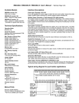
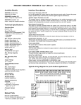
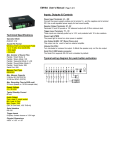
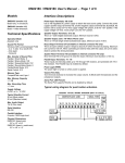
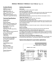
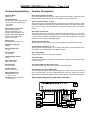
DM3028B / EM3028B User’s Manual - Page 1 of 4
Technical Specifications
Interface Descriptions
Operation Mode
playback only
Power Input Terminals: VD & GD
Use a well regulated DC power supply to obtain the best sound quality. Connect the power
supply’s positive output to terminal VD, and the negative output to terminal GD.
Sound File Format
Windows WAV (uncompressed PCM)
- 22.05 or 44.1 KHz sampling rate
- 16 bit depth
- monaural
Max. Number of Sound Files
Parallel / Direct Mode: 8
Parallel / Binary Mode: 128
Parallel / Sequential Mode: 792
Parallel / Round-Robin Mode: 8
Parallel / Script Mode: 1000
Serial Control: 1000
Memory Type
CompactFlash card, type I, 5V
Max. Memory Capacity
512MB
Speaker Output Terminals: S1 & S2
The speaker output is bridged (balanced). Depending on the ambient temperature, additional heat ventilation may be required to obtain maximum output. If the built-in power amplifier is not to be used, it can be disabled by moving the on-board jumper J3 to the OFF
position.
Busy Output Terminal: BY
This output is taken from a transistor’s collector and internally pulled up to +5V through a
10K resistor (R13). It drops to about 0.2V when the board is playing. Maximum sink current
is 100 mA. When controlling an external relay, be sure to remove resistor R13, and add a
protection diode as shown in the diagram below.
System Reset Terminal: RS
Short terminal RS to the ground to reset the board. Minimum reset duration is 100 ms.
Max. Recording Time
> 1 hour
Parallel Interface Terminals: T1 - T8
These inputs are internally pulled up to +5V through 10K resistors, and protected with 1K inline resistors. The Parallel Interface is enabled by default.
Supply Voltage
10 ~ 32 VDC
Power Light (PWR)
The power light is turned on when power is applied.
Typical Standby Current
150 mA
Max. Audio Output
40W (8 Ohm load)
Serial Interface
RS-232 / RS-485
Parallel Interface
8 inputs, CMOS level
Physical Dimensions
DM3028B (board only)
5.6” x 4.2” x 1.3”
EM3028B (board + metal case)
6.0’’ x 4.8’’ x 1.7”
Volume Pot (VOL)
Turn the knob clockwise to increase the output volume. It affects only the speaker output,
not the line output.
Line Output (LINE): 1/8” Mono Phone Jack
This jack provides single ended line output for external amplification.
Serial Interface Connector: DB9 Female
The Serial Interface supports either RS-232 (default) or RS-485, but not both at the same
time. To select RS-485, move the on-board jumper J2 to the “485” setting. Note that the
Serial Interface is disabled by default, and it is mutually exclusive with the Parallel Interface.
Typical wiring diagram for push button activation.
DM3028B / EM3028B User’s Manual - Page 2 of 4
Trigger Modes
Playback Modes
The Trigger Mode defines how the playback is to be triggered via
the Parallel Interface which has 8 inputs labeled T1 through T8. All
inputs are internally connected to +5V through 10K resistors. If left
unconnected, an input is at +5V (logic “1”). The Trigger Mode does
not apply when the system is controlled via the Serial Interface.
The Playback Mode defines how the playback is to proceed. The
Playback Mode does not apply when the system is controlled via
the Serial Interface.
Direct Trigger
The file is played once per trigger. The playback is not interruptible
except by the system reset. Looping is possible by applying a constant trigger on the input.
In this mode each input directly triggers a corresponding file: T1 =
File 001, T2 = File 002, ......, T8 = File 008.
A trigger is valid when the input is shorted to the ground for at least
50 ms. The Direct Trigger is prioritized from T1 (the highest) to T8
(the lowest). However, it does not mean a higher priority input can
interrupt a lower one. It only means that if multiple triggers are
applied at the same time, the highest priority wins.
Non-interruptible Playback
Interruptible Playback
The file is played once per trigger if not interrupted. The playback
does not start until the trigger is removed (input returns to +5V),
and it can be interrupted by a later trigger on any input. Looping is
not possible.
Binary Trigger
Holdable Playback
Use the Binary Trigger to trigger up to 128 different files ranging
from 001 to 128. The Binary Trigger is often preferred when the
system is controlled by an external controller because it requires
less I/O ports in most cases.
The file is played for as long as the input is triggered, looping if
necessary. It is not interruptible except by the system reset.
To trigger a particular file, the first step is to signal the file number
on T1 (LSB) ~ T7 (MSB). The signal must be in the binary format
with +5V being logic “1”, and 0V (the ground) being logic “0”. For
example, to signal File 007 (binary code “0000111”), T1 ~ T3 should
be at +5V, and T4 ~ T7 should be at 0V. Note that, as a special
case, the binary code for File 128 is “0000000”.
The second and the last step is to short T8 to the ground for at
least 50 ms while maintaining the signal on T1 ~ T7. Afterwards,
signals on T1 ~ T7 don’t matter any more.
Sequential Trigger
Use the Sequential Trigger to sequentially trigger up to 99 different
files per input, as defined below:
T1 triggers File 001 ~ 099
T2 triggers File 201 ~ 299
......
T8 triggers File 801 ~ 899
Each trigger on the same input activates a different file in the sequence. The sequence automatically restarts either when the end
of the sequence is reached or when there is a break in the sequence. For example, if there are three files for T1: 001, 002, and
004, the system will only sequence between 001 and 002. File 004
will never be played because File 003 is missing.
The Sequential Trigger is prioritized from T1 (the highest) to T8
(the lowest). However, it does not mean a higher priority input can
interrupt a lower one. It only means that if multiple triggers are
applied at the same time, the highest priority wins.
Round-Robin Trigger (firmware 1.6 and above)
This mode is very similar to the Direct Trigger mode except that the
inputs are not prioritized. So if multiple inputs are tied to ground
then their files will be played one after another, instead of just the
highest priority one. Round-Robin mode can only be used in
conjuction with Non-interruptible Playback and Script Playback.
Script Playback (firmware 1.5 and above)
Instead of playing a single file, Script Playback executes a series
of playback steps for each trigger. Written in the configuration file,
the Playback Script consists of multiple lines each defining the steps
for a particular trigger in the following format:
?###=Step1,Step2...
Here “###” is the trigger number and “?” is one of the following:
N - Non-interruptible
I - Interruptible
H - Holdable
There are three types of Steps:
F### - play File ###
W##### - wait ##### units of 0.1 second
J### - jump to trigger ###
Here is an example:
DS (or BS)
N001=F007,W00030,F899,J168
I168=F001,W36000,J168
H033=F273
END
When Script 001 is triggered, the system will play File 007, wait 3
seconds, play File 899 and then jump to Script 168. Script 168 is
an endless loop that plays File 001 once every 3600 seconds. But
since Script 168 is interruptible, this endless loop can be broken
by any later trigger.
Put the word END at the end of the Script. You may add comments
after END as they will not be read by the system.
In the DS (Direct Script) mode, Script 001 ~ 008 are triggered via
T1 ~ T8 respectively, but other scripts can only be triggered via the
J(ump) command. In the BS (Binary Script) mode, Script 001 ~
128 are triggered with the Binary Trigger method, but other scripts
can only be triggered via the J command.
Upon powerup or reset, the system will automatically executes
Script 000 once if it exists.
DM3028B / EM3028B User’s Manual - Page 3 of 4
Serial Interface
Serial Commands
When the serial interface is enabled, all parallel inputs are disabled and parallel related modes are no longer applicable.
Play File
DTE Sends: F### (### is the three-digit file number)
System Confirms: f### (### is the same file number as above)
The serial interface consists of a female DB9 connector supporting either RS-232 or RS-485, but not both at the same time. The
default selection is RS-232. To use RS-485, you must move the
on-board jumper J2 to the “485” setting.
On the DB9 connector, three pins are used for RS-232: pin 2 for
RX, pin 3 for TX, pin 5 for ground. Two pins on the same connector
are used for RS-485: pin 1 for negative, pin 9 for positive.
The hardware protocol is fixed at 9600 baud, eight data bits, no
parity and one stop bit (9600, 8N1). Other protocols may be supported by special request.
For RS-232 applications, the system (a DCE device) is connected
to a DTE device (such as a PC) with a regular serial cable (not a
null modem cable). For RS-485 applications, up to 32 systems,
each assigned with a unique address, can be daisy chained on the
same bus with a 2-wire cable.
To enable the serial interface on the system, the configuration file
must contain a two-digit address ranging from “01” to “32”. This
address assignment seems unnecessary for RS-232 applications
because RS-232 is a one-to-one interface. But it is necessary for
us because we want to provide a uniform protocol for both RS-232
and RS-485.
The benefit of a uniform protocol is that it allows us to control multiple systems from a DTE which has only a RS-232 port. In this
case a RS-232 to RS-485 hardware converter is needed to convert
the DTE’s RS-232 port into a RS-485 port.
The communication protocol uses software handshake on a perbyte basis. That is, for every byte it receives, the system sends an
confirmation byte to the DTE. The DTE must not send the next byte
until it receives the confirmation (one exception explained below).
A communication session always starts with a selection process.
The DTE should first sends out an ASCII “A” which, as the only
exception, will not be confirmed by any system on the bus. The
DTE should then sends a binary coded address byte ranging from
1 to 32. If there is a system with the matching address, it will respond by sending back an ASCII “a” within 100 ms. Otherwise the
selection process has failed and should be restarted.
Once the selection process is finished successfully, the DTE can
issue one of the following (ASCII coded) commands, one byte at a
time. For each byte sent, the DTE should expect to receive a proper
confirmation within 100 ms. If the confirmation is missing or invalid, the whole session must be aborted.
The serial interface can be easily tested using a Windows utility
program called “Hyper Terminal” (usually found in Start/Programs/
Accessories/Communications). Hyper Terminal allows you to send
and receive data through the PC’s serial port. All you need to do is
type the letters on the keyboard to send them, and watch the screen
for received data.
Note that to type the binary address on the PC’s keyboard, you
must hold down the ALT key while entering the number on the numerical keypad (make sure the NUM light is on). For example, if
you want to type address “12”, you must hold the ALT key down,
press “1”, “2”, then release the ALK key.
If the file exists, it will be played once. If the file does not exist, the
command will simply be ignored.
If the system is playing or pausing when receiving the “F” command, it will return the error code “e” instead of “f”.
Stop Playback
DTE Sends: S
System Confirms: s
If the system is not playing at the time, it will simply ignore the
command. If the system is playing or pausing at the time, it will
terminate the playback.
Pause Playback
DTE Sends: P
System Confirms: p
If the system is not playing at the time, it will simply ignore the
command.
Resume Playback
DTE Sends: R
System Confirms: r
If the system is not pausing at the time, it will simply ignore the
command.
Busy?
DTE Sends: B
System Confirms: b (if busy, including pausing) or s (if not busy)
Error Code
The system will confirm with an “e” if an invalid command is received, or if a valid command is received at the wrong time.
After receiving the error code, the DTE device should restart the
session from the beginning (the selection process).
DM3028B / EM3028B User’s Manual - Page 4 of 4
The Configuration File
Trouble Shooting Guide
By default, the system works in the following mode:
Parallel Control
Direct Trigger
Non-Interruptible Playback
Parallel Interface Related
To operate the system in other modes, you need to create an ASCII
text file called “MODE.TXT” with one of the following two-letter words
on the first line. Note that this file should be the only text file on the
flash card.
DN (Direct, Non-interruptible)
DI (Direct, Interruptible)
DH (Direct, Holdable)
DS (Direct, Script)
BN (Binary, Non-interruptible)
BI (Binary, Interruptible)
BH (Binary, Holdable)
BS (Binary, Script)
SN (Sequential, Non-interruptible)
SI (Sequential, Interruptible)
SH (Sequential, Holdable)
RN (Round-Robin, Non-interruptible)
RS (Round-Robin, Script)
For serial control (RS-232/RS-485), replace the two-letter word with
a two-digit address ranging from “01” to “32”.
For DS and BS modes, enter the Script starting from the second
line. Be sure to add the word END at the end of the Script.
After editing the configuration file, be sure to save it as a “plain text
file”, “ASCII text file”, or simply “text file”. The system may not work
if the configuration file is not created properly.
File Number Assignment
Sound files on the flash card must be assigned a unique file number for identification. The file number must always be three digits
ranging from 001 to 999. Simply add the file number to the beginning of the original filename, for example: “001Bluejay.wav”.
1. Plays no sound at all.
a. File numbers are not assigned properly.
b. The system is in the wrong mode due to missing or incorrect
configuration file.
c. If the flash card is inserted when the power is on, the system
may not work. To fix this problem, turn the power off for a few
seconds to reset the system.
d. Some CF cards, especially if they have been used in digital
cameras, need to be reformatted with the FAT16 file system.
e. The output volume may have been set too low. Try turning it up.
2. Plays a wrong File.
a. File numbers are not assigned properly.
b. The system is in the wrong mode due to missing or incorrect
configuration file.
3. Plays trashy sounds.
It’s probably due to unsupported file formats such as 8-bit resolution and ADPCM coding. Re-digitize or convert the file into a supported format.
4. Playback speed is too slow/fast.
Unsupported sampling rates may result in wrong playback speed.
Re-digitize or convert the file into a supported sampling rate.
5. Plays a popping/bursting noise once in a while.
The speed of the flash card is too slow. Use a faster flash card or
convert the file to a lower sampling rate.
Serial Interface Related
6. The DTE device receives strange characters.
Make sure the DTE device’s serial port setting is 9600 baud, 8
data bits, no parity, 1 stop bit.
7. RS-232 does not support multiple unit addressing. Does the
DTE device still need to send the address byte after sending
the initial letter “A”?
Yes. It is because the protocol is designed to be uniform for both
RS-232 and RS-485.