1
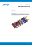
APPLICATION NOTE
ATtiny1634-EK1 User Guide
Atmel ATAN0080
Features
● Atmel® ATtiny1634 MCU
● Atmel ATA663254 SBC – LIN transceiver with integrated voltage regulator
● Touch
● Three Atmel QTouch® buttons
● One Atmel QTouch slider
● Analog I/O
● One potentiometer connected to the ADC of the Atmel ATtiny1634 MCU
● Digital I/O
● Six user LEDs
● Various headers for direct access
● Two possible power sources for the Atmel ATtiny1634 MCU
● Voltage regulator of the Atmel ATA663254 SBC
● External 5V header
● Connectivity
● LIN Bus
Kit Contents
● Boards:
● 1x ATABtiny1634A-V1 – ATtiny1634 MCU with ATA663254 LIN SBC demonstrator
(slave board) with touch sensors
● 1x ATmega64M1 Xplained – LIN to USB gateway
● Other accessories.
● 1x 12V power supply
9341A–AVR–12/13
1.
Introduction
1.1
Kit Overview
The Atmel® ATAtiny1634-EK1 automotive evaluation kit provides a hardware platform for evaluating the Atmel ATtiny1634
automotive MCU and Atmel ATA663254 SBC and for developing software for the Atmel ATtiny1634 MCU. The Atmel
ATtiny1634 is a high-performance, low-power AVR® microcontroller with 16KB of in-system self-programmable Flash memory
and 1KB of internal SRAM designed specifically for automotive applications. The ATABtiny1634A board included in the kit
interfaces the ATtiny1634 MCU to different types of I/O signals. The board also provides interfaces to several capacitive touch
buttons and one capacitive touch slider as well as six LEDs and a potentiometer. The Atmel ATA6632 SBC integrating the LIN
transceiver along with a voltage regulator and a watchdog enables the LIN bus functionality. In addition to the variety of I/Os
provided directly on the board, all MCU I/O signals are made available on the header pins to support easy connection to
external I/Os. When combined with available embedded software, the ATABtiny1634A board is an ideal platform for initial
development of customer-specific applications.
To facilitate the connection to a LIN bus, the kit includes an ATmega64-M1 Xplained board programmed to act as a
USB-to-LIN gateway. Using this gateway, the ATABtiny1634A board can be connected to an available PC GUI application to
monitor and control the on-board I/Os. More generally, the PC GUI application could be used along with the gateway board to
simulate LIN master traffic to aid in the development of an ATABtiny1634A board LIN slave application.
This kit is supported by standard Atmel AVR development tools available at
http://www.atmel.com/design-support/software-tools/default.aspx.
The kit offers a set of features that enables the user to get started right away and gain an understanding of how to integrate the
ATtiny1634-EK and the Atmel ATA663254 within their own design.
Figure 1-1. ATABtiny1634A_V1 PCB
Atmel ATAN0080 [APPLICATION NOTE]
9341A–AVR–12/13
2
2.
Getting Started
2.1
Quick Start
There are several ways to supply power to the kit.
2.1.1
Kit Power Supply via a VBat Supply Voltage
This is the easiest way to supply the kit with power. When using this method, please note that power for the entire board is
supplied by the Atmel® ATA663254 LIN SBC and is therefore limited to a maximum of 85mA. The following steps ensure correct
functionality:
1. Mount the J2, J3, and J11 jumpers.
2.
2.1.2
Connect the 12VDC power supply plug to the X2 power input socket on the ATABtiny1634A-V1 PCB to supply the
board with power.
Supplying Power to the MCU and the LIN SBC Independently
This power supply variant allows more current to be driven than is available from the LIN SBC by supplying the current from an
externally regulated 5VDC power supply.
1. Mount the jumper J11 (if the transceiver is to be used).
2.
Remove the J2 and J3 jumpers. Connect +5VDC to J2 - VCC_MCU and to J3 - VCC_IO as indicated in Figure 2-1.
The pins on J5/VCC_IO and J5/VCC_CPU can alternatively be used.
Figure 2-1. Independent MCU and LIN SBC Power Supply
3.
Connect +7 to +28VDC to X2 (if the transceiver is to be used). The power LED D8 only lights up if J11 is mounted and
sufficient voltage is supplied to X2.
Atmel ATAN0080 [APPLICATION NOTE]
9341A–AVR–12/13
3
2.1.3
Connecting the USB-to-LIN Bridge
The ATmega64M1 Xplained board is used to bridge all LIN messages to USB and vice versa. It can be used with the supplied
GUI as well to monitor the status of the touch buttons, potentiometer and to control the LEDs.
The LIN, LIN_VS (supply voltage), and GND lines between the ATmega64M1 Xplained and the ATABtiny1634-V1 have to be
connected using the J5 header on the ATABtiny1634 and the corresponding header on the ATmega64 Xplained. Care has to be
taken when setting up the connection. When making the connections as shown in Figure 2-2, the outer red and black cables
cross the middle cable. The pin descriptions on the silkscreen should be read carefully.
Figure 2-2. LIN Connection
2.1.4
Configuring the ATmega64M1 Xplained
The following points need to be considered when using the ATmega64M1 Xplained as a USB-to-LIN bridge. For a more detailed
description of the board, please refer to the ATmega64M1 Xplained hardware user guide.
1. 5VDC power supply is provided to the ATmega64M1 by connecting the VCC_MCU (marked in green) (e.g., J300/pin)
to any of the USB 5V output sources (marked in red, e.g., VCC_5V_USB (onboard) on J406/pin 1 or J3/pin10).
Please see example in Figure 2-3.
Note:
If there is an existing jumper on the J201 header (VCC_MCU and VCC_P3_V3 pins), it must be removed.
Atmel ATAN0080 [APPLICATION NOTE]
9341A–AVR–12/13
4
Figure 2-3. Voltage Domain VCC_MCU
2.
2.2
VS_LIN, LIN, and GND must be connected to the corresponding signals on the ATABtiny1634-V1.
Design Documentation and Related Links
The following list contains links to the most relevant documents and software for the ATtiny1634-EK1.
1. ATtiny1634-EK1 Design Documentation – package containing schematics, BOM, assembly drawings, 3D plots, layer
plots, software, etc.
2.
Atmel® Studio (http://www.atmel.com/atmelstudio) – free Atmel IDE for development of C/C++ and assembler code
for Atmel microcontrollers.
3.
IAR Embedded Workbench® (http://www.iar.com/en/Products//IAR-Embedded-Workbench/AVR/) is a commercial
C/C++ compiler that is available for AVR® devices. There is a 30-day evaluation version as well as code size limited
kick-start version available from the IAR website.
4.
Device samples can be ordered from Atmel sample store (http://www.atmel.com/system/samplestore).
Atmel ATAN0080 [APPLICATION NOTE]
9341A–AVR–12/13
5
3.
Headers, Connectors, and Jumpers
The ATABtiny1634A-V1 has several headers, connectors, and jumpers to configure and connect the board to different
applications.
Table 3-1.
Headers Overview
Header
Designator
J1
J1 (1x2) multiplexes PC5 and PC4 ports of the Atmel ATtiny1634 MCU between LEDs and XTAL pins.
J2
J2 (1x2) connects the Atmel ATtiny1634 VCC_CPU power pin to the VCC_VREG voltage regulator
output. Please note that the VREG output of the Atmel ATA663254 is limited to 85mA.
J3
3.1
Description
J3 (1x2) connects the VCC_IO power pin to the VCC_VREG voltage regulator output. Please note that
the VREG output of the Atmel ATA663254 is limited to 85mA. VCC_IO is the supply voltage for the
LEDs, the potentiometer and is available on several headers.
J4
J4 (1x2) can be used to enable the pull-up resistor needed for a LIN master node. The jumper on this
header should be removed when operating the board as a LIN slave node.
J5
J5 (1x8) connects ATABtiny1634A-V1 PCB to external power supply (VCC, LIN_VS), GND, LIN IO pin,
VCC_VREG, and external power supplies (VCC_MCU, VCC_IO).
J6
J6 (2x6) connects the Atmel ATtiny1634 IO ports to the D0-D5 LEDs.
J7
J7 (2x3) is used as the ISP header.
J8
J8 (2x3) provides access to the Atmel ATtiny1634 ports (PB1, PB2, PC3), AREF, VCC_IO, and GND
pins.
J9
J9 (2x6) connects the Atmel ATtiny1634 to the QTouch on-board sensors, i.e., three buttons or a slider.
Place 1x2 jumpers across to connect the on-board buttons or a slider.
J10
J10 (1x2) connects the NRES of the Atmel ATA663254 LIN SBC to the NRES of the ATtiny1634 MCU.
J11
J11 (1x2) connects the external power supply on X2 to LIN_VS.
J12
J12 (1x2) is the autobaud enable header. It can be used to connect RXD1 to IC1 (Timer1/Counter1) to
measure sync bytes on RXD1.
J13
J13 (1x3) provides QTouch debug mode digital outputs.
J14
J14 (1x2) is a potentiometer enable header. Connects the potentiometer output to PB0 using a jumper.
J15
J15 (2x6) multiplexes between QTouch sensors. Selects either three buttons (CS2, CS3, CS4) or one
slider (CS1).
Detailed Description of the Headers
Table 3-2.
J1 Header (XTAL/LED)
Pin
Description
1
LED3
2
LED2
3
PC5
4
PC6
5
External crystal pin 1
6
External crystal pin 3
Atmel ATAN0080 [APPLICATION NOTE]
9341A–AVR–12/13
6
Table 3-3.
J5 Header (IO)
Pin
Description
1
GND
2
LIN
3
LIN_VS
4
GND
5
VCC_CPU
6
VCC_IO
7
VCC_VREG
8
GND
Table 3-4.
J6 Header (LEDs)
Pin
Description
1
PORTC2
2
LED0 cathode
3
PORTA1
4
LED1 cathode
5
PORTC4
6
LED2 cathode
7
PORTC5
8
LED3 cathode
9
PORTC0
10
LED4 cathode
11
PORTC1
12
LED5 cathode
Table 3-5.
J7 Header (ISP)
Pin
Description
1
MISO
2
VCC_IO
3
SCK
4
MOSI
5
NRES
6
MOSI
Table 3-6.
J8 Header
Pin
Description
1
PB1
2
PB2
3
PC3
4
AREF
5
GND
6
VCC_IO
Atmel ATAN0080 [APPLICATION NOTE]
9341A–AVR–12/13
7
Table 3-7.
J9 Header
Pin
Description
1
J15 pin 2
2
R5 (touch channel 2 K), C6 (touch channel 2S)
3
NC
4
NC
5
J15 Pin 6
6
R4 (touch channel 1 K), C7 (touch channel 1 S)
7
NC
8
NC
9
J15 pin 10
10
R3 (touch channel 0 K), C8 (touch channel 0 S)
11
NC
12
NC
Table 3-8.
J13 Header (QTouch Debug)
Pin
Description
1
GND
2
MOSI
3
SCK
Table 3-9.
J15 Header (QTouch Sensor)
Pin
Description
1
QTouch slider channel 2 – end electrodes
2
J9 pin 1
3
NC
4
QTouch button CS4
5
QTouch slider channel 1
6
J9 pin 5
7
NC
8
QTouch button CS3
9
QTouch slider channel 0
10
J9 pin 9
11
NC
12
QTouch button CS2
Atmel ATAN0080 [APPLICATION NOTE]
9341A–AVR–12/13
8
4.
Peripherals
4.1
QTouch Sensors
The QTouch algorithms enable either the three QTouch buttons or the QTouch slider to be used.
Obviously, the software used should match the connected sensors. The software shipped with the kit uses the slider in standalone mode. To evaluate the use of the buttons in stand-alone mode, the source initializing the touch functionality located in the
main.c file must be changed.
/* Init Touch */
AtaDevTouch_init(QT_SENSOR_SLIDER);
qt_sensor_flag = QT_SENSOR_STATE_SLIDER;
to
/* Init Touch */
AtaDevTouch_init(QT_SENSOR_BUTTONS);
qt_sensor_flag = QT_SENSOR_STATE_BUTTONS;
Alternatively, the GUI-connected mode can be used to evaluate the buttons as described in Section 5.2 “GUI-Connected Mode”
on page 10. The jumpers on header J15 must be connected as shown below to use the CS2 to CS4 QTouch buttons.
Table 4-1.
J15 Header in Button Configuration
J15 Header Pins
Pin 2 – Pin 4
Pin 6 – Pin 8
Pin 10 – Pin 12
The jumpers on header J15 must be connected as shown below to use the CS1 QTouch slider.
Table 4-2.
J15 Header in Slider Configuration
J15 Header Pins
Pin 1 – Pin 2
Pin 5 – Pin 6
Pin 9 – Pin 10
In either method, the following pins on the J9 header must be connected: 1-2, 5-6, 9-10.
4.2
LEDs
Six LEDs can be used to display the status of the application. The relevant headers are J6 and J1. To use the LEDs, the pins on
the J6 header must be connected 1-2, 3-4, etc. To use the LED2 and LED3, it is also necessary to connect the jumpers on pins
2-4 and 1-3 on the J1 header so that the Atmel® ATtiny1634 MCU port can be connected directly to the LEDs. The J1 header
must be configured correctly to enable PC4-LED2 and PC5-LED3 connections; alternatively, the J1 header can be used to
supply an external oscillator or a clock to the microcontroller.
LED5 can only be used if the J12 autobaud jumper is not mounted and the autobaud feature is disabled. This requires
recompiling the software or using the GUI to deactivate autobaud.
4.3
Potentiometer
A potentiometer can be connected to an Atmel ATtiny1634 MCU port pin to evaluate the ADC. The potentiometer is connected
to VCC_IO and GND, resulting in the full ADC range being used when AREF=VCC_IO is used. Jumper J14 has to be mounted
to use the potentiometer.
Atmel ATAN0080 [APPLICATION NOTE]
9341A–AVR–12/13
9
5.
Example Software User Guide
The example software delivered with this board demonstrates some of the basic functions of the Atmel® ATTiny1634 and the
Atmel ATA663254. Depending on whether the supplied GUI is to be used, the software implements two different working
modes.
5.1
ATABtiny1634A-V1 in Stand-Alone Mode
The ATABtiny1634A-V1 and the power supply included in the kit are required for running in this mode. The kit must be
connected as outlined in Section 2.1.1 “Kit Power Supply via a VBat Supply Voltage” on page 3.
The jumpers need to be set to the following positions for the stand-alone mode to work as expected:
● Header J6 - jumpers for LEDs 0-4 mounted 1-2, 3-4,5-6,7-8
●
●
●
●
●
●
●
Jumper J14 mounted
Header J1 mounted 1-3, 2-4
Jumper J2 mounted
Jumper J15 mounted 1-2,5-6,9-10
Jumper J9 mounted 1-2,5-6,9-10
Jumper J11 mounted
Jumper J12 not mounted
With this jumper setting the Atmel ATTiny1634 MCU uses the ADC to continuously measure the QTouch slider and the
potentiometer.
The LEDs D0-D1 display the status of the potentiometer and light up in roughly linear fashion compared to the potentiometer
position.
The D2-D4 LEDs display the status of the Atmel QTouch slider. If the QTouch buttons are to be displayed, the source code has
to be recompiled to use the buttons in stand-alone mode as described in Section 4.1.1 and jumper J15 must be configured to
interface with the QTouch buttons as described in Section 4.1 “QTouch Sensors” on page 9.
5.2
GUI-Connected Mode
A GUI running on a PC host is used to communicate with the gateway via the USB port for sending LIN commands to the LIN
slave node.
System functionality can be summarized as follows:
● ATmega64M1 Xplained PCB is used as the LIN bus gateway and LIN bus master. It uses the USB port to communicate
with the host PC. It also uses the LIN bus and acts as a master for sending LIN messages to the LIN slave.
●
5.2.1
The ATtiny1634A-V1 PCB is used as a LIN bus slave device with QTouch peripherals. The Atmel ATA663254 LIN SBC
transceiver interfaces to the LIN bus. The slave node can detect touch inputs and transmit the touch data on the LIN bus
to the LIN master gateway which then relays it to the host PC for display in the GUI window. By using the GUI on the
host, PC commands can also be sent to the LIN slave PCB, e.g., to switch on the LED. The input from the LIN slave node
can also be displayed in the GUI window, such as for displaying the push button or state of the potentiometer in real time.
Evaluating the System with the GUI
To evaluate operation of the ATABtiny1634A board using the GUI, both the ATABtiny1634A board and the ATmega64M1
Xplained board must be properly configured as described in Section 5.2.2 “Step-By-Step Instructions for Connecting and
Operating the Kit” on page 11. Once both boards are properly configured and interconnected and the ATmega64M1 Xplained
board is connected by USB to a PC, then the GUI on the PC can be used to interact with the ATABtiny1634A board. The
software on the ATABtiny1634A board automatically switches from stand-alone operation to GUI-connected operation when it
detects a valid LIN frame.
Section 6. “GUI User Guide” on page 15 provides more detailed information on how to use the GUI. This mode works in a
manner very similar to stand-alone mode except that the potentiometer reading and the QTouch sensor status is reported to the
GUI via LIN instead of controlling the LEDs, allowing the LEDs to be controlled as outputs from the GUI.
Atmel ATAN0080 [APPLICATION NOTE]
9341A–AVR–12/13
10
5.2.2
Step-By-Step Instructions for Connecting and Operating the Kit
The following section gives step-by-step interconnection and operating instructions.
These are in reference to the interconnection instructions for the ATABtiny1634A-V1 and ATmega64M1 PCBs. System setup
and first-time operation with the GUI is also illustrated. The host GUI reports the interconnection status and depicts LIN frame
TX and RX traffic and contents between the two PCBs.
1. As described in Section 2.1.1 “Kit Power Supply via a VBat Supply Voltage” on page 3, configure the ATABtiny1634AV1 PCB by positioning the jumpers as described here:
●
Connect the jumper at J11 to enable the voltage supply socket on X2 from the wall adapter.
●
Connect J2 (VCC_CPU) and J3 (VCC_IO) to enable VREG output voltage as the voltage source for the IO and
the Atmel ATtiny1634 CPU.
●
Connect jumpers at J9 (pins 1-2, 5-6, 9-10; use three 1x2 jumpers).
●
To use a QTouch slider: Connect the jumpers on J15 (pins 1-2, 5-6 and 9-10) to interface to the QTouch slider.
(Note: the kit is shipped in this default configuration).
●
To use QTouch buttons: Connect jumpers to J15 (pins 2-4, 6-8 and 10-12; use three 1x2 jumpers) to interface to
the QTouch buttons.
●
Connect J1 (pins 1-3, 2-4; use two 1x2 jumpers) to enable D2 and D3 when XTAL (X1) is not used.
●
Connect the J12 (AUTOBAUD) jumper to synchronize the LIN slave baud rate to the LIN master baud rate for the
first time. After successful synchronization, the synchronization timing is stored internally in the slave EEPROM for
future use.
2.
Configure the ATmega64M1 Xplained board as described in Section 2.1.4 “Configuring the ATmega64M1 Xplained”
on page 4 (use a jumper wire to connect the VCC_5V_USB pin to the VCC_MCU pin).
3.
Interconnect the ATABtiny1634A-V1 and ATmega64M1 Xplained boards for LIN communication: Connect the
ATmega64M1 Xplained board GND, LIN, and VS_LIN pins (J205, Figure 2-3 on page 5) to the respective GND, LIN,
and LIN_VS pins on the ATABtiny1634A-V1 board.
4.
Connect the 12VDC power supply plug to the X2 socket on the ATABtiny1634A-V1 board.
5.
Connect the USB cable to the ATmega64M1 Xplained board and the host PC (the new USB device is detected and
the USB driver is automatically installed).
Atmel ATAN0080 [APPLICATION NOTE]
9341A–AVR–12/13
11
Figure 5-1. Correctly Interconnected PCBs
6.
Open the Atmel ATA1634-EK interface GUI by executing ATA1634_GUI.exe supplied in the kit download package.
7.
Once the main window opens, the QTouch sensor configuration can be selected in the board setup section (select
“Buttons” if J15 is configured to sense the QTouch buttons or select “Slider” if J15 is configured to support the slider
functionality) (see Figure 5-2).
Atmel ATAN0080 [APPLICATION NOTE]
9341A–AVR–12/13
12
Figure 5-2. Atmel ATA1634-EK Interface Main Window
Note:
8.
When the USB is properly connected, the “USB Connected” message appears at the bottom of the GUI window
as shown in Figure 5-2. The incrementing frame count is also shown, indicating proper data communication
between the LIN nodes.
Select from the pull-down window: Tools>Status to open the status window (see Figure 5-3).The LIN frame counter
should be incrementing.
Atmel ATAN0080 [APPLICATION NOTE]
9341A–AVR–12/13
13
Figure 5-3. Status Window
9.
Note:
Once the GUI window is opened and the USB cable is connected, the USB LED begins to flash by oscillating
green/red and the LED0 begins to alternate ON and OFF on the PCB of the ATmega64M1 Xplained. The green/red
flashing of the USB LED indicates that the USB connection with the host GUI is correct. The LED0 flashing OFF/ON
means the ATmega64M1 MCU device is executing.
LIN bus communication can only be established if the LED behavior is observed as indicated in step 9 above. If
the GUI window is not opened on the host and/or the host does not have the USB port opened, the USB LED
stays red and the LED0 is OFF and the system is not ready for operation. Reconnect the USB cable and restart
the GUI application to reset the PCB (USB LED must flash green/red and the LED0 must alternate between ON
and OFF.
10. During normal operation, the LIN frame counters should increment while the LIN error counter should stay at zero if
no transmission errors are detected.
Note:
If the “LIN Errors RX'd” parameter shows the error count incrementing and the status frame counter is NOT incrementing in the status window, replace the AUTOBAUD jumper (J12) and cycle the power on the
ATABtiny1634A-V1 PCB to synchronize the LIN slave. Press the “Clear” button to reset the error counter in the
status window. The “LIN Errors RX'd” should stay at zero and the LIN frames counter should increment during normal operation.
11. To test the touch sensors, push the touch buttons on the ATABtiny1634A-V1 PCB and observe the touch detection in
the main GUI window. The LEDs can also be switched ON and OFF by selecting the ON and OFF radio buttons in the
GUI window.
Atmel ATAN0080 [APPLICATION NOTE]
9341A–AVR–12/13
14
6.
GUI User Guide
6.1
Installation
There are no special steps necessary to install the GUI. There is one executable requiring Microsoft .NET 4.0 or later for it to
launch correctly.
6.2
Explanation of Screens
Figure 6-1. Screen 1
Application
1. Tools Menu: Allows selection of the
●
LIN bus analyzer tool – for monitoring LIN bus traffic
●
Send message tool – for sending a user-defined LIN
message
●
Status tool – for viewing connection status counters
2.
Board setup area: For configuring the board for use with
the buttons or with the slider, for enabling QTouch
debugging, and for disabling LIN autobaud.
3.
Board control and status area: For controlling the board
LEDs and viewing the status of the board potentiometer
and QTouch buttons or slider. If connectivity from the
GUI through the gateway to the ATABtiny1634A board
has not been established, the controls are grayed out
(as shown).
4.
USB connection status: Indicates whether the
ATmega64M1 Xplained LIN-USB gateway is connected
or not.
5.
Status frame reception counter: Counts each time a status frame is received from the ATABtiny1634A board; a
continuously increasing count indicates complete connectivity from the GUI through the ATmega64M1
Xplained LIN-USB gateway to the Atmel ATtiny1634
MCU on the ATABtiny1634 board and back.
Atmel ATAN0080 [APPLICATION NOTE]
9341A–AVR–12/13
15
Figure 6-2. Screen 2
Application
Connection to ATABtiny1634A Board Established
1.
Buttons/slider configuration: Configures the
ATABtiny1634A board for operation with either (3x)
QTouch buttons or (1x) QTouch slider or operating without the QTouch buttons or slider. For proper operation,
the board jumpers must be set according to the configuration selected.
2.
Buttons/slider status: Indicates the current status of the
buttons or slider. Activity on the configured sensor on
the board should be reflected on the GUI, e.g., the illustration shows that the CS3 button on the
ATABtiny1634A board is being pressed. The status is
only shown for the configured function; the function that
is not configured is grayed out (e.g., in this case, the
board is configured for buttons, so the slider status is
grayed out).
3.
LED controls: Click ON or OFF to control the
ATABtiny1634A board LEDs; the LEDs on the board will
correspond to the selection on the GUI (assuming the
board jumpers are properly configured).
4.
Potentiometer status: Follows the potentiometer setting
on the ATABtiny1634A board, e.g., rotating the potentiometer on the board should cause a corresponding
change on the GUI.
5.
Stop LIN: Used to stop the transmission of application
messages via the LIN. Press again to restart the message transmission via the LIN.
6.
Sleep: Press to send a sleep message to the
ATABtiny1634A board; once the sleep message is sent,
subsequent LIN messages are automatically stopped
and the Stop LIN button (5) changes to Start LIN.
Press Start LIN to restart the LIN messages and thus
also wake up the board.
7.
Reset: Press to send a reset message to the
ATABtiny1634A board.
8.
Disable Autobaud: Check to disable the LIN autobaud
function.
Note:
The LIN autobaud implementation uses the same
MCU pin as LED5, so LED5 is not enabled when
autobaud is enabled. Before disabling autobaud,
remove the autobaud jumper on the ATABtiny1634A
board.
Atmel ATAN0080 [APPLICATION NOTE]
9341A–AVR–12/13
16
Figure 6-3. Screen 3
LIN Bus Analyzer Tool
1. Launch from the application tools menu → LIN bus
analyzer
2.
The display logs LIN message traffic (most recent messages at the top of the display).
3.
Type field - From the perspective of the GUI acting as a
master P = Publish (GUI sent PID and data)
S = Subscribe (GUI sent PID, slave responded with data)
4.
Stop: Press to stop message logging; changes to start
after being pressed.
5.
Start: Press to start message logging; changes to stop
after being pressed.
The default software supports 2 LIN message frames:
● PID = 06, size = 2 bytes: This frame is published by the GUI
to control the ATAB1634 board, e.g., to turn LEDs ON or
OFF.
●
PID = 03, size = 4 bytes: This frame is subscribed to by the
GUI to obtain the status of the ATAB1634 board, e.g., to
find the current potentiometer reading.
If a response is not received for a message that the GUI
subscribes to, a time-out error is displayed for the frame.
Atmel ATAN0080 [APPLICATION NOTE]
9341A–AVR–12/13
17
Figure 6-4. Screen 4
Send LIN Message Tool
1. Launch from the application tools menu → Send LIN
message
2.
Field for entering the message length, PID and data. All
fields are hexadecimal values.
3.
Use this to select if the message should be sent periodically (repeatedly) or once only (single-shot). Periodic
messages are continuously sent until stopped by the
user (or until this window is closed).
4.
Used to select between subscribe and publish.
5.
Send: Press to send the message. If the message is
periodic, the button changes to stop after being
pressed.
6.
Stop: Press to stop the transmission of a periodic
message.
7.
When a periodic publish message is being sent, data
fields can be altered; the length and PID field cannot be
altered while a periodic publish message is being sent.
Atmel ATAN0080 [APPLICATION NOTE]
9341A–AVR–12/13
18
Figure 6-5. Screen 5
Status Tool
1. Launch from the application tools menu → Connection
status
2.
Displays USB connection status, connection time
(approximately in seconds), and various counters.
3.
Clear: Press to clear the counters.
Atmel ATAN0080 [APPLICATION NOTE]
9341A–AVR–12/13
19
7.
Using QTouch Debug Mode
The QT600 board must be ordered separately and allows QTouch debug mode to be used. The QT600 board is part of the tool
and available here: http://www.atmel.com/tools/QT600.aspx.
The board must be prepared as described below to use the QTouch debug tools supplied with Atmel® Studio.
To prepare the kit for this mode, the ATABtiny1634A-V1 board must be set up as described in Section 2.1.1 “Kit Power Supply
via a VBat Supply Voltage” on page 3.
The connections to the ATmega64M1 Xplained board must also be prepared as described in Section 2.1.3 “Connecting the
USB-to-LIN Bridge” on page 4 and the board itself has power supply as described in Section 2.1.4 “Configuring the
ATmega64M1 Xplained” on page 4.
LEDs 1 to 4 on J8 should never be connected, i.e., the jumpers should not be mounted.
When connecting the power and starting the GUI as described in Section 6. “GUI User Guide” on page 15, updates should be
sent from the board to the GUI. If the connection has been successfully established, this is indicated by the “USB connected”
message and the number of received frames continuously increasing on the lower right corner of the window as indicated in
Figure 7-1.
Figure 7-1. Check Connection
If the connection is working properly, the QTouch debug pins can be enabled by checking the “Enable QTouch Debug”
checkbox.
The QT600 board must then be connected via SPI to the ATABtiny1634A PCB. Table 7-1 illustrates the necessary connections:
Table 7-1.
Connecting Header Touch Data with J6 on ATABtiny1634A-V1
Header Touch Data on QT600
Header J6 on ATTiny1634
5
5
6
9
7
3
8
7
GND
GND
Atmel ATAN0080 [APPLICATION NOTE]
9341A–AVR–12/13
20
8.
Software Programming and Debugging
Standard debugging and programming tools can be connected to the ATABtiny1634A board using the J7 6-pin ISP header. To
establish a connection to a programmer, the autobaud jumper J12 and the jumper on J6 connecting LED5 must be removed.
The NRST jumper should also be removed to avoid tool connection problems.
Atmel ATAN0080 [APPLICATION NOTE]
9341A–AVR–12/13
21
Atmel Corporation
1600 Technology Drive
Atmel Asia Limited
Unit 01-5 & 16, 19F
Atmel Munich GmbH
Business Campus
Atmel Japan G.K.
16F Shin-Osaki Kangyo Building
San Jose, CA 95110
BEA Tower, Millennium City 5
Parkring 4
1-6-4 Osaki
USA
418 Kwun Tong Roa
D-85748 Garching b. Munich
Shinagawa-ku, Tokyo 141-0032
Tel: (+1) (408) 441-0311
Kwun Tong, Kowloon
GERMANY
JAPAN
Fax: (+1) (408) 487-2600
HONG KONG
Tel: (+49) 89-31970-0
Tel: (+81) (3) 6417-0300
www.atmel.com
Tel: (+852) 2245-6100
Fax: (+49) 89-3194621
Fax: (+81) (3) 6417-0370
Fax: (+852) 2722-1369
© 2013 Atmel Corporation. All rights reserved. / Rev.: 9341A–AVR–12/13
Atmel®, Atmel logo and combinations thereof, Enabling Unlimited Possibilities®, AVR®, QTouch®, and others are registered trademarks or trademarks of Atmel
Corporation or its subsidiaries. Other terms and product names may be trademarks of others.
Disclaimer: The information in this document is provided in connection with Atmel products. No license, express or implied, by estoppel or otherwise, to any intellectual property right is granted by this
document or in connection with the sale of Atmel products. EXCEPT AS SET FORTH IN THE ATMEL TERMS AND CONDITIONS OF SALES LOCATED ON THE ATMEL WEBSITE, ATMEL ASSUMES
NO LIABILITY WHATSOEVER AND DISCLAIMS ANY EXPRESS, IMPLIED OR STATUTORY WARRANTY RELATING TO ITS PRODUCTS INCLUDING, BUT NOT LIMITED TO, THE IMPLIED
WARRANTY OF MERCHANTABILITY, FITNESS FOR A PARTICULAR PURPOSE, OR NON-INFRINGEMENT. IN NO EVENT SHALL ATMEL BE LIABLE FOR ANY DIRECT, INDIRECT,
CONSEQUENTIAL, PUNITIVE, SPECIAL OR INCIDENTAL DAMAGES (INCLUDING, WITHOUT LIMITATION, DAMAGES FOR LOSS AND PROFITS, BUSINESS INTERRUPTION, OR LOSS OF
INFORMATION) ARISING OUT OF THE USE OR INABILITY TO USE THIS DOCUMENT, EVEN IF ATMEL HAS BEEN ADVISED OF THE POSSIBILITY OF SUCH DAMAGES. Atmel makes no
representations or warranties with respect to the accuracy or completeness of the contents of this document and reserves the right to make changes to specifications and products descriptions at any time
without notice. Atmel does not make any commitment to update the information contained herein. Unless specifically provided otherwise, Atmel products are not suitable for, and shall not be used in,
automotive applications. Atmel products are not intended, authorized, or warranted for use as components in applications intended to support or sustain life.