1
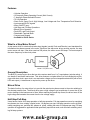
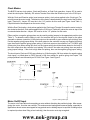
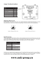
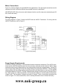
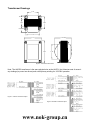
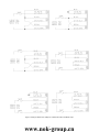
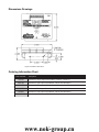
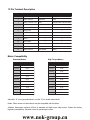
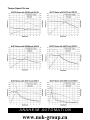
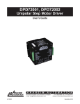
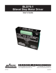
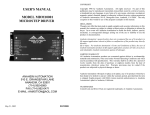
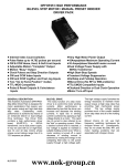
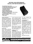
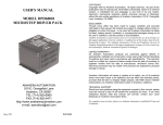
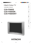
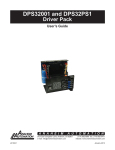
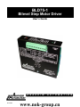
BLD75-1
Bilevel Step Motor Driver
User’s Guide
A N A H E I M
#L010125
A U T O M A T I O N
www.nok-group.cn
1
Features
• Unipolar Operation
• 10 Amps per Phase Operating Current (Kick Current)
• 7 Amps per Phase Standstill Current
• 70 Volt Operation
• Short Circuit, Open Circuit, High Voltage, Low Voltage and Over Temperature Fault Detection
• Inputs accept 24VDC signals
• Motor ON/OFF Input
• Half-Step and Full-Step Operations
• Bilevel Driver Operation
• Fault LED, and Fault Output
• Detachable Terminal Block
• Compact and Rugged
• Available in Driver Packs
What Is a Step Motor Driver?
A step motor driver is a device that takes input signals (usually Clock and Direction) and translates this
information into phase currents in the motor. Each time the step motor driver receives a pulse, the step
motor moves one step. If the driver receives 200 pulses, the motor moves 200 steps. The motor steps at
the same frequency as the clock pulses.
FIGURE 1: Step Motor Driver
General Description
The BLD75 is a step motor driver that can drive motors rated from 1 to 7 amps/phase (unipolar rating). It
can handle 6 lead and 8 lead motors. This driver features a unipolar bilevel (or dual voltage) drive technique with short circuit, open circuit, over and under voltage, and over temperature detection (with a Fault
LED and output). A transformer is required to power up the driver.
Bilevel Drive
The basic function of a motor driver is to provide the rated motor phase current to the motor windings in
the shortest possible time. The bilevel driver uses a high voltage to get a rapid rate of current rise in the
motor windings in the least amount of time. When reaching the preset trip current, the driver turns off the
high voltage and sustains the current from the low voltage supply.
Half-Step/Full-Step
Users have a choice of full-step operation or half-step operation. Full-step operation occurs by energizing
two phases at a time, rotating a typical motor 1.8 degrees per step. Half-step operation occurs by alternately energizing one, and then two, phases at a time, rotating the motor 0.9 degrees per step. Full-step
operation is suggested for applications that specifically require that mode, such as when retrofitting existing full-step systems.
www.nok-group.cn
2
Clock Modes
The BLD75 has two clock options: Clock and Direction, or Dual Clock operation. Jumper JP2 is used to
select the clock option. Basically JP2 selects Terminal 5 as either the Direction input or the CCW input.
With the Clock and Direction option (most common option), clock pulses applied to the Clock input (Terminal 6) cause the motor to step. The direction of the motor is determined by the logic level of the Direction
input (Terminal 5). Jumper JP2 must be in the “2-3” position for this mode (see Figure 4 and Table 1).
Physical direction also depends on the motor wiring.
With the Dual Clock option, clock pulses applied to the Clock input (Terminal 6) cause the motor to step in
the clockwise direction. Clock pulses applied to the CCW input (Terminal 5) cause the motor to step in the
counterclockwise direction. Jumper JP2 must be in the “1-2” position for this mode.
Either positive or negative going pulses may be used by setting jumpers in the appropriate position (see
Table 1). To determine which setting to use, first consider the type of clock pulse output on the pulse
generator or indexer (controller). If the clock output on the controller is open-collector type (sinking), then
use the negative going jumper setting. If the clock output on the controller is a pnp or p-channel (sourcing)
type, then use the positive going jumper setting. If the clock output on the controller is a TTL/CMOS type
(totem pole), then either setting will work; but the jumper setting should be chosen based on the level of
the clock output when the controller is not pulsing. If the clock is low when not pulsing, then use positive
going jumper settings. If the clock is high when not pulsing, then use the negative going jumper setting.
The clock inputs (Clock and CCW) are pulled up to +5Vdc through a 10K ohm resistor for negative going
clock inputs; or pulled down to 0VDC through a 10K ohm resistor for positive going clock inputs. The
pullups/pulldowns are followed by an RC filter. See Figure 2 and Figure 3.
Figure 2: Sourcing Clock Input
Figure 3: Sinking Clock Input
Motor On/Off Input
The motor on/off input allows de-energizing a motor without disturbing the positioning logic. After reenergizing the motor, a routine can continue. This reduces motor heating and conserves power, especially in
applications where motors are stopped for long periods and no holding torque is required. If holding torque
is required (such as when lifting a load vertically), then the motor must stay energized.
www.nok-group.cn
3
Jumper Functions/Locations
Function
JP 1 JP 2 JP 3
Negative Going Clocks
1-2
X
X
Positive Going Clocks
2-3
X
X
Terminal 5 = CCW
X
1-2
X
Terminal 5 = Direction
X
2-3
X
Low Voltage Fault Detection Enabled
X
X
1-2
Low Voltage Fault Detection Disabled
X
X
2-3
Standard Product
1-2
2-3
2-3
Figure 4: Jumper Location Drawing
Adjusting Kick Current
By following the instructions on the cover, use a small screwdriver to adjust the potentiometer. Line up
the potentiometer’s arrow to the number corresponding to the motors rated current (amps/phase).
4
4
3
3
5
1
6
2
6
2
5
1
7
Example 1: 23D104 Motor, Set to 2.0A.
7
Example 2: 34D314 Motor, Set to 7.0A.
Fault Protection
There are five types of fault detection. When a fault is detected, the driver turns off the motor current, the
red fault LED indicates which type of fault occurred and the Fault Output (pin 10) goes low. This output is
able to stand off 50V and sink 50mA. Refer to the table below for LED fault indications.
# o f L E D B l i n k s F au l t C o n d i t i o n
1
Short or Over C urrent
2
Open Motor or
C onnecti on
3
Hi gh Voltage Too Hi gh
4
Low Voltage Too Low
5
Over Temperature
If a fault occurs, reset the fault by applying a logic “0” to the Reset Fault Input (pin 4) for at least 100ms or
by cycling power off for at least 15 seconds. After resetting, try to run the motor again. If the driver
continues to fault, check the conditions listed in the troubleshooting section on page 11.
www.nok-group.cn
4
Motor Connections
Figure 5 is a hookup diagram for typical BLD75 driver applications. The input signal connections must be
separate from motor connections and all other possible sources of interference.
IMPORTANT NOTE: When the motor cable between the driver and the step motor extends beyond 25
feet, consult the factory.
Wiring Diagram
The wiring diagram in Figure 5 shows the BLD75 with the AA2791 Transformer. For wiring with the
AA2793 Transformer, refer to Figure 9.
Figure 5: Hook Up Drawing
Power Supply Requirements
The BLD75 must be powered by a recommended Anaheim Automation transformer. The AA2791 transformer and the AA2793 transformer are the most commonly used and are both rated for 300VA. These
transformers have a high voltage winding, a low voltage winding, and a logic voltage winding. The AA2793
has two high voltage windings and two low voltage windings for powering two BLD75’s. The high voltage
winding (yellow) and low voltage winding (red) plug into the quick disconnects on the back of the BLD75
(see hookup diagram in Figure 5). The logic voltage winding (orange) is used to power up optional controllers. When using one of these transformers, the nominal low-voltage is 5.0 volts and the nominal highvoltage is 60V. The transformer voltages are shown in Figures 7 and 8; the physical dimensions are
shown in Figure 6. For other transformers, refer to ordering information chart or contact the factory.
www.nok-group.cn
5
Transformer Drawings
2.350
.800 MAX
2.500
1.500
1.450 MAX
3.000
3.750 MAX
3.570
4.500
3.100
Figure 6: Transformer Dimensions
Note: The AA2793 transformer is the same physical size as the AA2791, but it has two sets of secondary windings (to power two drivers) and a dual primary winding for 115/230V operation.
Figure 7: AA2791 Transformer Specs
Figure 8: AA2793 Transformer Specs
www.nok-group.cn
6
Figure 9: Wiring for different line voltages for transformers with a 90-265VAC input
www.nok-group.cn
7
Dimensions Drawings
Figure 10: BLD75-1 Dimensions
Ordering Information Chart
P ar t N u m b er
D es c r i p t i o n
A A 2791
Transformer, Single output Secondaries, 300VA, 115VAC in
A A 2793
Transformer, Dual output Secondaries, 300VA, 90-265VAC in
A A 2977
CE Approved Transformer, Single Output Secondaries, 300VA, 90-265VAC in
A A 3075
Transformer, Dual output Secondaries, 400VA, 90-265VAC in
A A 3361
Transformer, Dual output Secondaries, 500VA, 90-265VAC in
A A 129010S
Motor Cable, 6 Conductor, Shielded
www.nok-group.cn
8
13 Pin Terminal Description
Ter m in al #
D es c r i p t i o n
6 L ead Mo t o r
8 L ead Mo t o r
1
Motor, Phase 1
Red
Orange
2
Motor, Phase 3
Red/White
Black
3
Motor, Common 1& 3 Black
4
Fault Reset
---
---
5
Direction (CCW)
---
---
6
Clock (CW)
---
---
7
0V D C
---
---
8
Half-Step/Full Step
---
---
9
On/Off
---
---
10
Fault Output
---
---
11
Motor, Common 2& 4 White
Red/White & Yellow/White
12
Motor, Phase 2
Green
Red
13
Motor, Phase 4
Green/White
Yellow
Orange/White & Black White
Motor Compatibility
Standard Motors
High Torque Motors
P ar t #
U n i p o l ar R at i n g
P ar t #
U n i p o l ar R at i n g
23D 104_
2.0A
23L206_
3.0A
23D 108_
4.0A
23L210_
5.0A
23D 209_
4.5A
23L306_
3.0A
23D 309_
4.5A
23L310_
5.0A
34D 106_
3.0A
34N108_
4.0A
34D 109_
4.5A
34N112_
6.0A
34D 207_
3.5A
34N207_
3.5A
34D 213_
6.5A
34N214_
7.0A
34D 314_
7.0A
34N307_
3.5A
42D112_
6.0A
34N314_
7.0A
42D 212_
6.0A
42N115_
7.5A
Add suffix “S” for single-ended shaft, or suffix “D” for double-ended shaft.
Notes: Other motors not listed above may be compatible with this driver.
Anaheim Automation carries a full-line of standard and high torque step motors. Contact the factory
regarding compatibility. See back cover for speed/toque curves.
www.nok-group.cn
9
Specifications
Control Inputs (All) : (Pins 5, 6, 8, 9)
TTL-compatible
Logic “0” - 0 to 0.8 V
Logic “1” - 3.5 to 24.0 V
Fault Reset: (Pin 4)
Logic “1” (open) - Driver enabled and Fault detection enabled
Logic “0” - Resets a Fault condition (driver is disabled when this input is low). This input must be held low
for at least 100ms.
Clock Inputs : (Pins 5 and 6)
Pulse required; 15 microseconds minimum. The clock input is pulled up/down internally to +5Vdc / 0Vdc
through a 10k Ohm resistor, based upon JP2 selection.
Direction Control: (Pin 5)
Logic “1” (open) - CW
Logic “0” - CCW
Excitation Mode Select: (Pin 8)
Logic “1” (open) - Half-step
Logic “0” - Full-step
Power ON/OFF: (Pin 9)
Logic “1” (open) - motor current on
Logic “0” - motor current off
Fault Output: (Pin 10)
This output is an open drain output. Conducting (pulled to ground) with a fault, open under normal operation. 50V Stand off, with a current sink of 50mA Max.
Output Current Rating: (Pins 1, 2, 3, 11, 12, and 13)
10 Amps/phase maximum operating current, 7.0 Amps/phase maximum standstill current, over the operating voltage and temperature range. Motor phase ratings of 1.0 Amp minimum are required to meet the
minimum kick level.
Power Requirement:
Anaheim Automation recommended transformer. Refer to ordering information chart.
Operating Temperature : 0 to 60 degrees C
It is recommended that the aluminum driver baseplate be mounted on a larger aluminum plate, or similar
heat-conducting structure, whenever possible. This will prevent the driver baseplate from overheating and
degrading driver reliability. Fan cooling is also recommended to eliminate hot spots on the heat sink.
FUSING: A 5 Amp Fast Blow fuse in series with the primary winding of the transformer is required.
www.nok-group.cn
10
Troubleshooting
If a fault occurs, reset the fault by applying a logic “0” to the Reset Fault Input (pin 4) for at least 100ms or
by cycling power off for at least 15 seconds. After resetting, try to run the motor again. If the driver
continues to fault, check the conditions listed below.
Short (One Blink)
This indicates that the driver or motor has a phase shorted or there is a “short” in the motor cable or wiring.
Check the motor and the physical wiring for shorts. If the driver continues to sense shorts after the motor
and wiring are determined to be accurate, then the output transistors should be checked using a multimeter as follows:
1. Set the multimeter to diode test.
2. Place the red lead on ground (pin 7).
3. Touch the black lead to each phase (pins 1, 2, 12, and 13).
4. This should give readings between 0.450V and 0.550V.
5. If any readings are significantly less than 0.450V, then the unit has been damaged.
Open (Two Blinks)
This indicates that there is an “open” or intermittent connection in one of the motor wires. Check the motor
and the wiring for opens. Another condition that may cause this type of fault, is when a large motor is
ramped down too quickly and it loses its position (stalls).
High Voltage Too High (Three Blinks)
This indicates that the input voltage of the transformer is too high. Check the input voltage of the transformer to see if it is within the specified range.
Low Voltage Too Low (Four Blinks)
This indicates that there is an excess amount of current being pulled from the driver or the input voltage to
the transformer is too low to provide the amount of current needed by the low voltage winding. Check the
input voltage of the transformer to see if the voltage is within the specified range.
Over Temperature (Five Blinks)
This is caused by the heat sink reaching a temperature of 80ºC. Make sure proper ventilation or an
additional heat sink is provided so the temperature does not reach this level.
If a factory repair is required, contact Anaheim Automations for an RMA#.
(800) 345-9401 or (714) 992-6990
COPYRIGHT
Copyright 2001 by Anaheim Automation. All rights reserved. No part of this publication may be reproduced, transmitted, transcribed, stored in a retrieval system, or translated into
any language, in any form or by any means, electronic, mechanical, magnetic, optical, chemical, manual, or otherwise, without the prior written permission of Anaheim Automation,
910 E. Orangefair Lane, Anaheim, CA 92801.
DISCLAIMER
Though every effort has been made to supply complete and accurate information in this manual, the contents are subject to change without notice or obligation to inform the buyer.
In no event will Anaheim Automation be liable for direct, indirect, special, incidental, or consequential damages arising out of the use or inability to use the product or
documentation.
Anaheim Automation’s general policy does not recommend the use of its’ products in life support applications wherein a failure or malfunction of the product may directly threaten
life or injury. Per Anaheim Automation’s Terms and Conditions, the user of Anaheim Automation products in life support applications assumes all risks of such use and indemnifies
Anaheim Automation against all damages.
LIMITED WARRANTY
All Anaheim Automation products are warranted against defects in workmanship, materials and construction, when used under Normal Operating Conditions and when used in
accordance with specifications. This warranty shall be in effect for a period of twelve months from the date of purchase or eighteen months from the date of manufacture, whichever
comes first. Warranty provisions may be voided if products are subjected to physical modifications, damage, abuse, or misuse.
Anaheim Automation will repair or replace at its’ option, any product which has been found to be defective and is within the warranty period, provided that the item is shipped freight
prepaid, with previous authorization (RMA#) to Anaheim Automation’s plant in Anaheim, California.
TECHNICAL SUPPORT
If you should require technical support or if you have problems using any of the equipment covered by this manual, please read the manual completely to see if it will answer the
questions you have. Be sure to refer to the TROUBLESHOOTING section of this manual. If you need assistance beyond what this manual can provide, contact your Local
Distributor where you purchased the unit, or contact the factory direct.
www.nok-group.cn
11
Torque Speed Curves
ANAHEIM AUTOMATION
www.nok-group.cn
12