1
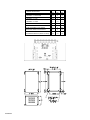
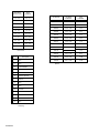
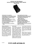
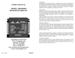
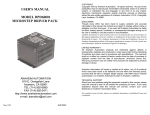
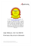
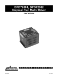
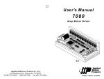
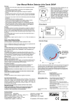
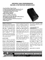
DPFHP001 HIGH PERFORMANCE
BILEVEL STEP MOTOR DRIVER PACK
• Very High Motor Power Output
• 15 Amperes/phase Maximum Operating Current
• 10 Amperes/phase Standstill motor current
• Internal Dual Voltage Power Supply
with 500VA Transformer
• High Start-Stop Speeds
• Transient Voltage Suppression
• Halfstep and Fullstep Operation
• Bilevel Drive Operation (No RFI or EMI problems)
• TTL/CMOS Compatible Inputs
• Clock and Direction or Dual Clock Operation
• Motor Turn-off Input
• +5VDC Output
GENERAL DESCRIPTION
The Anaheim Automation DPFHP001
Step Motor Driver Pack is designed for
motor applications that require very
high power output and high start-stop
step rates.
Outstanding motor
performance is achieved by means of
an enhanced bilevel or dual-voltage
drive technique. This Driver Pack
contains a high performance driver
board
(BLHP101),
a
500VA
transformer, and a dual power supply.
It may be used with six or eight lead,
size 34 and 42 step motors whose
phase current ratings range from 2 to
12.5 amperes per phase.
BILEVEL DRIVE
The basic function of a step motor
driver is to control the motor winding
currents.
Motor performance is
determined by how fast the driver can
increase and decrease the winding
currents. A rapid rise in winding current
is achieved by applying a high voltage
directly to a motor. This rapid rise of
current is also referred to as the "kick"
or operating current. When a desired
current level is reached, a low voltage
is applied to maintain a suitable holding
current level. When a motor winding is
DPFHP001 Driver Packs are shipped
#L010034a
turned off, a rapid decrease in winding
current is achieved by routing the
energy in the collapsing field back to
the power supply through a high
voltage path. The high voltage supply
furnishes the energy necessary to
maintain motor output torque at high
step rates thus providing high
mechanical power output. The low
voltage supply provides much of the
current needed at low step rates and all
of the holding current.
Bilevel drivers do not use high
frequency switching techniques as
chopper drivers do. Consequently,
they do not create the EMI, RFI, and
motor heating problems that are
associated with chopper drivers.
TRANSIENT VOLTAGE
SUPPRESSION
Transient Voltage Suppression (TVS)
Diodes on the motor phase outputs
allow for much longer motor cables to
be used. Normally when using long
motor cables, voltage transients and
spikes are created. These transients
often exceed the voltage ratings of the
output phase transistors, resulting in
blown transistors. The addition of the
from the factory with terminal 9
TVS Diodes suppresses these
transients and protects the transistors
against damage.
CLOCK AND DIRECTION/
CCW OPERATION
DPFHP001 Driver Packs are shipped
from the factory with terminals 6 and 5
assigned as CLOCK and DIRECTION
inputs respectively. Pulses applied to
the CLOCK input cause the motor to
step in the clockwise direction if the
DIRECTION input is at a logic "1" (or
no
connection),
or
in
the
counterclockwise direction if the
DIRECTION input is at a logic "0". By
setting JP1 to the "1-2" position,
terminal 5 becomes the CCW
(Counterclockwise
Clock)
input.
Pulses applied to the CCW input cause
the
motor
to
step
in
the
counterclockwise direction.
Either
positive or negative going pulses may
be used by setting JP3 to the
appropriate position. See Figure 1 and
Table 1 for Jumper locations and
settings.
MODE SELECT/+5V OUTPUT
assigned as an excitation Mode Select
separated from the motor
input. The Mode Select input is
connections. Wiring from the
used to select either halfstep orTABLE 1: Jumper Description.
X=DON'T CARE
driver to the motor should be
fullstep
motor
operation.
motor. Terminal 10 is the MOTOR
routed away from all other wiring.
Halfstep operation is generally
ON/OFF Input.
Hookup diagrams are shown in Figures
preferred because this mode provides
2 and 3.
better resolution, minimizes resonance
ADJUSTING THE KICK CURRENT
effects,
and
reduces
power
The kick (or operating) current level is
consumption. The motor steps in
CONNECTOR P1
the desired phase current level that the
increments of half the natural step
This 14-pin header type connector is
high voltage provides each time a step
angle, e.g. in 0.9 degree steps for a
used for a direct connection from the
is taken. The high voltage is turned off
1.8 degree step motor. In fullstep
DPFHP001 to Anaheim Automation
when this level is reached. The kick
operation, the motor steps in 1.8
Standalone Indexers such as the
current level should be set to
degree steps. By setting JP2 to the "1CL2541P. The DPFHP001 powers up
approximately 1.4 times the rated
2" position, terminal 9 becomes a
the indexer through the 14-pin cable
phase current. For example, a motor
+5VDC regulated output. The driver
and receives Clock, Direction, and
rated at 10 amps/phase should be
defaults to halfstep when the +5VDC
other signals from the indexer through
"kicked" to 14 amps. Table 2 shows
output is used.
the same cable. See Table 4.
various kick current levels for
corresponding phase currents. When
MOTOR ON/OFF INPUT
MOUNTING AND COOLING
using a motor listed in Table 3, use the
The MOTOR ON/OFF input can be
The DPFHP001 contains an internal
recommended potentiometer setting.
used to turn off all four motor phases
fan to create airflow through the unit.
WARNING: The kick current level must
(de-energize the motor) in applications
Heating considerations should include
be set before operating a motor.
where motor detent torque is sufficient
where the unit is mounted, the duty
MOTOR DRIVER CONNECTIONS
to maintain the load position. This
cycle
of
operation,
ambient
Motor wires are connected to the driver
feature can be used to reduce the load
temperature, etc. Care should be
pack through terminals 1, 2, 3, 12, 13,
on the power supply and the heat
taken so that no point on the chassis
and 14. Electrical connections to
dissipation in the driver circuitry and
exceeds 60 degrees Celsius.
control inputs should be kept physically
#L010034a
JUMPER DESCRIPTION
JP1
JP2
JP3
TERMINAL 5 = DIRECTION
2-3
X
X
TERMINAL 5 = CCW
1-2
X
X
TERMINAL 9 = HS/FS
X
2-3
X
TERMINAL 9 = +5VDC OUTPUT
X
1-2
X
POSITIVE GOING CLOCK INPUTS
X
X
2-3
NEGATIVE GOING CLOCK INPUTS
X
X
1-2
2-3
2-3
1-2
STANDARD PRODUCT (READY TO SHIP)
#L010034a
SPECIFICATIONS:
POWER REQUIREMENTS
105 VAC to 125 VAC for DPFHP001
210 VAC to 250 VAC for DPFHP001x220
CONTROL INPUTS
(Terminals 5,6,9,10):
Logic "0": 0 to 0.8 VDC.
Logic "1": 3.5 to 5 VDC.
CLOCK Input: (Terminal 6)
This input is either pulled down (for positive going pulses) or up (for negative going pulses) through a 10k ohm resistor ( set by
JP3). A pulse width of 15 microseconds minimum is required to step the motor. The maximum control pulse rate is limited by
motor performance.
DIRECTION/CCW Input: (Terminal 5)
When programmed as DIRECTION input (set by JP1), this input is internally pulled up to +5VDC through a 10k ohm resistor.
When a logic "1" (or no connection) is applied, the motor will step in the clockwise direction when pulses are applied to the
CLOCK input. Similarly, when a logic "0" is applied, the motor will step in the counterclockwise direction when pulses are
applied to the CLOCK input. When programmed as CCW input, the motor will step in the counterclockwise direction when
pulses are applied to this input (pulse requirement is same as for CLOCK input).
MODE SELECT/+5VDC OUTPUT: (Terminal 9)
When programmed as Mode Select Input (set by JP2), this terminal is internally pulled up to +5VDC through a 10k ohm
resistor. When a logic "1" (or no connection) is applied, the motor will operate in halfstep mode. When a logic "0" is applied,
the motor will operate in fullstep mode. When this terminal is programmed as +5VDC Output, up to 500mA may be used to
power up external circuitry. The driver defaults to halfstep when the +5VDC output is used.
MOTOR ON/OFF INPUT: (Terminal 10)
This terminal is internally pulled up to +5VDC through a 10k ohm resistor. When a logic "1" (or no connection) is applied, the
driver phase outputs are enabled and the motor is energized. When a logic "0" is applied, the driver phase outputs are disabled
and the motor is de-energized.
MOTOR PHASE OUTPUTS: (Terminals 1,2,13,14)
These outputs can sink a peak of 15 Amperes or sink 10 Amperes continuously and stand-off 250 VDC maximum.
MOTOR COMMON OUTPUTS: (Terminals 3,12)
These outputs can source a peak current of 15 Amperes, or source 10 Amperes continuously.
AMBIENT TEMPERATURE: 0 to 50 degrees Celsius.
SHIPPING WEIGHT: 15 pounds
#L010034a
Rated Motor
Phase Current
KICK
CURRENT
1.4 - 2.4
2.0 - 3.4
2.4 - 3.3
3.4 - 4.6
3.3 - 4.3
4.6 - 6.0
4.3 - 5.4
6.0 - 7.5
5.4 - 6.3
7.5 - 8.8
6.3 - 7.2
8.8 - 10.1
7.2 - 8.1
10.1 - 11.4
8.1 - 8.9
11.4 - 12.5
8.9 - 9.6
12.5 - 13.5
9.6 - 12.5
13.5 - 15.0
Table 2: Potentiometer Settings for
Kick Current.
P1 Pin
1
Description
N/C
2
N/C
3
+12V UNREG.
4
N/C
5
DIRECTION
6
MOTOR ON/OFF
7
HS/FS
8
N/C
9
N/C
10
CLOCK
11
0VDC
12
N/C
13
0VDC
14
N/C
TABLE 4: 14-Pin Header for Indexer
Interfacing.
#L010034a
AA MOTOR
HOLDING
CURRENT
KICK
CURRENT
34D106
1.95 - 3.00
4.20
34D109
3.12 - 4.80
6.72
34D207
2.28 - 3.50
4.90
34D209
3.00 - 4.60
6.44
34D213
4.23 - 6.50
9.10
34D307
2.28 - 3.50
4.90
34D311
3.58 - 5.50
7.70
34D314
4.55 - 7.00
9.80
42D112
3.97 - 6.10
8.54
42D119
6.18 - 9.50
13.3
42D212
3.97 - 6.10
8.54
42D219
5.98 - 9.20
12.88
42D225
8.25 - 10.00
15.00
TABLE 3 Holding Current and Kick Current Settings for AA
Motors.
TORQUE/SPEED CURVES
#L010034a