1
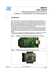
User Guide
STM32F107 LWIP Demos user guide
Introduction
STM32F107xx connectivity line microcontrollers feature a complete 10/100 Ethernet MAC
supporting MII and RMII with hardware support for the IEEE1588 precise time protocol,
enabling Ethernet connectivity for real-time applications.
The objective of this application note is to introduce the different demos included in the LWIP
TCP-IP package for the STM32F107_LK board.
In the first part you will find information on the hardware and software required, and how
to configure it.
The second part explains how to run these demos.
Note:
You will find additional information on LWIP package for STM32 in the Application note
AN3102 available here :
http://www.st.com/stonline/products/literature/an/16620.pdf
You will find the link to the STM3210C-EVAL LWIP demo firmware here :
http://www.st.com/stonline/products/support/micro/files/an3102.zip
STM32F107 LWIP Demos user guide
STM32F107 LWIP Demos user guide
Content
1
Introduction ...............................................................................................................3
1.1
1.2
1.3
1.4
2
What do you need ................................................................................................................ 3
How to configure the STM32F107 Learning Kit ................................................................... 4
Demo applications list........................................................................................................... 5
Modules per Demo ............................................................................................................... 5
Demos User Guide ...................................................................................................6
2.1
Simple Application ................................................................................................................ 7
How to compile and download the demos
7
How to run the simple demo
8
Using Wireshark to monitor the network traffic
8
Telnet Application................................................................................................................ 10
UDP-TCP Client/Server demos...........................................................................................11
2.3.1
UDP-TCP Client Demo
11
2.3.2
UDP-TCP Server Demo
12
Web Server Demo .............................................................................................................. 12
TFTP Demo ........................................................................................................................ 14
2.5.1
How to run the TFTP demo
14
2.5.2
How to use tftpd32 and wireshark software
14
2.1.1
2.1.2
2.1.3
2.2
2.3
2.4
2.5
2/16
STM32F107 LWIP Demos user guide
STM32F107 LWIP Demos user guide
1
Introduction
This first chapter gives an introduction on how to use the different demos provided. It
explains what are the hardware & software required, how to configure it. It also includes a
simple description of the different demos’ purpose and content .
1.1
What do you need
Here is the hardware required to run these demos :
- The STM32F107_LK Demo board (some demos require at least 2 boards)
- A JTAG debugger supported by IAR Workbench or RVMDK
- A 5V power supply
- An Ethernet cable to connect the board to your PC or to your Network
Note : the RS232 link to PC is not used in the current LwIP Package
Here are the softwares required
- IAR Workbench 5.x or RVMDK
- a TFTP Client (like tftpd32) available here : http://tftpd32.jounin.net/
- a Network analyzer (like WireShark) available here : http://www.wireshark.org/
3/16
STM32F107 LWIP Demos user guide
STM32F107 LWIP Demos user guide
1.2
How to configure the STM32F107 Learning Kit
Here is the required configuration of the demoboard :
JP1 & JP2 set to UserFlash position (0-X or jumper position 2-3)
JP3 & JP4 set
JP5 & JP6 set to Ethernet position (jumper position 2-3)
On the back of the demoboard, MII must be selected. To do so you need to solder the 3
“jumpers” on the lower right side.
4/16
STM32F107 LWIP Demos user guide
STM32F107 LWIP Demos user guide
1.3
Demo applications list
Demo
Simple Demo
Telnet Demo
UDP-TCP Client Demo
Description
The TCP-IP Stack without application modules
A simple helloword application using the Telnet protocol
A set of 2 demos to be loaded on different boards:
- at least one client
- one server.
UDP-TCP Server Demo
UDP & TCP Packets are exchanged between the 2 boards,
to control some LED.
A simple webpage hosted in the demoboard is displayed in
your browser
A TFTP demo to get files from the demo board or put file
into an SD card inserted in the board card reader
Web Server demo
TFTP Demo
1.4
Modules per Demo
The LWIP TCP-IP stack already contains many modules, not all the modules provided
are used in each demos. The table below shows which modules are compiled (or not) in
each example.
DNS
TFTP Demo
Telnet Demo
UDP-TCP
Server
UDP-TCP
Client
DHCP
WebServer
Application
Ping
TFTP Demo
TCP
Web server Demo
UDP
UDP-TCP Server
ICMP
UDP-TCP Client
Demos Application
IP
Telnet Demo
Application
Modules
ARP
Simple Demo
EFSL (file system)
Demo Name
TCP – IP Key Modules
5/16
STM32F107 LWIP Demos user guide
STM32F107 LWIP Demos user guide
2
Demos User Guide
The LWIP package for STM32F107xx connectivity line microcontrollers comes with a rich
set of demos
A simple application implementing the LwIPTCP-IP stack, DHCP Client and PING
application. once the STM32F107_LK board is connected to a DHCP server it gets its IP
address and displays it on the LCD. the Ping application is available to check that the
STM32F107_LK board is responding to ping requests.
A simple Telnet demo allow the PC to open a telnet connection with the board. This
example is a simple “Helloword over telnet” kind of application
UDP/TCP Client/Server: this is a simple example based on a minimum of two
STM32F107_LK Boards. One board is Server and all others are Clients. It provides
source code examples for UDP and TCP connections.
Webserver Demo : it displays an html page once the STM32F107_LK board IP address
(given by the DHCP) is typed in the web browser. This introduction page includes a
presentation of the embedded protocols in LWIP. Another page shows a status bar
displaying instantaneously the potentiometer (RV1) analog input conversion (available on
STM32F107_LK board). The user can modify the potentiometer position and the status
bar shape is updated accordingly. Another LED control page allows the user to turn
ON/OFF the LEDs of the board.
TFTP Server : this lets the user PUT and GET files from the remote PC (client) to the
STM32F107_LK board (Server). The files are read from (or written into) the SD Card
inserted in the SD Card reader of the STM32F107 board.
6/16
STM32F107 LWIP Demos user guide
STM32F107 LWIP Demos user guide
2.1
Simple Application
This simple example provides an application template, see below the procedure to run
this example.
In this example, the board is connected on a network with a DHCP server, it
automatically get this IP address. You may PING the board from your PC to check it is
properly connected on the network.
2.1.1 How to compile and download the demos
Once you opened the project with your IDE (IAR workbench or Keil ) follow the steps
describes in the screen capture below to compile and run the demo.
For IAR Workbench users :
For Keil RVMDK users
7/16
STM32F107 LWIP Demos user guide
STM32F107 LWIP Demos user guide
Note :
The IAR projects are build using IAR Embedded Workbench version 5.4. If these
workspaces are opened with older version of IAR Embedded Workbench, an error
message will be displayed and some of the project configuration will be lost.
One way to overcome this incompatibility is to get the newest version of IAR Embedded
Workbench and open the project. Then you can use this new version of IAR, or recopy
the project settings and complete the part of the configuration that was lost in your older
IDE.
2.1.2 How to run the simple demo
When running this demo on a network with a DHCP server you should see the following :
Then you will be able to send a Ping command to the board.
2.1.3 Using Wireshark to monitor the network traffic
Wireshark Network analyzer is a freeware that allows you to see the packets exchanged
between the PC and the Board.
To do so, you need to run Wireshark and in the menu Capture\Interfaces… select the
network interface you want to log
8/16
STM32F107 LWIP Demos user guide
STM32F107 LWIP Demos user guide
Make sure to use the appropriate filter to display only the relevant part of the network
traffic. Then you will get the following log.
In the Screen capture below you will find :
- an IP address filter : ip.host==192.168.1.2
- the packets sent or received by this IP address for a PING command
- The details of one frame
Note : Wireshark can only monitor the traffic sent or received by the PC, you won’t be
able to monitor the traffic between 2 boards.
9/16
STM32F107 LWIP Demos user guide
STM32F107 LWIP Demos user guide
2.2
Telnet Application
(follow the procedure described in the Simple Application chapter on how to start the
application.)
This demo implement a simple telnet application. Once the telnet connection is open
between the PC and the Board, a simple “helloword” communication takes place.
To run this demo you need to open a telnet connections as follow :
1) You can first check the connection between your PC and the board using a PING
command, once done you can run the Microsoft telnet client from the command line
window using the command “telnet
2) Then you need to connect the client to the board, by using the command “open
x.x.x.x” where “x.x.x.x” is the IP address of the board.
3) Then you should see the following “Helloword” communication :
10/16
STM32F107 LWIP Demos user guide
STM32F107 LWIP Demos user guide
2.3
UDP-TCP Client/Server demos
Theses demos implement a simple client/server communication protocol (data exchange,
1 byte data length). One server board and one or more client boards are required to run
this example. Both can be directly connected with a crossover cable or plugged to a
network with straight cables.
If a DHCP server is available, both boards get dynamic IP addresses. Once connected to
the server, the board sends a TCP frame with 1 bytes of data on an opened connection
asking to set/reset the LED1 when the Key B3 is pressed. If the Key B2 is pressed, the
application sends a TCP frame with 1 bytes of data on an opened connection asking to
set/reset the LED2.
Depending on the byte value, it requests the Server application to set or reset the
corresponding LED.
2.3.1 UDP-TCP Client Demo
(follow the procedure described in the Simple Application chapter on how to start the
application.)
This demo requires having one other board configured as a server. Make sure that your
starts the server board firsts, then the client board.
Once the 2 boards are connected you should see the following :
The c: x.x.x.x is the client IP address, in this
example 192.168.1.4 is the board IP address
Once connected to the server, s: x.x.x.x will
be displayed on the screen giving the
server’s IP address. In this example,
192.168.1.2 is the IP address of the remote
server.
Once you see this screen you are able to
control the server’s LEDs using the 2 buttons
of the board :
Here is the detailed communication flow between the client and server
Part 1 : UDP Transfer
- The server listen for UDP Data on a dedicated port (0x7 in this demo)
- The client broadcasts a UDP Packet on the network on the same port
- The server answers a UDP Packet to the client on a different port (0x4 in this demo)
Now both the client and the server know each other’s IP address
Part 2 : TCP Transfer
- The server listen for TCP Data on a dedicated port (0x4 in this demo)
- Now that the client knows the server’s IP address, it setup a TCP connection on this
port
- Each time a is pressed, the client send a simple TCP packet to the server to turn on
or off the LED
NOTE : It is mandatory to first run the server board and then turn on the client board,
otherwise the boards may not find each others.
11/16
STM32F107 LWIP Demos user guide
STM32F107 LWIP Demos user guide
2.3.2 UDP-TCP Server Demo
(follow the procedure described in the Simple Application chapter on how to start the
application.)
This demo requires to have at least one other board configured as a client. Make sure
that your starts the server board firsts, then the client board.
Once connected you should see the following :
The s: x.x.x.x is the server IP address, in this example
192.168.1.2 is the board IP address
Once connected to the client, c: x.x.x.x will be displayed
on the screen giving the client’s IP address. In this
example, 192.168.1.4 is the IP address of the remote
client.
Once you see this screen the server’s depending on
the TCP packets received from the client.
The workflow is the same as the one described in the client demo example.
2.4
Web Server Demo
(follow the procedure described in the Simple Application chapter on how to start the
application.)
In this demo, a simple webserver application is loaded into the board and accessed using
your webbrowser.
In this example, the board and the computer are connected on the same network, each of
the devices getting its IP address from the DHCP server.
12/16
STM32F107 LWIP Demos user guide
STM32F107 LWIP Demos user guide
Clicking the led control link will bring you to a simple form allowing you to control the LED
on the board. Please note that only 3 LEDs are available on the STM32F107_LK.
The ADC input displayed on the webpage is controlled by the potentiometer on the lower
left corner of the STM32F107_LK demo board.
13/16
STM32F107 LWIP Demos user guide
STM32F107 LWIP Demos user guide
2.5
TFTP Demo
2.5.1 How to run the TFTP demo
Follow the procedure described in the Simple Application chapter on how to start the
application, load the TFTP project in the STM32F107_LK board and run it.
In this example, the server is the demo board and the PC is the client :
- the GET command of the Client (the PC) will request a file from the server and
transfer it from the board to the PC
- the PUT command of the Client (the PC) will send a file to the server transfering it
from the PC to the board
In this example, the files transferred from the PC to the board are stored in the SD card
connected on the STM32F107_LK. So you need to make sure that a properly formatted
SD Card is inserted into the card reader :
2.5.2 How to use tftpd32 and wireshark software
The following example, tftpd32 is used as a tftp client on the PC. Here is the interface
14/16
STM32F107 LWIP Demos user guide
STM32F107 LWIP Demos user guide
WireShark is also used to see the TFTP packets exchanged between the PC and the
board. Here is a PUT Tranfer
Once the PUT transfer is completed, you can see that the file PC2LK was copied in the
SD card .
15/16
STM32F107 LWIP Demos user guide
STM32F107 LWIP Demos user guide
Now that there is one file into the SD Card, I can perform a GET operation to copy it back
to the PC . Here is a GET transfer
16/16
STM32F107 LWIP Demos user guide