1
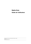
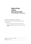
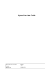
Thermo-Tuff
User Guide
To re-order quote part number:
HD0476
Revision:
1.0.1
Revision Date:
January 2011
1 Introduction
The Hydronix Thermo-Tuff is a fast response, linear, high precision temperature sensor for use in industrial
processes, including measurement in bulk materials and mixing applications. It is especially suited to high wear
environments.
1.1
Part numbers and Accessories
Part No
1.2
Description
TT01
Thermo-Tuff sensor
0310
Mounting Collar
0320
Extension Mounting Sleeve and Collar
Safety
For continued safe operation, this product should only be used for temperature measurement in a process
control system and should be installed and operated as described in this document.
The cable screen must be connected to the system earth.
1.3
Specifications
Measurement Range:
Storage Temperature:
Voltage Range:
IP Rating:
Weight:
Installed T90
0 - 80°C
-10 - 80°C
10 - 28v DC
(Reverse Polarity Protected)
IP68
600g including 4m cable
56s
2 Mechanical Installation
2.1
Dimensions
115mm
Ø24mm
Sensing
Surface
21mm
A/F
2.2
4m
Installation Options
The sensor can be mounted vertically or horizontally. The sensing surface must touch the material being
measured.
The Thermo-Tuff is designed to be maintenance free and does not require calibration.
2.2.1
Installing using the Mounting Collar
Drill a 25mm diameter hole in the mounting surface and
weld the Mounting Collar centrally over it. The ThermoTuff is retained by tightening two bolts on to the long flat
areas of the sensor.
Ø25mm
Hole
To remove the sensor, loosen the screws and withdraw
from the Mounting Collar. A spanner can be used on the
two flat areas of the sensor to ease extraction of the
sensor from the Mounting Collar.
3-40mm
Mounting
Surface
Weld
Flats to
ease
removal
2x
retaining
bolts at
90°
2.2.2
When flush mounted, it is important to adjust the position
of the sensor periodically so that the sensing face
remains flush with the mounting surface and does not
become damaged by any moving parts within the system.
This will also prevent the build up of material around the
sensor.
Installing using the Extension Mounting Sleeve and Collar
When mounting in a bin or hopper, the Extension
Extension Mounting
Collar
Holes for inserting an extension
Mounting Collar is welded into a 43mm diameter
bar to ease removal
Extension Mounting Sleeve
220mm
hole. The sensor should be installed into the
Extension Mounting Sleeve so that it is flush with
the end of the sleeve. It is retained with two grub
screws. The Sleeve is then fitted in the Mounting
Collar and the retaining bolts used to secure the
assembly.
Weld
Ø43mm
Hole
150mm
Max
2x Retaining
Bolts @ 90°
50mm
3 Electrical Installation
3.1
Power
The Thermo-Tuff is designed to be powered by the 4-20mA current loop. It does not have connections for an
external power supply.
Analogue Output
The Thermo-Tuff outputs a continuous 4-20mA signal and this is scaled to read between 0 and 80°C as shown:
Temperature in °C = (Io - 4) x 5
Where Io is the output current in mA.
Current Output
90
Temperature
4mA
0 °C
32 °F
20mA
80 °C
176 °F
Temperature (°C)
3.2
80
70
60
50
40
30
20
10
0
0
5
10
Current Output (m A)
15
20
3.3
Connections
The Thermo-Tuff is supplied with a 4 metre unterminated cable. The wire colours are:
Wire Colour
Description
Red
Current Loop Positive
Blue
Current Loop Negative
Screen
Earth
When installing the Thermo-Tuff a drip loop should be used to protect the cable gland from any water ingress.
The Thermo-Tuff cable screen must be connected to a good system earth point.
3.4
Output Circuit Design
The output circuit should be designed such that VA is
between 10v and 28v DC. This can be checked by
calculating the following:
Thermo-Tuff
+
VA
Power +
Supply -
VPSU
+ Control System
Input
-
VA = VPSU - (I*R)
Where I is 4mA for the maximum VA and 20mA for the
minimum VA. R is the total resistance of the circuit
including the cable.
4 Troubleshooting
Inaccurate Temperature
Noisy Signal
No Current
Output clamps at less than 20mA
Check the PLC input scaling
Check the voltage across the TT01.
Check total resistance in the loop.
Check polarity
Check the resistance of the cable and the control system input.
Check the voltage across TT01
5 Declaration of conformity
This device complies with part 18 of the FCC Rules.
This device is designed and manufactured in
accordance with the following directives:
2004/108/EC
The Electromagnetic Compatibility
Directive and its amending directives
© 2011 Hydronix Ltd
7 Riverside Business Centre, Walnut Tree Close, Guildford, Surrey, GU1 4UG, UK
Local regulations regarding the
disposal or recycling of waste
electronic equipment must be
followed.