1
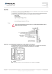
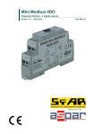
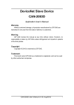
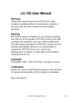
USER GUIDE
PEL 8K / PEL 8K-M
V2.0.0 (24.10.2014)
1 (7)
COMMISSIONING
Mounting
- The transmitter should be installed above the measuring point to avoid condensation problems.
- The duct overpressure is detected by connecting the measuring point to + connector and by leaving
the - connection open (surrounding space pressure). Accordingly, the duct under-pressure is detected by
connecting the measuring point to - connector and by leaving the + connection open.
- Install the measuring hoses carefully so that the hoses don't bend too tightly. Too tight curves may prevent the
air flow to the sensor.
- The hose length doesn't effect on the measuring accuracy. However, long hoses generate delay on the
measurement.
Wiring
Device wiring and commissioning can only be carried out by qualified professionals. Always make the
wirings while the power is switched off.
USER GUIDE
PEL 8K / PEL 8K-M
2 (7)
Selecting the measuring range
The measuring range can be selected with the jumpers S2, S3 and S4.
A. Pressure selection jumpers
0…1000
0…1500
0…2000
0…2500
0…3000
0…4000
0…5000
0…8000 *)
S2
S3
S4
*)
Factory setting. The 0…8000 Pa range is also used for the custom range setting.
The custom range is 0…8000 Pa as a default. The range can be changed by using ML-SER tool or by defining the
high limit to the Modbus register 40002 (the low limit is 0 Pa).
Selecting the time constant
The time constant can be selected with the jumper S1.
A. Time constant selection jumper
2s
8 s*)
S1
*)
Factory setting.
Selecting the output mode
The transmitter output can be either pressure linear or flow linear. The output mode can be selected with the jumper
S5.
A. Output mode selection jumper
pressure linear*)
S5
*)
Factory setting.
flow linear
USER GUIDE
PEL 8K / PEL 8K-M
3 (7)
Flow linear output
When the flow linear output is selected, the transmitter outputs are converted to follow the flow across the
measurement area. The conversion is made by using square root extraction method.
See the following figure for the output example in the 0…1000 Pa range:
=
Pressure linear output
=
Flow linear output
ZERO POINT CALIBRATION
The purpose of the zero point calibration is to remove the possible long term drift. The zero point is calibrated
automatically every five minutes.
NOTE: The zero point calibration is also executed on the start-up and a minute after the start-up.
ML-SER TOOL
With the ML-SER tool you can change the device settings, Modbus settings for example.
Connecting ML-SER tool to the device
1.
Remove the cover.
2.
Disconnect the display cable (N models).
3.
Connect the ML-SER tool cable to the display connector.
A. Display connector
When the ML-SER is successfully connected, the pressure measurement value is displayed on the ML-SER
tool display. The connecting can take few seconds.
USER GUIDE
PEL 8K / PEL 8K-M
4 (7)
ML-SER menu
The device settings can be changed by using ML-SER tool. You can proceed in the menu by pressing the M and OK
buttons. The values can be changed with the ”+” and ”-” buttons. The value is accepted with the OK button. The
settings are saved when exiting the menu. The following menu structure contains the factory settings.
The Modbus and analogue outputs are disabled when entering the menu for the measuring mode. In addition the
analogue outputs maintain the same voltage, as they were before entering the menu.
Communications menu (M models only)
The Modbus settings can be changed through the COMMUNICATIONS menu.
USER GUIDE
PEL 8K / PEL 8K-M
5 (7)
Custom range menu
The CUSTOM RANGE menu is for setting the custom pressure range high limit. The custom range is in use when all
the pressure range selection jumpers are placed.
Output menu
You can change the measurement output scales through the OUTPUT menu.
Info menu
The INFO menu can be used for checking the software version and resetting to the factory settings.
Resetting to the factory settings
1.
Press the “-“ button for five seconds in the software version display.
2.
Change the resetting dialog answer to “yes”.
3.
Press OK button.
The factory settings are now reset.
USER GUIDE
PEL 8K / PEL 8K-M
6 (7)
MODBUS
Bus properties
Protocol
RS-485 Modbus RTU
Bus speed
9600/19200/38400/57600 bit/s
Data bits
8
Parity
none/odd/even
Stop bits
1
Network size
up to 127 devices per segment
NOTE: The memory durability is 10000 write cycles.
Bus termination
The Modbus can be terminated by placing the Modbus termination jumper.
A. Modbus termination jumper
Supported Modbus functions
0x01
Read Coils
0x02
Read Discrete Inputs
0x03
Read Holding Registers
0x04
Read Input Registers
0x05
Write Single Coil
0x06
Write Single Register
0x0F
Write Multiple Coils
0x10
Write Multiple Registers
0x17
Read/Write Multiple Registers
USER GUIDE
PEL 8K / PEL 8K-M
7 (7)
Modbus registers
Data type:
bit
unsigned
signed
= 0 or 1
= unsigned integer (0…65535)
= integer (-32768…32767)
Input registers (read only)
Register
Parameter description
30001
Pressure measurement
30002
Time constant
30003
Selected pressure range
30004
Measurement output
*)
Data type
signed
Value
Range
-32768…32768
-32768…32768 Pa
unsigned
0…60
0…60 s
unsigned
0…7
0=
1=
2=
3=
4=
5=
6=
7=
0…1000
0…100,0 %
signed
0…1000 Pa
0…1500 Pa
0…2000 Pa
0…2500 Pa
0…3000 Pa
0…4000 Pa
0…5000 Pa
0…8000 Pa /
custom *)
The custom range is 0…8000 Pa as a default. The range can be changed by using ML-SER tool or by defining the high limit to the
Modbus register 40002 (the low limit is 0 Pa).
Holding registers (read / write)
Register
Parameter description
40001
Not in use
Data type
signed
Value
Range
Default
-
-
0
40002
Custom scale high limit
signed
1…80
100…8000 Pa
80
40003
Voltage output scale
unsigned
0-1-2
0 = 0…10 V
1 = 2…10 V
2 = 0…5 V
0
40004
Current output scale
unsigned
0-1
0 = 4…20 mA
1 = 0…20 mA
0