1
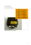
Software Manual—RS232
Laser Merge Module
Document # SU-256521-09 Rev A
The information presented in this document is proprietary to
Spectral Applied Research Inc. and cannot be used for any
purpose other than that for which it is intended.
10 North Rivermede Road
Concord, Ontario, CANADA L4K 2H2
www.SpectralAppliedResearch.com
Software Manual—RS232
Laser Merge Module
Document # SU-586521-09 Rev A
Table of Contents
1. INTRODUCTION .................................................................................1
2. CONTROLS .........................................................................................1
2.1
2.2
2.3
2.4
2.5
Shutters .............................................................................................................................. 1
Neutral Density Filters ..................................................................................................... 1
Power Monitor .................................................................................................................. 2
Microcontroller Interfaces ............................................................................................... 2
RS-232 Interface................................................................................................................ 2
3. RS232 PROTOCOLS ...........................................................................2
3.1 Control Commands........................................................................................................... 2
3.1.1 Command: Shutter Control ..................................................................................... 3
3.1.2 Command: Shutter Status........................................................................................ 3
3.1.3 Command: Change Transmission ........................................................................... 3
3.1.4 Command: Read Transmission ............................................................................... 4
3.1.5 Command: Get Laser Line Setup............................................................................ 4
3.1.6 Command: Read Power Monitor ............................................................................ 5
3.2 Trigger Commands........................................................................................................... 5
3.2.1 Exposure Configure .................................................................................................. 5
3.2.2 Trigger In Configure ................................................................................................ 5
3.2.3 Trigger Out Configure ............................................................................................. 6
3.2.4 Read Trigger In Configuration................................................................................ 7
3.2.5 Read Trigger Out Configuration............................................................................. 7
3.2.6 Read Exposure Configuration ................................................................................. 7
3.3 Other Commands.............................................................................................................. 7
3.3.1 Home Motor .............................................................................................................. 7
4. TRIGGER IMPLEMENTATION GUIDE ................................................8
4.1 Auxiliary connector .......................................................................................................... 8
4.2 Programmable TTL.......................................................................................................... 8
4.2.1 Trigger In................................................................................................................... 8
4.2.2 Trigger Out................................................................................................................ 9
4.2.3 Trigger Flow Charts ............................................................................................... 10
4.2.4 Programming........................................................................................................... 15
List of Figures
Figure 1: Trigger In, Cycle driven flow charts ........................................................................ 10
Figure 2: Trigger In, State driven flowcharts .......................................................................... 12
Figure 3: Trigger Out flowchart................................................................................................ 14
i
The information presented in this document is proprietary to Spectral Applied Research Inc. and
cannot be used for any purpose other than that for which it is intended.
Software Manual—RS232
Laser Merge Module, model LMM5
Document # SU-586521-01 Rev A
1. INTRODUCTION
This manual is a compilation of material on the programming of the Laser Merge Module, model
LMM5 using the RS-232C interfaces, and the triggering capability available via TTL and
dedicated BNC connectors on the control unit. The document is presented in major segments
starting with a description of the pertinent controls.
2. CONTROLS
The LMM5 can be controlled either manually or by a computer via a RS-232 or TTL interfaces.
The following is a compilation of the programmable controls and a brief description of their
function. All references to controls and indicators are highlighted in bold in the descriptions
below. The following figures show the front and rear panels of the control unit.
2.1 Shutters
Mechanical shutters are built into the LMM5. A shutter is installed for each laser at the exit
from the laser compartment. A master shutter is also installed prior to the exit from the head
unit. The laser shutters are controlled by lighted momentary pushbutton switches located on the
front panel of the control unit or by the computer. The pushbuttons are identified by the label
Laser Select and by the laser position number (1-5). The light is red when the shutter is open.
No light is showing when the shutter is closed. Pushing the pushbutton will toggle the status of
the shutter.
The master shutter is initialised open about 5 seconds after power is applied by the Master Key
switch and its indicator turns red. Any other shutter can now be selected as required. The
Master Shutter pushbutton controls the master shutter in the same manner as the other shutters.
If the Remote Interlock is open circuited, then all the shutters close immediately.
2.2 Neutral Density Filters
Neutral density filter wheels are installed for each laser in order to provide intensity control. The
manual controls for these mechanisms are located on the control unit. The controls consist of a
three-position momentary toggle switch labelled Intensity Adjust to select increasing or
decreasing intensity direction, or off. The toggle switch is held to continue the motion in the
selected direction. It will stop when either the minimum or maximum point has been reached. A
particular filter wheel is selected by opening the associated shutter. If more than one shutter is
open, the filter wheel associated with the last one opened may be driven. A green indicator is
provided for each filter wheel so that the operator can readily confirm which wheel is selected.
The indicators are identified by the label Intensity Select and by the laser position number (1-5).
When a filter wheel is selected and the momentary toggle switch pushed for increasing or
decreasing intensity, the speed of the wheel starts off slow but increases if the switch is held in
place. The wheel takes about 10 seconds to change from maximum to minimum or vice versa.
1
Software Manual—RS232
Laser Merge Module, model LMM5
Document # SU-586521-01 Rev A
2.3 Power Monitor
The LMM5 contains a built-in power monitor on the front panel of the head unit. An input
connector is provided to accept the fiber cable connected to the LMM5 output. A BNC
connector is provided to allow measurement of the DC voltage produced by the LMM5 output.
The power monitor consists of a photodiode with neutral density filter and a resistive load. Thus,
the current produced by the photodiode is converted to a voltage. This can be measured by a
voltmeter attached to the power monitor output connector or via an analog-to-digital converter
by the computer.
2.4 Microcontroller Interfaces
Two BNC connectors are provided on the rear panel of the control unit. Both are used to
coordinate the LMM5 with other experimental apparatus. The Trigger In is used to control the
on/off cycle for laser illumination based on externally generated conditions. A set of exposure
states is defined and the trigger steps through these states in order. The Trigger Out can be set in
two modes, clock driven or state driven. For state driven, a TTL pulse will be sent every time
the exposure state is changed. For clock driven, a TTL pulse is sent out at a regularly interval.
2.5 RS-232 Interface
A 9-pin D subminiature connector (female), labelled Serial, is provided on the rear panel of the
control unit to allow serial communication with the microcontoller. The arrangement is a
standard DTE to DCE configuration and requires a straight cable to connect the control unit to a
computer. The pin-out of this connector is as follows: pin 2--Rx from DTE; pin 3—Tx to DTE;
pin 5—ground.
3. RS232 PROTOCOLS
3.1 Control Commands
For further information contact David Cooper at [email protected] or 905.326.5040 x405
Command structure: The command structures listed in this document use binary values to issue
the commands. However many serial communication programs prefer to send ASCII data.
Therefore to send one binary byte the control software should always send the equivalent
hexadecimal value in ASCII representation. This requires sending two bytes for every single byte
of binary data. Any command sent to the controller should terminate with a carriage return
(ASCII value 13). For example, to send the binary sequence 0x1A,0xFF,0x00,Ox12 – the serial
program should send the ascii string “1AFF0012<CR>” – or in ASCII values:
49,65,70,70,48,48,49,50,13
Serial settings are 19,200 bps, no flow control, one stop bit, no parity, 8 data bits
2
Software Manual—RS232
Laser Merge Module, model LMM5
Document # SU-586521-01 Rev A
3.1.1
Command: Shutter Control
Set the open/closed states of the shutters
Op Code: 0x01
Data: 1 byte representing bit field for states of up to 8 shutters, “1” indicates shutter open and
“0” means shutter closed.
Return: One Ack byte is sent as 0x01 and indicates that the command was processed and 0xFF
if there is any error
Example:
Send: 0x01 0x02 – opens shutter 2 and closes all others
Receive: 0x01 – operation is acknowledged
Send: 0x01 0x09 – opens shutter 4 and 1 and closes all others
Receive: 0x01
Notes: Shutters take 1-2 milliseconds to open so this command does not wait to see if shutters
are set successfully before acknowledging. Use the shutter status command to verify shutter
states.
3.1.2
Command: Shutter Status
Read the open/closed states of the shutters
Op Code: 0x02
Data: None
Return: 2 bytes. First byte is an Ack byte, 0x02. Second byte gives shutter states in a bit field as
in shutter control.
Example:
Send: 0x02
Receive: 0x02 0x02 – shutter 2 is open, all others are closed
Send: 0x02
Receive: 0x02 0x09 – shutter 1 and 4 are open, all others closed
Notes: This command returns the status of the photodetector sensor on each shutter. It takes 1 – 2
milliseconds for this sensor to respond to a shutter operation.
3.1.3
Command: Change Transmission
Set the Transmission of a specific laser line. This may be done through a filter wheel or an
AOTF.
Op Code: 0x04
3
Software Manual—RS232
Laser Merge Module, model LMM5
Document # SU-586521-01 Rev A
Data: 3 bytes. First specifies the lines to change attenuation (line 1 is 0x00). Second and third
give transmission from 0 to 1000 (0 is minimum transmission and 1000 is maximum). Byte order
is big endian (high byte first).
Return: 1 byte Ack 0x04 normally and 0xFF if there is an error. An error could occur if the
device loses its position for the filter wheel or fails to set the voltage to an AOTF. When
controlling a filter wheel, this command may take several seconds to acknowledge as it waits
until the wheel movement is complete before acknowledging.
Example:
Send: 0x04 0x03 0x02 0xBC – sets the transmission to 700 (70.0%) on line 4. 0x02 is high byte
(equals 512) and 0xBC is low byte (equals 188 so 512+188=700).
Receive: 0x04 – Ack
Notes: Transmission is logarithmic for a filter wheel. For our 20dB wheels 50% = 10dB and is
actually 10% transmission. When the device with filter wheels is first turned on, the filter wheels
automatically rotate to find the home sensor and then return to their position at initial power up.
The AOTF (if applicable) is set to minimum transmission at startup.
3.1.4
Command: Read Transmission
Read the current transmission setting for a specific laser line. This may be done for a filter wheel
or an AOTF.
Op Code: 0x05
Data: 1 byte to indicate which line to return
Return: 3 bytes. First is an ack 0x05 for normal operation and 0xFF for error. Next two bytes
give transmission from 0 to 1000 in big endian format as in change transmission command.
Example:
Send: 0x05 0x03 – read transmission of line 4
Receive: 0x05 0x02 0xBC – transmission is 700
3.1.5
Command: Get Laser Line Setup
Read which laser line wavelength is installed in which slot.
Op Code: 0x08
Data: None
Return: 17 bytes. First is an Ack 0x08 for normal operation and 0xFF for error. Each two bytes
after gives the wavelength of the laser in the corresponding line for a total of 8 lines. The byte
order is big endian (high byte first). The wavelength is in angstroms so 4610 corresponds to
461.0 nm. A value of zero indicates that no laser line is assigned to that slot.
Example:
Send: 0x08
4
Software Manual—RS232
Laser Merge Module, model LMM5
Document # SU-586521-01 Rev A
Receive: 0x08 0x15 0xEA 0x13 0x2E 0x11 0x30 0x00 0x00 0x00 0x00 0x00 0x00 0x00 0x00
0x00 0x00 – line 1 is 561 nm, line 2 is 491 nm, line 3 is 440 nm and lines 4-8 are not available.
3.1.6
Command: Read Power Monitor
Read the voltage on the power monitor photodiode
Op Code: 0x0A
Notes: not currently available with rs232 control. Future versions will have this capability.
3.2 Trigger Commands
These commands define the function of the trigger in and out BNCs from the control box.
Contact Spectral Applied Research for more information on trigger controls.
3.2.1
Exposure Configure
Op-Code: 0x21 (33)
Bytes Sent: 1+3M (1<=M<=20)
Bytes:
1: # of exposure states (value of 1 to M)
2 to (M+1): exposure states
(M+2) to (3M+1): exposure time
Description: This command defines the exposure parameters that the unit cycles through upon
receiving a trigger in. The number of exposure states determines the number of different shutter
states that the unit will go through before repeating the cycle. The exposure states give the
shutter states for each exposure in the cycle. The format is the same as the shutter control
command so each bit in the byte indicates the state of the corresponding shutter. The exposure
time gives a series of unsigned 2-byte integers that define the exposure time of each state. The
exposure time is in 0.1 msec increments for a maximum of a bit more than 6.5 seconds. The
behaviour of the exposure time depends on the trigger in mode (see below). In Step mode, the
exposure time defines how long the shutter stays open before reverting to an all closed state. In
Cycle mode, the exposure determines how long to wait before moving to the next state.
Example:
0x21;0x02;0x17;0x06;0x10;0x00;0x03;0xAD: Defines two exposure states- shutter 1 and 5 open
then shutter 2 and 3 open with exposure times of 0.4096sec and 0.0941sec respectively.
3.2.2
Trigger In Configure
Op-Code: 0x22 (34)
Bytes Sent: 3
5
Software Manual—RS232
Laser Merge Module, model LMM5
Document # SU-586521-01 Rev A
Bytes:
1: Enable(1)/Disable(0) Trigger In
2: # of trigger input before action
3: Define step(0) or cycle(1) trigger
Description: This command enables or disables the trigger in input and defines the trigger
behaviour. Send 0 in the first byte to disable the trigger in and 1 to enable it. Step trigger is
defined by a 0 in the third byte and Cycle mode by a 1. See trigger documentation for behaviour
of each mode. The number of trigger inputs before action determines the number of trigger
inputs to receive before taking action such as starting a state sequence or moving to the next
state.
Example:
0x22;0x01;0x02;0x00: Enables a Step trigger and requires two trigger in events for each step.
Notes: Trigger In is positive edge TTL. There is a jitter of up to 50 microseconds in processing
the trigger in. Motor control function and shutter control (manual and usb) are disabled while
trigger is active. Motor control is deactivated due to limited timing resources and speed of the
MCU and shutter control is deactivated since shutter states are determined by the exposure
configuration.
3.2.3
Trigger Out Configure
Op-Code: 0x23 (35)
Bytes Sent: 4
Bytes:
1: Enable(1)/Disable(0) Trigger Out
2: State(0)/Clock(1) driven mode
3-4: Exposure Time
Description: This commands enables the hardware trigger out. The trigger out can either be state
driven so a trigger out occurs every time the shutter changes exposure state, or clock driven with
the period between trigger outs is determined by exposure time. For state driven, the exposure
time determines the delay from the state change to the trigger out. The exposure time is in 0.1
msec increments with a maximum of a bit more than 6.5 sec. The trigger out is a TTL pulse with
a width of a few microseconds.
Example:
0x23;0x01;0x00;0x03;0xAD: Define a state driven trigger out with a delay of 0.0941 sec
0x23;0x01;0x01;0x00;0xC8: Define a clock driven trigger out at 50 Hz (20 msec delay)
Notes: Motor movement is disabled when trigger out is active
6
Software Manual—RS232
Laser Merge Module, model LMM5
Document # SU-586521-01 Rev A
3.2.4
Read Trigger In Configuration
Op-Code: 0x25 (37)
Bytes Sent: None
Return: Returns the state of the trigger in setup in the same format as the trigger in configuration
command
Example:
Send 0x25
Receive 0x25;0x01;0x02;0x00
3.2.5
Read Trigger Out Configuration
Op-Code: 0x26 (38)
Bytes Sent: None
Return: Returns the state of the trigger out setup in the same format as the trigger out
configuration command
Example:
Send 0x26
Receive 0x26;0x01;0x00;0x03;0xAD:
3.2.6
Read Exposure Configuration
Op-Code: 0x27 (39)
Bytes Sent: None
Return: Returns the exposure parameters in the same format as the exposure configuration
command
Example:
Send: 0x27
Receive: 0x27;0x02;0x17;0x06;0x10;0x00;0x03;0xAD
3.3 Other Commands
3.3.1
Home Motor
Op-Code: 0x11
Bytes Sent: 1
Bytes Received: 2
Description: This command homes the specified motor and returns the number of steps to reach
home. Repeating this command gives the number of steps for a complete revolution.
Notes: This command is only intended to be used for unit calibration and shouldn’t be used by
the end-user.
7
Software Manual—RS232
Laser Merge Module, model LMM5
Document # SU-586521-01 Rev A
4. TRIGGER IMPLEMENTATION GUIDE
There are two types of TTL triggers available for the LMM5 controller.
The 15 pin auxiliary connector provides TTL control of the laser shutters and adjustments of the
laser intensity.
There are two BNC connectors that provide programmable functionality. One BNC is an output
and the other is an input. The behaviour of these TTL connections can be programmed to a
variety of functions through the serial RS232 or USB connection to a computer.
4.1 Auxiliary connector
A 15-pin D subminiature connector (female), labelled Auxiliary Controls, is provided on the
rear panel of the control unit to allow auxiliary control via TTL inputs of the shutters and ND
wheels. The TTL input signals are OR’d with the microcontroller signals and the front panel
controls. A TTL High will open the corresponding shutter and a TTL Low will close the shutter.
However, the microcontroller and front panel controls must be set to Closed to avoid overrides.
The pinout of the 15-pin connector is shown in the following table.
Pin
Function
Pin
Function
Pin
Function
Pin
Function
1
Shutter 1
4
Shutter 4
7
Intensity -ve
10 -
Not used
2
Shutter 2
5
Shutter 5
8
Signal return
15
Not used
3
Shutter 3
6
Intensity +ve
9
Not used
4.2 Programmable TTL
The LMM controller has BNC connections for both trigger in and trigger out. Both are used to
coordinate the LMM with other equipment such as cameras and experimental apparatus. Sections
4.2.1 and 4.2.2 give a description of the functions, 4.2.3 shows flowcharts for the triggers and
4.2.4 gives detailed programming information.
4.2.1
Trigger In
The “trigger in” BNC is used to control the on/off cycle for laser illumination based on
externally generated conditions. A set of exposure states is defined, and the trigger steps through
these states in order. The command structure is as follows.
4.2.1.1
Defining the exposure cycle
Data: 1 byte specifies the number of exposure states, M, to cycle through (1 to 20), M bytes
defining each of the exposure states using the same format as the Shutter Control command, and
2M bytes to specify the exposure times for each shutter state
8
Software Manual—RS232
Laser Merge Module, model LMM5
Document # SU-586521-01 Rev A
The exposure times will be set in tenths of milliseconds and a zero will indicate to stay in that
exposure state until the next trigger.
4.2.1.2
Configuring the trigger
Data: 1 byte to enable/ disable the external trigger, 1 byte to specify N which is the number of
trigger inputs to accumulate before initiating action, 1 byte specifying whether to step or cycle
through the exposure states.
When enabled, USB and manual control of the exposure is disabled. This means the shutters and
ND wheels will not be controllable.
The step mode will advance to the next exposure state on each trigger and then repeat the cycle
when all states are complete. The exposure duration is determined by the set time after which the
exposure state reverts to all closed while waiting for the next trigger.
The cycle exposure mode will cycle through all the defined exposure states after each trigger.
Further triggers will be disabled while cycling through exposure states.
4.2.2
Trigger Out
The trigger out can be set in two modes, clock driven or state driven.
4.2.2.1
State driven
A TTL pulse will be sent every time the exposure state is changed.
4.2.2.2
Clock Driven
A TTL pulse is sent out at a regularly interval.
4.2.2.3
Configuring the Trigger
1 byte to enable/disable the trigger out, 1 byte to specify state/ clock driven, 2 bytes to specify
the time between pulses in milliseconds between 0.1 milliseconds and 1 minute.
Control of the ND wheels will be disabled if trigger out is enabled. This is a bit of a bother but is
driven by limited resources on the microcontroller.
9
Software Manual—RS232
Laser Merge Module, model LMM5
Document # SU-586521-01 Rev A
4.2.3
Trigger Flow Charts
Figure 1: Trigger In, Cycle driven flow charts
Shutters Closed
If State Trigger
Out Enabled
Trigger In
Decrement
Trigger Out Timer
Shutter in State(0)
Decrement
Exposure Timer
Trigger
Out?
Exp and
Trig Out?
No
Yes
If State Trigger
Out Enabled
Yes
Decrement
Trigger Out Timer
Shutter in State(1)
Decrement
Exposure Timer
Trigger
Out?
Exp and
Trig Out?
Yes
No
No
If State Trigger
Shutter in State(N-1)
No
Yes
Trigger Out
Out Enabled
Decrement
Trigger Out Timer
10
Software Manual—RS232
Laser Merge Module, model LMM5
Document # SU-586521-01 Rev A
Decrement
Exposure Timer
Exp and
Trig Out?
Trigger
Out?
No
Yes
No
Trigger Out
If State Trigger
Out Enabled
Yes
Shutters Closed
Decrement
Trigger Out Timer
Trigger
Out?
No
Yes
Trigger Out
Trigger In
Ignore if Trigger Out
pending or Cycle not
finished
Shutter in State(0)
If State Trigger
Out Enabled
Decrement
Trigger Out Timer
11
Software Manual—RS232
Laser Merge Module, model LMM5
Document # SU-586521-01 Rev A
Figure 2: Trigger In, State driven flowcharts
Note: Exposure Timer is reset if new trigger occurs before timer counts down
Shutters Closed
If State Trigger
Out Enabled
Decrement
Trigger Out Timer
Shutter in State(0)
Trigger In
Decrement
Exposure Timer
No
Trigger
Out?
Exposure
?
Yes
No
Trigger Out
Yes
Shutters Closed
Trigger In
Ignore if Trigger
Out pending
If State Trigger
Out Enabled
Decrement
Trigger Out Timer
Shutter in State(1)
Decrement
Exposure Timer
Exposure
?
Trigger
Out?
No
No
Yes
Trigger Out
Yes
Shutters Closed
12
Software Manual—RS232
Laser Merge Module, model LMM5
Document # SU-586521-01 Rev A
Shutters Closed
If State Trigger
Out Enabled
Decrement
Trigger Out Timer
Shutter in State(0)
Trigger In
Decrement
Exposure Timer
No
Trigger
Out?
Exposure
?
Yes
No
Trigger Out
Yes
Shutters Closed
Trigger In
Ignore if Trigger
Out pending
If State Trigger
Out Enabled
Decrement
Trigger Out Timer
Shutter in State(1)
Decrement
Exposure Timer
Exposure
?
Trigger
Out?
No
No
Yes
Trigger Out
Yes
Shutters Closed
13
Software Manual—RS232
Laser Merge Module, model LMM5
Document # SU-586521-01 Rev A
Figure 3: Trigger Out flowchart
Decrement
Trigger Out Timer
Trigger
Out?
No
Yes
Trigger Out
Decrement
Trigger Out Timer
Trigger
Out?
No
Yes
Trigger Out
14
Software Manual—RS232
Laser Merge Module, model LMM5
Document # SU-586521-01 Rev A
4.2.4
Programming
These commands define the function of the trigger in and out BNCs from the control box. See
the LMM5 programming guide for more information on sending commands to the LMM5.
4.2.4.1
Exposure Configure
Op-Code: 0x21 (33)
Bytes Sent: 1+3M (1<=M<=20)
Bytes:
1: # of exposure states (value of 1 to M)
2 to (M+1): exposure states
(M+2) to (3M+1): exposure time
Description: This command defines the exposure parameters that the unit cycles through upon
receiving a trigger in. The number of exposure states determines the number of different shutter
states that the unit will go through before repeating the cycle. The exposure states give the
shutter states for each exposure in the cycle. The format is the same as the shutter control
command so each bit in the byte indicates the state of the corresponding shutter. The exposure
time gives a series of unsigned 2-byte integers that define the exposure time of each state. The
exposure time is in 0.1 msec increments for a maximum of a bit more than 6.5 seconds. The
behaviour of the exposure time depends on the trigger in mode (see below). In Step mode, the
exposure time defines how long the shutter stays open before reverting to an all closed state. In
Cycle mode, the exposure determines how long to wait before moving to the next state.
Example:
0x21;0x02;0x17;0x06;0x10;0x00;0x03;0xAD: Defines two exposure states- shutter 1 and 5 open
then shutter 2 and 3 open with exposure times of 0.4096sec and 0.0941sec respectively.
4.2.4.2
Trigger In Configure
Op-Code: 0x22 (34)
Bytes Sent: 3
Bytes:
1: Enable(1)/Disable(0) Trigger In
2: # of trigger input before action
3: Define step(0) or cycle(1) trigger
15
Software Manual—RS232
Laser Merge Module, model LMM5
Document # SU-586521-01 Rev A
Description: This command enables or disables the trigger in input and defines the trigger
behaviour. Send 0 in the first byte to disable the trigger in and 1 to enable it. Step trigger is
defined by a 0 in the third byte and Cycle mode by a 1. See trigger documentation for behaviour
of each mode. The number of trigger inputs before action determines the number of trigger
inputs to receive before taking action such as starting a state sequence or moving to the next
state.
Example:
0x22;0x01;0x02;0x00: Enables a Step trigger and requires two trigger in events for each step.
Notes: Trigger In is positive edge TTL. There is a jitter of up to 50 microseconds in processing
the trigger in. Motor control function and shutter control (manual and usb) are disabled while
trigger is active. Motor control is deactivated due to limited timing resources and speed of the
MCU and shutter control is deactivated since shutter states are determined by the exposure
configuration.
4.2.4.3
Trigger Out Configure
Op-Code: 0x23 (35)
Bytes Sent: 4
Bytes:
1: Enable(1)/Disable(0) Trigger Out
2: State(0)/Clock(1) driven mode
3-4: Exposure Time
Description: This commands enables the hardware trigger out. The trigger out can either be state
driven so a trigger out occurs every time the shutter changes exposure state, or clock driven with
the period between trigger outs is determined by exposure time. For state driven, the exposure
time determines the delay from the state change to the trigger out. The exposure time is in 0.1
msec increments with a maximum of a bit more than 6.5 sec. The trigger out is a TTL pulse with
a width of a few microseconds.
Example:
0x23;0x01;0x00;0x03;0xAD: Define a state driven trigger out with a delay of 0.0941 sec
0x23;0x01;0x01;0x00;0xC8: Define a clock driven trigger out at 50 Hz (20 msec delay)
Notes: Motor movement is disabled when trigger out is active
4.2.4.4
Read Trigger In Configuration
Op-Code: 0x25 (37)
Bytes Sent: None
16
Software Manual—RS232
Laser Merge Module, model LMM5
Document # SU-586521-01 Rev A
Return: Returns the state of the trigger in setup in the same format as the trigger in configuration
command
Example:
Send 0x25
Receive 0x25;0x01;0x02;0x00
4.2.4.5
Read Trigger Out Configuration
Op-Code: 0x26 (38)
Bytes Sent: None
Return: Returns the state of the trigger out setup in the same format as the trigger out
configuration command
Example:
Send 0x26
Receive 0x26;0x01;0x00;0x03;0xAD:
4.2.4.6
Read Exposure Configuration
Op-Code: 0x27 (39)
Bytes Sent: None
Return: Returns the exposure parameters in the same format as the exposure configuration
command
Example:
Send: 0x27
Receive: 0x27;0x02;0x17;0x06;0x10;0x00;0x03;0xAD
17