1
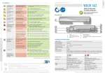
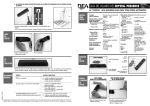
FLY
USER’S GUIDE
PASSIVE INFRARED SENSOR FOR AUTOMATIC DOORS
1
General information
Terminal block
Sensor fixing screw
(black)
LED
Dip-switch
Bracket
Lens
Bracket fixing screw (aluminium)
RED LED FLASHING
LED flashes for a few seconds after power-on.
RED LED LIGHTS UP
Sensor detects motion.
Installation
1
Opening and closing the sensor
FLY
3
LED-signal
To open the Fly sensor, insert a screwdriver in the hole under the
bracket cam.
Consider the position of the guide pin when closing the
sensor.
To open the FSA insert a screwdriver as shown (left) or pinch off
both sides of the front cover (right).
Insert the bottom of the front cover to the bottom clip of
the base and push to close the FSA.
FSA
2
1/4
2
Mounting the sensor
1.
2.
3.
4.
FLY
5.
6.
7.
1.
2.
3.
4.
FSA - FLYCATCHER
WIRE
OPENING
FOOTPRINTS
5.
6.
1.
2.
Stick the template to the wall.
Drill the 2 holes to fix the FSA and the hole for the
cable.
Open the FSA and cut out a wire opening footprint.
Fix the sensor to the FSA base with the 2
aluminum screws supplied with the Fly.
Connect the sensor using the cable.
Fix the sensor with the 2 black screws and close
the FSA.
Stick the template to the ceiling and cut out the
hole.
Clip the sensor on the FCA and fix it with the 2
washers and the 2 aluminum screws.
Connect the sensor using the cable.
Insert the complete assembly into the ceiling and
fix it using the 2 long, black screws.
FCA-FLYUP
3.
4.
Stick the template to the internal profile.
Drill the 2 holes.
Fix the brackets to both sides of the sensor with
the 2 aluminum screws.
Fix the sensor, with the connector facing you, to
the profile with the 2 black screws.
Make the cut-out in the door profile.
Connect the sensor using the cable.
(See p. 1 for wiring)
Adjust the tilt angle using the brackets.
3
Dip switch settings
ON
DIP SWITCH #1
DIP SWITCH #2
DIP SWITCH #3
ON
Sensitivity high
Passive output (NC)
Hold time: 2 s
OFF
Sensitivity low
(mounting height < 2.2m)
Active output (NO)
Hold time: 0.5 s
1 2 3
2/4
4
Sensing field settings
profile
SIDE VIEW
TOP VIEW
The drawings show the maximum sensing field dimensions. If you install the FLY without accessories (FCA or FSA), you can move the
sensing field position by tilting the sensor to select the required vertical tilt angle. Otherwise, this adjustment is not possible.
2
1
To adjust the sensing field, use the masking
lens. To tailor the sensing field, cut the
segments.
Sensing field examples:
4
Use the guide pins to insert the masking
lens on the front cover.
Position the screwdriver as shown to
remove the masking lens.
Installation tips
The sensor must be firmly fastened
in order to avoid vibrations!
When mounting the Fly, make
sure you apply the brackets
before tightening the screws.
When clipping the sensor on the
FCA, make sure you apply the
washers before tightening the
screws.
Always use the aluminium
screws to fasten the
accessories and the black
screws to fix the sensor!
Using the wrong screws could
damage the sensor!
3/4
5
Troubleshooting
SYMPTOMS
The door will not open and the LED does not
light up.
The door will not open and the LED lights up.
PROBABLE CAUSES
The sensor power is off.
The wiring of the relay output is not connected
correctly.
The mode of the relay output is not correct.
The door opens when no detection occurs
and closes during detection.
The sensing field does not correspond to your The cut of the masking lens is wrong.
requirements.
The detection is very bad.
The sensor might be installed upside down.
6
Cut out a new lens to meet the required sensing
field size.
Check if the sensor is installed with its
connector facing you.
: passive infrared and microprocessor
: P.I.R. with 4 elements, 15 lenses with full independent masking possibilities
: 3 m max
: 2.5 m (W) x 1.5 m (D)
: 0.5 m (W) x 0.5 m (D)
: motion
: 0.1 to 1.5 m/s
: 1 red LED
: 10 s
: 0.5 s or 2 s
: < 200 ms
: 12 VDC -10% to 24 VDC+30% / 12 to 24 V AC +/-10 %
: 50/60 Hz
:<1W
: terminal block
: < 0.5 mm²
: 2.5 m
: from –30°C to + 55°C
: 60 V DC/ 42 V AC
: 1A (resistive)
: 30W (DC) / 60 VA(AC)
: Electromagnetic Compatibility (EMC) according to 2004/108/EEC
: anthracite grey or white
: anthracite grey, white or aluminum coloured
: 101 mm (W) x 41 mm (H) x 27 mm (D)
: 91 mm (W) x 40 mm (H) x 40 mm (D)
: 121 mm (W) x 51 mm (H) x 40 mm (D)
Product range & accessories
+
FLY
=
FCA: Fly Ceiling Accessory
FLYUP: Kit for mounting in ceiling
=
+
FLY
42.0235 / V2 – 04.08
Change the position of dip-switch 2.
Technical specifications
Technology
Optical characteristics
Mounting height
Maximum Detection area (mounting height: 2.2m)
Minimum Detection area (mounting height: 2.2 m)
Detection mode
Detection speed
Light indicator
Warm up time
Hold time
Response time
Power supply
Frequency
Power consumption
Connection
Recommended cable section (terminal block)
Length of cable
Temperature range
Standard output relay (free potential contact)
Max. contact voltage
Max. contact current
Max. switching power
Conformity
Colors
Fly
FCA and FSA
Dimensions
Fly
FCA
FSA
7
CORRECTIVE ACTION
Check the wiring and the power supply.
Check the supplied voltage.
Check the relay wiring.
FSA: Fly Surface Accessory
FLYCATCHER: Kit for mounting on wall
Main cable 2.5m
BEA SA - LIEGE Science Park - Allée des Noisetiers 5 - B-4031 Angleur - Tel: +3243616565 - Fax: +3243612858 - [email protected] - www.bea.be
4/4