1
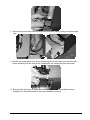
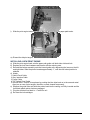
www.isys-group.com iTerra Lite User Guide iSys - The Imaging Systems Group Inc. © Copyright 2009 Rev 002 Table of Contents Ordering Replacement Supplies Unpacking Interface Setup & Configuration Driver Installation for Windows XP Driver Installation for Windows Vista Connectivity Interface Change (Parallel to Network) Connectivity Interface Change (Network to Parallel) Printing Preferences Loading Consumables Print media Installing fan fold paper Install ink cartridges Installation of the Desktop Input and Output media Trays Desktop input tray installation Desktop output tray installation Installation of the Rack Input and Output Media Trays Rack mount input tray installation Rack mount output tray installation Installation of optional rack input bottom tray (for rack install only) Operation Menu guide settings Changing menu settings Menu options Maintenance Replacing ink cartridges Print engine expectant life cycle Removal of old print engine Installing a new print engine Troubleshooting Service & Support Specifications Functional Electrical Physical Operating environment Safety Information Warranty 4 5 5 6 15 23 24 26 27 27 27 27 28 28 29 30 30 31 32 33 33 33 33 35 35 35 36 38 39 42 42 42 43 43 43 43 46 2 iSys is an ISO 9001 Registered Firm Thank you for selecting the iTerra Lite. iSys will make every effort to assist you with operation of your new printer. It is our sincere desire that your ownership experience meets your highest expectations. This user guide is provided to help you easily install and operate your new printer. It contains important information on the features and functions of the iTerra Lite. Please read this manual before using the printer, in particular the Installation and Operation Chapters, and the “Regular Maintenance” section in the Maintenance Chapter. Pay special attention to warnings, cautions and notes. WARNING: A WARNING indicates the potential for personal injury. CAUTION: A CAUTION provides additional information which, if ignored, may result in equipment malfunction, damage or personal injury. NOTE: A NOTE indicates special attention is required. This Symbol indicates an area of possible concern due to static discharge into the circuitry. When you see this symbol in the manual, please observe proper precautions to minimize damage to circuitry. ILLUSTRATIONS: Illustrations and components are representative only. Your unit may differ slightly from those pictured in this document. Need Help? If you require additional assistance or information, please contact the iSys Technical Support team at: iSys - The Imaging Systems Group Inc. 911 28th Street N.E. Calgary, AB T2A 7X1 Canada Toll Free in North America: 1-800-415-4797 Phone: (403) 204-5212 Fax: (403) 204-1971 E-mail: [email protected] THE INFORMATION CONTAINED IN THIS DOCUMENT IS SUBJECT TO CHANGE WITHOUT NOTICE. EXCEPT AS PROVIDED BY LOCAL LAW, THE IMAGING SYSTEMS GROUP INC. (ISYS) MAKES NO WARRANTY OF ANY KIND WITH REGARD TO THIS MATERIAL, INCLUDING, BUT NOT LIMITED TO THE IMPLIED WARRANTIES OF MERCHANTABILITY AND FITNESS FOR A PARTICULAR PURPOSE. ISYS SHALL NOT BE LIABLE FOR ERRORS CONTAINED HEREIN OR FOR INCIDENTAL OR CONSEQUENTIAL DAMAGES IN CONNECTION WITH THE FURNISHING, PERFORMANCE OR USE OF THIS MATERIAL. Trademarks: Centronics is a trademark of Centronics Data Corp. Veratec is a Trademark of Xerox Corp. 3 Ordering Replacement Supplies To purchase Ink Cartridges or Media Online visit our website at www.isys-media.com Using non-Qualified iTerra Lite media and consumables will void the printers’ warranty. • Reach iSys toll free by phone at 1-866-415-4797 within North America or 1-403-204-5200 globally. • Reach iSys by fax at 1-403-204-1971. • All prices in US dollars. • Credit Cards accepted. • Sales tax, and shipping and handling are added where applicable. • An iSys purchase can be used to order products directly if the order value is over $500, excluding freight and taxes and if you have been approved for credit. Paper Media 1000 Sheet Standard Coated Fanfold – 8 Per Case iSys Part Number iJ-SCFF1000 Ink Cartridges Description Black – 1 Cartridge Color (CMY) – 1 Cartridge Black – 20 Per Case Color (CMY) – 20 Per Case iSys Part Number iJ-BK56 iJ-CMY57 IJ-BK56-20 IJ-CMY57-20 Kits Description 20 Black Ink Cartridges 20 Color (CMY) Ink Cartridges 16 Boxes of 1000 Sheet Standard Coated Fanfold iSys Part Number IJ8-KIT 4 Unpacking Shipments are thoroughly checked for completeness. Please confirm receipt of the following: iTerra Lite Printer AC Power Cord Black Ink Cartridge Color Ink Cartridge Driver and User Guide CD Sample Paper Centronics™ - IEEE DB25M to CE36M Cable (Standard unless Network or USB Connectivity) Network Card (Optional – Mounted Internally at Factory) USB External Dongle (Optional) Confirm that any specified options are present, such as a data cable. Inspect the printer and components for any damage that may have occurred during shipment. Report any damage to the carrier of the shipment, and to your Imaging Systems Group Inc. product representative. Keep the box and packaging for future shipping in the event of servicing or upgrading issues. This product must be returned to our factory in the original or proper packaging material. The Imaging Systems Group Inc will not cover damage caused during return shipping or due to improper packaging. Please ensure all ink cartridges are removed before shipping & the print carriage returned to right hand cradle assembly. (Refer to section ‘Install Ink Cartridge’, without reinstalling another cartridge). Interface Setup & Configuration Plug the power cord into a grounded AC outlet. Ensure your power source can supply this unit and any other units sharing the same outlet. See specifications for watt usage of this unit. Centronics™ Connect Centronics™ cable to the parallel port on your host computer and to the Centronics™ port on the back of your iTerra Lite. Ensure cables are locked in place to ensure proper connection. NOTE: The iSys Fast Port must be installed to get optimal data transfer to printer or printer may print at slower speeds when using Centronics™. To install FAST PORT Insert Disc provided by iSys Select the Set up File under the Fast Port Folder Follow these steps: 1. Install Shield Wizard – Press Next 2. Input user name and organization – Press Next 3. Destination Folder. Change the folder name or Press Next to Install 4. Install Wizard Completed – Press Finish 5. A “readme.txt” file will pop up and give you the instructions to ensure FAST PORT installed. Using iSys Fast Port 1. After running setup.exe, an icon “Fast Port” will appear on the Desktop. 2. To use the Fast Port, double click the icon then set the port speed and restart the computer. Once your computer has restarted, set the BIOS parallel setting to ECP. If your BIOS setting does not have this option, you cannot use fast speed mode for iSys printers in your computer. 3. Fast Port is specially designed for iSys printers. You may need to change the speed mode back to slow mode while using other printers. 4. This program will only affect the speed of the LPT ports. 5 Driver Installation for Windows XP STEP 1 Go to Windows Start h Settings h Printers and Faxes hAdd a printer STEP 2 Welcome to the Add Printer Wizard h Press Next 6 STEP 3 Select Local printer attached to this computer h Press Next STEP 4 Select Create a new port: Type of port h Standard TCP/IP Port h Press Next 7 STEP 5 Welcome to the Add Standard TCP/IP Printer Port Wizard h Press Next STEP 6 Enter the printers IP Address into the box h Press Next 8 STEP 7 Under Device Type h Select Custom h Settings STEP 8 Select Raw hPort Number 4400 h Press OK OR Select LPR hQueue Name d1prn h Press OK (SHOWN IN STEP 9) 9 STEP 9 Select LPR hQueue Name d1prn h Press OK OR Select Raw hPort Number 4400 h Press OK (SHOWN IN STEP 8) STEP 10 Under Device Type h Select Customh Press Next 10 STEP 11 Completing the Add Standard TCP/IP Printer Port Wizard h Press Finish STEP 12 Select Have Disk 11 STEP 15 Locate the iTerra Lite driver file (.inf) h Press OK STEP 16 Select the iSys iTerra Lite Printer h Press Next 12 STEP 17 Add the Printer name STEP 18 Select Yes or No to print a test page h press Next 13 STEP 19 If this message appears after installing the driver h Select Continue Anyway STEP 20 Completing the Add Printer Wizard h press Finish 14 Driver Installation for Windows Vista STEP 1 Select Add a printer STEP 2 Select Add a local printer 15 STEP 3 Create a new port h Select type of port: Standard TCP/IP Port h Press Next STEP 4 16 Select Device type: TCP/IP Device h Enter the IP address h Press Next STEP 5 Select Device Type: Custom h Settings STEP 6 Select Raw hPort Number 4400 h Press OK OR Select LPR hQueue Name d1prn h Press OK (SHOWN IN STEP 7) 17 STEP 7 Select LPR hQueue Name d1prn h Press OK OR Select Raw hPort Number 4400 h Press OK (SHOWN IN STEP 6) STEP 8 Select Custom h Press Next 18 STEP 9 Select Have Disk STEP 10 Locate the iTerra Lite driver file (.inf) h Press OK 19 STEP 11 Press Next STEP 12 Type a name for the printer h Press Next 20 STEP 13 During installation a window will appear asking you to verify the driver publisher h Press Install this driver software anyway STEP 14 Choose a sharing option h Press Next 21 STEP 15 You’ve successfully added the printer h You may print a test page h Press Finish 22 Connectivity Interface Change (Parallel to Network) Remove the two screws holding the Centronics™ bulkhead from the plotter. Pull the Centronics™ bulkhead plate away from the plotter. Detach the Centronics™ interface Ribbon cable by lifting the tabs on the connector. Now you can install the network interface. 23 Plug the network interface ribbon cable into the connector and make sure the lift tabs are in the closed position on the ribbon cable. Slowly insert the network bulkhead into the plotter and replace the screws. Now you are ready to use your network interface. Connectivity Interface Change (Network to Parallel) Remove the two screws from the network bulk face plate. Pull the Network bulkhead plate away from the plotter. 24 Detach the Network interface Ribbon cable by lifting the tabs on the connector. Now you can install the Centronics™ interface. Plug the Centronics™ interface ribbon cable into the connector and make sure the lift tabs are in the closed position on the ribbon cable. Slowly insert the Centronics™ bulkhead into the plotter and replace the screws. Now you are ready to use your Centronics™ interface. 25 Printing Preferences The following contains the default settings. To change these settings, go to Window Start Menu Æ Settings Æ Printers Æ Right mouse click on iTerra Lite Æ Printing Preferences Paper/Quality The Paper/Quality tab allows you to modify the paper options and print quality. Basics The Basics tab allows you to modify paper orientation, page order and view a print preview. 26 Color The Color Tab allows you to modify your color levels; they can be nominally modified on your output. Best results are achieved by using iSys approved media (paper). Loading Consumables PRINT MEDIA Ensure you are using iSys qualified media for all your printing needs. By using qualified media you are ensuring your print quality. For media pricing and availability call iSys Media Inc. at 1-866-415iSys or www.isys-media.com. INSTALLING FAN FOLD PAPER Ensure eye mark is face up on the right hand side. The first piece of paper should not have the ‘I’ mark on it. Place paper slowly into the lower opening (media input area). Gently push paper in approximately 8 inches until it stops. Press offline and then form feed. Paper should then sync itself with the TOF (I marks). Put printer to online status. ***Never pull on paper to remove a print job. Failure to do so will cause printer to error and you will have to re-boot. Mechanical failure can also occur. Use form feed & advance menu items to mechanically move paper when in printer. INSTALL INK CARTRIDGES 1. Ensure power is on and menu display is lit up 2. Place printer offline 3. Open printer by pushing the front black levers toward each other (located on the left and right side of the front of the printer) 4. Slide printer forward 5. For each cartridge – raise cradle latch, insert print cartridge, then close cradle latch 6. Close unit 7. Place printer back online 27 Installation of the Desktop Input and Output media Trays DESKTOP INPUT TRAY INSTALLATION a) b) c) Figure # Install 1 Figure # Install 2 Input Media Tray - Desktop iSys Output Media Tray – Desktop iSys Part# KIT-PPR-IT8LD Part# KIT-PPR-IT8LDR In preparation for installation, assemble all the parts in the intended installation area. This should be on a flat tabletop area with space in front for the trays to sit not interfering with traffic flow. You will need a Phillips and a Standard Slotted screwdriver. Figure # Install 3 Figure # Install 4 Place the base plate from ‘Install1’ figure on the table as in figure ‘Install3’, hanging over the edge of the table with right angle firmly against the table top. Position the printer on top of the plate ensuring that the rear printer feet are in the hole slots cut into the base plate (at rear of plate). Positioning of the printer should be as in figure ‘Install4’. Figure # Install 5 Figure # Install 6 28 d) e) Position the desktop version input media tray as in figure ‘Install5’, by hanging the tray portion on the tabs protruding from the base plate. Paper should be installed prior to attaching the output media tray. Place continuous paper in the input tray, with I-marks face up and on right hand side (as in figure ‘Install6’). Ensuring that the first sheet fed is a non I-mark sheet, slowly insert the sheet into the lower slot at the front of printer until resistance is felt (should be approximately eight inches). Press the ‘form feed’ button on the operator panel. The paper will move forward seeking out the first I-mark and setting the top of form alignment. DESKTOP OUTPUT TRAY INSTALLATION Figure # Install 7 Figure # Install 8 a) Using a Phillips screwdriver remove the two screws on the front plate of the printer and replace with the specialized screws found in the Output Tray Kit. The new screws will require a slotted screwdriver. Install the replacement screws and tighten firmly. Properly installed screws will protrude from printer approximately ¼ “ from the printer front plate. Refer to figures ‘Install2 & Install7’ for clarity. b) Hang the tray portion of the output tray over the new screws installed in step a. Figure # Install 9 Figure # Install 10 When the paper is properly fed into the printer (first sheet being a non I-mark sheet), output collection will be uniform and stacked as expected. The output tray will stack or fold up to 500 API sheets maximum. 29 Installation of the Rack Input and Output Media Trays RACK MOUNT INPUT TRAY INSTALLATION Figure # Install 11 a) Installation of the Rack Mount Input and Output trays assumes that the printer has been installed in a rack unit already as in figure ‘Install11’. Optional Rack Mount hardware for various depth racks are available from iSys. Figure # Install 12 Figure # Install 13 Input Media Tray – Rack Mount Output Media Tray – Rack Mount Part# KIT-PPR-IT8LR Part# KIT-PPR-IT8LDR b) Parts required for installation of the rack mount input media tray are found in figure ‘Install12’. Figure # Install 14 Figure # Install 15 c) Taking the input media tray, insert the tabs located at the top side of the tray, into the two slots located on the front of printer as in figures ‘Install14 & Install15’. 30 Figure # Install 16 - correct Figure # Install 17 - incorrect d) Once the tabs have been inserted into the printer, lower the tray in a downward motion until the tray hangs from the printer as in figure ‘Install16’. An incorrect seating of the tabs in the printer slots may look like that portrayed in figure ‘Install17’. Figure # Install 18 e) Paper should be installed prior to attaching the output media tray. Place continuous paper in input tray, with I-marks face up and on the right hand side (as in figure ‘Install18’). Ensuring that the first sheet fed is a non I-mark sheet, slowly insert the sheet into the lower slot at the front of the printer until resistance is felt (should be approximately eight inches). Press the ‘form feed’ button on the operator panel. The paper will move forward seeking out the first Imark and setting the top of form alignment. RACK MOUNT OUTPUT TRAY INSTALLATION Figure # Install 19 Figure # Install 20 c) Using a Phillips screwdriver remove the two screws on the front plate of the printer and replace with the specialized screws found in the Output Tray Kit. The new screws will require a slotted 31 screwdriver. Install the replacement screws and tighten firmly. Properly installed screws will protrude from printer approximately ¼ “ from the printer front plate. Refer to figures ‘Install19 & Install20’ for clarity. d) Hang the tray portion of the output tray over the new screws installed in step a. Figure # Install 21 Figure # Install 22 Properly installed input and output media are in the ‘Install21 and Install22’ figures. When the paper is properly fed into the printer (first sheet being a non I-mark sheet), output collection will be uniform and stacked as expected. The output tray will stack or fold up to 500 API sheets maximum. INSTALLATION OF OPTIONAL RACK INPUT BOTTOM TRAY (FOR RACK INSTALL ONLY) Figure # Install 23 Rack Input Bottom Tray – (Rack Mount only) iSys Part# KIT-PPR-ITL1000 Installation of the rack input bottom tray is best performed by a technician with experience. The rack input bottom tray ships with no additional rack hardware. Mounting of the rack input bottom tray is intended to be placed in a rack immediately below the iTerra Lite printer. Failure to mount as described may result in improper media feed to the printer. Figures ‘Install24 and Install25’ show the installed rack input bottom tray accompanied with the optional output media tray). Figure # Install 24 Figure # Install 25 32 Paper should be installed in the rack input bottom tray and fed into the printer before installing the output tray. Paper should be installed with the black “I-mark” visible on the right hand side. Please refer to previous instructions on proper paper installation. Operation MENU GUIDE SETTINGS CHANGING MENU SETTINGS 1. To use the Menu you must first press offline. 2. Press Menu (far right button). Press Select 3. To choose a selection – press Select – Press Deselect to save changes 4. To Exit – scroll down to exit, then select. **If you need to re-boot the printer without using the rear power switch, press and hold the middle button for 2 seconds. The printer will go into soft power off mode. Press the middle button again (holding for 2 seconds) and printer will perform reboot sequence. MENU OPTIONS Page 1 Plot Control 1 – TOF (Top Of Form) Seek If “on” media advances to next TOF (I - mark) If “off” printing will commence immediately (no line up with TOF) 2 – TOF Alignment Allows you to adjust from 0 – 0.5 inch forward from top of form. The default is 0.20 inches and goes up and down by 0.02 increments. 3 – EOJ Advance (End of Job) Allows you to advance paper out of printer from 0 to 12.5 inches 4 – Exit Pen Maintenance 1 – Pen Clean Allows you to ensure ink cartridges are free of debris, dust, clogging, etc. Options are “yes” and “no”. 2 – Pen Alignment Must be done after install of new ink cartridges to ensure proper alignment between black and color pens. (Registration). Options are “yes” and “no”. Printer Test Test Page – select Test Page to print. Options are “yes” and “no”. Engine Page – select Engine Page to print. This works best on 8.5x11 cut sheet. Options are “yes” and “no”. 33 Page 2 Adjustments TOF Sensor – allows you to adjust the sensor when troubleshooting. Your printer has been configured at the factory to sense low black density I-marks, so adjustment is not normally required. If you feel you need to make adjustments to the sensor, please contact an iSys certified technician and you will be walked through the process. CAUTION: Careful consideration must be taken when you are to make these changes. Warnings/Errors Ink Cartridge Levels are detected. You may adjust at what level of ink remaining you wish to be warned, have the printer “stop” or no warning requiring operator intervention to detect when ink has run out. Available settings are: 1. Off – No warning or interruption of print job will occur, ink will run out and operator will be the only intervention. May require restarting of jobs due to printing without ink. 2. Warning – Will Flash Warning Signal. No job interruption occurs. Warn Black = 0% Color = 0% Warn Black = 5% Color = 5% Warn Black = 10% Color = 10% 3. Stop – Printer will stop with these settings and will ask “Do you wish to continue?” Change ink cartridge and then Press Yes and printer will continue. Stop Black = 0% Color = 0% Stop Black = 5% Color = 5% Stop Black = 10% Color = 10% Defaults – Restores printing preferences back to factory defaults Default Settings 1. TOF Seek On 2. TOF Align +0.20” 3. End of Job (EOJ) Advance Off 4. Ink Levels Off 5. LCD Contrast 4 6. Sound Option Off 34 Page 3 Control Panel LCD Contrast – Allows you to select from 1 – 8 the contrast of the lighting on your display. Different environmental operating conditions may require this setting to be adjusted. Sound Options – Allows you to set your error sounds by time (30 sec, 5 sec, or Off). When sound audible is active, press any front panel key and beeping will stop. Firmware Upgrade This allows you to upload a firmware file, provided by iSys - The Imaging Systems Group Inc., from your host computer. (Options are Upload File – Yes/No) Instructions and new firmware will be posted on the website: www.isys-group.com. You will normally be notified by iSys - The Imaging Systems Group Inc. if updating is required. Front Panel Soft Power Off and On This printer is equipped with a ‘soft power off’ and on setting that is most useful for printers installed in a rack mount setting. This feature can be accessed when panel display is in the main status mode. ‘Soft power off’ the printer by pressing the middle front panel button for greater than 2 seconds. Printer will go into powered off mode and yellow status light will blink once per second. Power the unit back on by pressing the middle front panel button for greater than 2 seconds. Printer will go through standard boot up sequence. Maintenance REPLACING INK CARTRIDGES 1. Power must be on when loading and unloading ink cartridges. Place printer offline. 2. Open printer by pushing the front black levers toward each other (located on the left and right side of the front of the printer) 3. Slide printer forward 4. For each cartridge – raise cradle latch, insert print cartridge, then close cradle latch 5. Close unit 6. Place printer back online 7. Run Pen Alignment for proper registration PRINT ENGINE EXPECTANT LIFE CYCLE Your printer engine is warranted for 60,000 sheets (8.5” x 11”), or 55,000 feet, or 105,600 well log sheets (6.25” in length) or six months (which ever occurs first). 35 How Do I know when to replace my Print Engine? When print quality starts to noticeably deteriorate and you have performed various maintenance sequences, it is highly likely that your print engine has reached End Of Life Cycle. Contact iSys - The Imaging Systems Group Inc. at 1-866-415-iSys (4797) and ask to speak with a service agent, to confirm print engine needs to be replaced. Upon determination of print engine end of life, you can order the replacement engine from iSys – The Imaging Systems Group Inc., by calling 1-866-415-iSys (4797). Replacement engine part number is iL-ENG. NOTE: Upon receipt of print engine component from iSys or a registered reseller, proceed to removal of old print engine and then on to installation of a new print engine sections within this manual. REMOVAL OF OLD PRINT ENGINE a) Place the printer on a stable, horizontal surface or have another individual assist. Slide the black printer lock switches (located on front of printer) towards the middle of the printer and slowly slide the printer out from the main chassis no more than 3.5 inches. b) Remove the ink cartridges (see Replacing Ink Cartridges) c) Unplug printer from wall socket. d) Open the printer and slide forward until stopped by rear rail guide retainers. e) Unplug the switch panel cable (Located left front behind switch panel) f) Unplug the grey interface cable – Lift up the top and bottom lock down clips (Located back right) g) Unplug the power cable (Located back right) h) Unplug the TOF switch panel cable (Located back right) 36 i) Remove the ground wires from the printer and the bottom plate by pulling on the blue cable clips j) Release the bottom panel of the printer by pressing the left and right levers and pulling the bottom assembly from the internal rails, releasing the two components from each other. k) Remove the 2 red wing nuts on the back left and right and other associated lock down hardware. Put these items aside for the engine installation process. 37 l) Slide the print engine toward the rear of the unit and free from the paper path tracks. m) Discard the old print engine. INSTALLING A NEW PRINT ENGINE a) Slide the print engine back onto the paper path guide until both sides click and lock. b) Replace the lock down hardware and secure with the red wing nuts. c) Reinstall the bottom assembly onto the internal guide rails, depressing the levers on the left and right sides. Slide the printer inwards approximately 1”, until the rear locked position is attained. d) Attach: 1. Switch Panel Cable. 2. Grey Interface Cable. 3. Power Cable. 4. TOF Switch Panel Cable. 5. Ground Wires – secure in two places by pushing the blue clips back on to the secured metal clips (one on rear of print engine, the other on main chassis component). e) Depress the guide locks and slide the printer back into the casing, until fully inserted and the front black plastic printer locks are engaged. f) Plug the electrical cord back in – Power On unit. g) Re-insert the ink cartridges. 38 Troubleshooting Problem: Paper not feeding through printer Description: The paper is not all the way in and the printer is trying to form feed. A flashing orange light will come on and the Status will change to NO PAPER. Solution: Cancel the Job or Load Paper and resume. Ensure the paper is fed into the unit approximately 8 inches or until it stops. Note: Never manually pull on paper to remove a print job. Always go offline first and use form feed or advance options on printer. Failure to do so will result in printer error. Problem: Paper Jam Description: Paper is stuck inside the printer. – LCD Menu – STATUS: ERROR Clear the paper path first by opening the printer and sliding it out from the casing. At the back of the unit (on the inside) you will find a black plastic paper guide. There are 2 black levers on the left and right side – press these inward and guide unit will be free for removal. Remove errant paper from guide area carefully. Put the black paper guide back into place by pressing on both the left and right hand side until you hear it lock into place. Press Restart. Printer will restart. If a print job was in progress it will be automatically cancelled. Ensure there are no paper fragments remaining in the printer. Problem: Printer Does Not Print Description: Job has been sent to printer, but nothing is happening. Power is on. 1. Check connections to printer. 2. Print a test page from the printer ÆGo to Menu ÆPage 1 – Printer Test ÆTest Page – select Test Page to print. Select Yes. If test page prints but job doesn’t, continue to #3. 3. Check for errors in Windows Operating System. 4. Check printing properties – ensure proper printer is selected. Problem: Poor Print Quality Description: Output is hard to read, colors are not strong, streaking or dots appear 1. Print cartridges may be low on ink – Replace ink cartridges 2. Print cartridges may need to be cleaned – See ink cartridge cleaning 3. Paper quality may be poor. Try using iSys qualified coated media. 4. Print engine may have reached end of life – See Print Engine Replacement section Problem: Paper is wrinkling or tearing Description: Physical output of paper is creased or tears 1. Ensure paper width is between 8.5” and 8.75” 2. Paper quality may be poor. Try using iSys qualified coated media. Problem: Can’t make changes to menu settings Description: Keys on printer are locked out Ænothing happens when depressed Solution: 1. Cycle power to printer – shut the unit off for 5 seconds, power back on Problem: Form feed stops before desired length or does not stop at top-of-form (TOF) marks (“I” marks) Description: Advancement of paper is not at preferred position Solutions: 1. Paper quality – If the “I” marks (TOF) are not clearly read by the printer, it may not line up properly. Ensure you are using iSys qualified media. 2. Reset printer to Default Settings, then re-adjust preferred Form Feed options, if desired. Problem: Case Open Description: Error Display: Case Open 39 Solution: Ensure printer is completely pushed back into the case. You should hear the latches on the left and right hand side lock in place. Problem: Pen Not Working Description: Error Display: Pen Incorrect Solution: This means that you have placed the wrong ink cartridge into the ink cartridge slots. Check to make sure that the color ink jet cartridge is on the left and the black ink jet cartridge is on the right. Problem: Pen Failure Description: Error Display: Pen Failure Solution: One of the ink cartridges has become defective and is malfunctioning. Swap out the ink cartridge(s). Problem: Operator panel cable is disconnected Description: Error Display: Swp cable unplugged Solution: This error will occur if the cable connecting the operator panel and the printers main logic has become disconnected. Open printer casing as if you were going to change ink cartridges. Reattach operator display panel, by plugging cable back into fixed panel. If trouble persists, call your service representative. Problems: Grinding Noises when printing Prints stair steps down the left margin of the self-test page The ink carriage slams to the left or right side of the printer Double-printed image or shadowed letters The text is wavy, where it is not straight, going up and down Gaps appear in painted text or images NOTE: Clean the encoder strips only after checking all other issues that cause the symptoms listed above. Run pen alignment and ensure ink cartridges are clean and full. Run the internal test plot Æif successful, problem may be program application or driver related. Cleaning the encoder strips are not to be done except as the last step to prevent the printer from being sent to service. Cleaning encoder strip should not be attempted unless suggested by iSys certified Service personnel. Note: It is important not to clean the encoder strips for the following symptoms: poor media quality, paper jams, paper skewing, ink-cartridge missing dots or white gaps through print, or smeared or streaked black. Solution: Clean the encoder strips (both the horizontal and vertical encoder strips) located inside the printer by following the steps below: CAUTION: Extreme care must be taken during the cleaning process. If too much pressure is placed on the encoder strip, it could become scratched (destroying the etching on the strip), bent, stretched, broken, or dislodged from the inside of the printer. If any of this damage occurs, the printer may become inoperable. 1. Turn off the printer and unplug it from the power source. 2. Open the top-cover and find the horizontal encoder strip. It is a mostly clear strip that reaches from the left to the right and is located above the silver carriage rod. The strip is clear with very fine lines imprinted on it, giving it a light gray appearance. It is approximately 0.5 mm or 0.2 inches high. Figure 1 – Locating the horizontal encoder strip 40 Figure 2 – Locating the horizontal encoder strip 3. If dust is the only foreign matter on the horizontal encoder strip, try blowing the dust off with a blower such as canned air. If needed, go to step 4. 4. Moisten with water a small lint-free cloth or facial tissue. 5. With the water, moisten tissue; gently grasp both the front and the back of the encoder strip. Slide the cloth or tissue back and forth as far as possible, taking care not to touch the carriage rod. 6. After cleaning the encoder strip, close the door, plug in the printer, and turn it on. 7. Print a test page to ensure that the printer is functioning properly. To clean the vertical encoder strip, follow the above steps. The vertical encoder strip is a round, clear disc that can be found on the left hand side of the printer. To rotate the vertical encoder strip to clean throughout, move the middle white disk (without the encoder strip attached) in a clockwise manner. This will cause the encoder strip to move in counter clockwise. ***Note: Ensure the vertical encoder strip is moving counterclockwise. Failure to do so may result in TOF (Top of Form) errors and misalignment. If cleaning the encoder strip does not resolve the problem, please contact iSys - The Imaging Systems Group Inc. at 1-866-415-4797. 41 Service & Support If at any time you wish to contact iSys - The Imaging Systems Group Inc., please do so in any of the following ways: • Via the web: www.isys-group.com • Via e-mail: [email protected] • Via phone: 1-866-415-4797 (toll free North America) or 1-403-204-5212. • Via fax: 1-403-204-1971 Recycle Ink program provided by HP. Access www.HP.com and locate the Product Recycle button, follow links and directions. Specifications FUNCTIONAL Print Speeds: Print Technology: Print Quality: Effective Print Width: Emulation: Print Driver Support: Connectivity: Ethernet Optional: Certification: Paper Handling: Features Media Types: Dimensions: Up to 1 ips (print mode and data dependent) HP Color Inkjet 5 Print modes (3 Continuous) Maximum of 8.5 inches in continuous mode PCL3 + GUI Windows 2000, XP IEEE 1284-Centronics™ (std), USB, 10/100 baseT USB (external), 10/100 baseT Ethernet (Internal), Rack mount tray for 17”, 21”-24” or 30” depth racks, Front mount input trays for Rack and Desktop printer versions, Bottom mount input tray for in rack mounting, Output media trays for Rack and Desktop printer versions. FCC Class A, CE Front loading media guide supports 8.75 inches (width) for continuous printing and 8.5 inches for sheet LCD front operations panel, Auto sensing TOF, Desktop or Rack mount, User replaceable print engine, Autosensing and switching power supply Continuous fanfold, Cut sheet 19”w x 14.25”d x 7”h (uncrated), (48.26 cm x 36.25 cm x 17.8 cm) Weight: Desktop - 32 lbs (15 kg) 43 lbs (20 kg) crated or shipping Rackmount - 42 lbs (19 kg) 53 lbs (24 kg) crated or shipping Black – HP 56 (C6657AN) Tri-Color – HP 57 (C6656AN) Printer Resolution: Continuous- 300 x 300 dpi - Fast Draft, Fast Normal 600 x 600 dpi - Normal Cut Sheet- 300 x 300 dpi – Fast Draft, Fast Normal 600 x 600 dpi – Normal & Best 4800 x 1200 dpi – Maximum dpi (Photo) 42 ELECTRICAL Interface Standard: Optional: Power Consumption: Power Requirements: Input voltage: Input frequency: Centronics™ IEEE-1284 USB (1.1) , 10/100 baseT Ethernet network 63 watts maximum peak 100 to 240 VAC (+/- 10%) 50 to 60 Hz (+/- 3 Hz) PHYSICAL Dimensions: Desktop: Height Width Depth Weight Rack mount: Height Width Depth Weight OPERATING ENVIRONMENT Maximum operating conditions: Temperature: Humidity: Optimal operating conditions: Temperature: Humidity: Storage range Temperature: Humidity: 7.0”, 17.5” 14.25” 32 lbs 7.0” 19” (with Rack Tray) 14.25” 42 lbs 5 to 40 degrees C or 41 to 104 degrees F 15 to 80 percent RH non-condensing 15 to 35 degrees C or 59 to 95 Degrees F 20 to 80 percent RH non-condensing -20 to 60 degrees C, or –4 to 140 degrees F 20 to 80 percent RH non-condensing Safety Information Product and Company Identification Product identification Company undertaking identification Emergency telephone number General information telephone number Hazard Rating Health Flammability Reactivity Special C6657A – No. 57 ink (cyan, magenta and yellow) Hewlett-Packard Company 1000 NE Circle Boulevard Corvallis OR 97330-4239 USA Hewlett-Packard Health Effects Line 1-800-457-4209 (USA and Canada) or Intl +1-503-494-7199 (all other areas) 1-208-323-2551 (in USA and Canada) or Intl +1-208-323-2551 NFPA 1 2 0 none Composition/Information on ingredients - For cyan, magenta and yellow ink formulations Component CAS number % by weight Workplace limits (PEL,TLV) 1,5-pentanediol 111-29-5 <10 not established 2-pyrrolidone 616-45-5 <10 not established 43 2-ethyl-2-(hydroxmethyl)-1,3propanedoil Nitrate compounds Trade secret materials Colorants Water 77-99-6 <10 not established Not specified Not specified Not specified 7732-18-5 <8 <5 <7 balance not established not established not established not established Hazard Identification Primary Routes of Exposure Acute Health Hazards Carcinogenicity First Aid Measures Emergency First Aid Procedures First aid for skin First Aid for eyes First aid of ingestion First aid for inhalation Fire fighting Measures Flashpoint: >141 degrees F, >61 degrees C Extinguishing Media: water, dry chemical, carbon dioxide, foam Additional release Measures Spill or Leak Procedures Skin, eye, oral, and inhalation Skin: May cause slight skin irritation characterized by redness and swelling after prolonged contact. Indications may be masked by color of ink. Eye: May be mildly irritating. Oral: May Cause stomach upset. Contains nitrates which can cause methaemoglobinaemia and respiratory depression. Inhalation: Prolonged inhalation may result in irritation to respiratory tract. No substance in this ink formulation is a listed carcinogen according to ACGIH, EPA, EU, IARC, MAK and OSHA criteria. Call the Hewlett-Packard Health Effects Line at 1-800-4574209 (Intl +1-503-494-7199 outside of USA and Canada) Wash affected areas thoroughly with soap and water. Clothing should be laundered before reuse. Seek medical attention if skin irritation persists. Contact with eyes may cause mild irritation. Immediately flush with large amounts of clean, lukewarm water (low pressure) for at least 15 minutes. Seek medical attention if eye irritation persists. Ingestion of ink may cause stomach upset. Call the HewlettPackard Health effects line (above). Seek medical attention if stomach upset persists. (Contains nitrates, refer to section 3.0 or 11.0) Remove person affected to fresh air area. Not determined Special fire fighting procedures: none -Use absorbent towels to wipe up ink. -Rinse area with damp cloth to remove traces of ink. Handling and Storage KEEP OUT OF REACH OF CHILDREN Shelf Life: 24 months Storage Temperature: -20 to 60 degrees C Special Sensitivity: none Handling and Storage precautions: do not use inkjet cartridge when frozen. Ensure inkjet cartridge exterior is dry before inserting in printer. 44 Physical and Chemical Characteristics Appearance: cyan, magenta and Physical State: liquid at room temperature yellow liquid Boiling Point: not applicable Specific Gravity: 1.06-1.07 g/ml PH: 6.6 to 8.5 Solvent content: <41% Solubility in water: soluble Vapor density: >1 (air = 1.0) Reactivity Stability: stable under normal storage conditions Hazardous polymerization: none Thermal decomposition products: oxides of carbon, nitrogen and water Incompatibilities: strong oxidizers, strong bases, bleach and other hypochlorite containing cleaning agents Disposal Considerations Dispose in accordance with applicable federal, state and local laws. Waste classifications based on aquatic toxicity testing: California – hazardous Washington – non hazardous EU – non hazardous Toxicological Information Refer Hazard Identification and First Aid Measures. The Ink formulation contains nitrates. Nitrates and their derivatives can cause methemoglobinemia and result in respiratory depression. Primary indicators of prolonged overexposure include shortness of breath, headaches, dizziness and cyanosis (bluish skin and lips). Transportation Information Not a regulated article under DOT, IATA, ADT or RID. Regulatory Information According to EU Directive 88/379/EEC, this product is not classified as dangerous and therefore no hazard label is required. For other countries, including the USA, no product label would be required. Contains no chemical required by the State of California for listing under proposition 65. Contains no chemical subject to EPA TSCA 12(b). Disclaimer: This Product Safety Data Sheet is offered without charge to the customers of iSys The Imaging Systems Group, Inc. Data is the most current known to Hewlett-Packard (iSys partner) at the time of preparation and is believed to be accurate. It should not be construed as a guaranteeing specific properties of the products as described or suitability for a particular application. 45 iTerra Lite Warranty iSys - The Imaging Systems Group Inc. (iSys) warrants the iTerra Lite Color Thermal Inkjet Printer (Product) to be free from defects in materials and workmanship and will remedy any such defect according to the terms of this Limited Warranty. iSys warrants the Product to be free from defects in material and workmanship occurring under normal usage, within the normal operating range and duty cycles specified. If the iSys Customer Service Representative Department receives notice of such defects during the warranty period, iSys at its option, and within a reasonable time, will repair or replace the defective Product. A certified iSys service representative shall perform repairs, and such repairs, at the option of iSys, may be performed at the customer site, a dealer site, a service depot or the factory. Replacement Product, at the option of iSys, may be either new or equivalent in performance to new. Delivery is defined by a signed and dated receipt from the original carrier or iSys dealer delivering the Product, or down time for repair and replacement. iSys does not warrant the operation of the Product to be uninterrupted or error free. iSys assumes no liability for and holds itself harmless against any claims of consequential costs or damages which may arise from interruption or error in the operation of the Product. iSys does not warrant defects, malfunctions and/or failures, which in its opinion, result from conditions of improper use, abuse, neglect, operation outside the published environmental specifications, improper site preparation and maintenance, the use of unqualified or unauthorized media (papers, films, toners, inks, fusers or belts), inadequate preventative maintenance, unauthorized modifications or unauthorized maintenance. Such conditions shall render this warranty void and otherwise release iSys from its liability under this Product warranty. Consumables are non-warranty items. All product returned to factory must be accompanied by an RMA number, obtained by calling the iSys Service Department at 403.204.5200. Shipping and handling charges to vendor for repair are the sole responsibility of the customer. iSys will cover shipping charges on the return of the repaired unit for the term of the warranty as stated above. Shipping will consist of Standard Shipment level or Best Effort. Accelerated or Premium Shipping Service is available but costs will be fully born by customer. Any international duties and taxes payable on transporting the repaired unit across international borders will be the responsibility of the customer. The iTerra Lite Color Thermal Inkjet Printer is a Canadian made product and therefore falls under the import/export laws of NAFTA. A written receipt for the Product, showing the date of purchase, dealer’s name, and both the model and serial numbers of the Product must accompany any request or claim for work to be performed under this Limited Warranty. Additional information on obtaining service under this Limited Warranty or for obtaining Extended Warranty coverage contact iSys – The Imaging Systems Group directly at 866.415.iSys (4797) or at 403.204.5200. iSys will repair, or at its option replace, at no charge, any defective component(s) of the Product within six months from the date of purchase. The Print Engine Component is considered a consumable item and is only warranted to 60,000 cut sheets or 55,000 feet. This Limited Warranty extends to the original purchaser only. This Limited Warranty does not extend to consumable items. TO THE EXTENT ALLOWED BY LOCAL LAW, THIS WARRANTY IS EXCLUSIVE AND NO OTHER WARRANTY OR CONDITION, WHETHER WRITTEN OR ORAL, IS EXPRESSED OR IMPLIED AND THE IMAGING SYSTEMS GROUP INC. SPECIFICALLY DISCLAIMS ANY IMPLIED WARRANTIES INCLUDING, BUT NOT LIMITED TO, WARRANTIES OF MERCHANTABILITY, FITNESS FOR A PARTICULAR PURPOSE AND QUALITY SATISFACTION. THE WARRANTY TERMS CONTAINED HEREIN, EXCEPT TO THE EXTENT LAWFULLY PREMITTED, DO NOT EXCLUDE, RESTRICT OR MODIFY AND ARE IN ADDITION TO APPLICABLE STATUTORY RIGHTS. USE OF THE PRODUCT CONSTITUTES ACCEPTANCE OF THIS WARRANTY. Corporate Headquarters: iSys – The Imaging Systems Group Inc. th 911-28 Street NE Calgary AB T2A 7X1 www.isys-group.com 1.866.415.iSys (4797) 46