1
DU® Series 700
User’s Guide
A24014-AA
August 2005
Beckman Coulter, Inc.
4300 N. Harbor Blvd., Fullerton, CA 92834-3100
© Copyright 2005 Beckman Coulter, Inc.
i
DU Series 700 User’s Guide
Copyright, Licenses and Trademarks
Copyright
© Beckman Coulter, Inc., 2005. All rights reserved. No part of this publication may be
reproduced, transcribed, transmitted, or translated into any language in any form by
any means without the written permission of Beckman Coulter, Inc.
Licenses and Trademarks
Beckman Coulter® and DU® are registered trademarks of Beckman Coulter, Inc.
Microsoft and Windows are registered trademarks of Microsoft Corporation in the
United States and other countries.
ii
Table of Contents
Section 1
Introduction
General Information . . . . . . . . . . . . . . . . . . . . . . . . . . . . . . . . . . . . . . . . . . . . . 1
Proper Use . . . . . . . . . . . . . . . . . . . . . . . . . . . . . . . . . . . . . . . . . . . . . . . . . . . . . . . . . . . 1
About this Manual . . . . . . . . . . . . . . . . . . . . . . . . . . . . . . . . . . . . . . . . . . . . . . . . . . . . . . 1
Product Compliance . . . . . . . . . . . . . . . . . . . . . . . . . . . . . . . . . . . . . . . . . . . . . . . . . . . . . 1
Safety Precautions . . . . . . . . . . . . . . . . . . . . . . . . . . . . . . . . . . . . . . . . . . . . . . 2
Electrical Safety . . . . . . . . . . . . . . . . . . . . . . . . . . . . . . . . . . . . . . . . . . . . . . . . . . . . . . . . 2
Safety Against Risk of Fire . . . . . . . . . . . . . . . . . . . . . . . . . . . . . . . . . . . . . . . . . . . . . . . . 2
Chemical and Biological Safety . . . . . . . . . . . . . . . . . . . . . . . . . . . . . . . . . . . . . . . . . . . . 3
Source Lamp Safety . . . . . . . . . . . . . . . . . . . . . . . . . . . . . . . . . . . . . . . . . . . . . . . . . . . . 3
Use of Hazard Information . . . . . . . . . . . . . . . . . . . . . . . . . . . . . . . . . . . . . . . . . . . . . . . . 3
Precautionary Labels . . . . . . . . . . . . . . . . . . . . . . . . . . . . . . . . . . . . . . . . . . . . . . . . . . . . 3
Waste Management and Recycling. . . . . . . . . . . . . . . . . . . . . . . . . . . . . . . . . . . . . . . . . . 4
Section 2
System Description
Systems and Functions . . . . . . . . . . . . . . . . . . . . . . . . . . . . . . . . . . . . . . . . . . 5
Design . . . . . . . . . . . . . . . . . . . . . . . . . . . . . . . . . . . . . . . . . . . . . . . . . . . . . . . 6
Front and Back View . . . . . . . . . . . . . . . . . . . . . . . . . . . . . . . . . . . . . . . . . . . . . . . . . . . . 6
Display . . . . . . . . . . . . . . . . . . . . . . . . . . . . . . . . . . . . . . . . . . . . . . . . . . . . . . . . . . . . . . 6
Tips for Using the Touch Screen . . . . . . . . . . . . . . . . . . . . . . . . . . . . . . . . . . . . . . . . . 7
Ports and Power . . . . . . . . . . . . . . . . . . . . . . . . . . . . . . . . . . . . . . . . . . . . . . . . . . . . . . . 8
Beam Path . . . . . . . . . . . . . . . . . . . . . . . . . . . . . . . . . . . . . . . . . . . . . . . . . . . . . . . . . . . . 9
Source Compartment . . . . . . . . . . . . . . . . . . . . . . . . . . . . . . . . . . . . . . . . . . . . . . . . . . 10
Unpacking the Instrument . . . . . . . . . . . . . . . . . . . . . . . . . . . . . . . . . . . . . . . 10
Operating Environment . . . . . . . . . . . . . . . . . . . . . . . . . . . . . . . . . . . . . . . . . 10
Power Up / Applying Power . . . . . . . . . . . . . . . . . . . . . . . . . . . . . . . . . . . . . . 11
Section 3
Installation
Cell Compartment . . . . . . . . . . . . . . . . . . . . . . . . . . . . . . . . . . . . . . . . . . . . . 13
Cell Holders . . . . . . . . . . . . . . . . . . . . . . . . . . . . . . . . . . . . . . . . . . . . . . . . . . 13
Standard Cell Holder . . . . . . . . . . . . . . . . . . . . . . . . . . . . . . . . . . . . . . . . . . . . . . . . . . . 13
Standard Cell Holder Installation . . . . . . . . . . . . . . . . . . . . . . . . . . . . . . . . . . . . . . . . 14
50 µL Single Cell Holder . . . . . . . . . . . . . . . . . . . . . . . . . . . . . . . . . . . . . . . . . . . . . . . . 15
50 µL Single Cell Holder Installation . . . . . . . . . . . . . . . . . . . . . . . . . . . . . . . . . . . . . 15
Turbidity Cell Holder . . . . . . . . . . . . . . . . . . . . . . . . . . . . . . . . . . . . . . . . . . . . . . . . . . . 16
Turbidity Cell Holder Installation . . . . . . . . . . . . . . . . . . . . . . . . . . . . . . . . . . . . . . . . 16
Multicell Holder . . . . . . . . . . . . . . . . . . . . . . . . . . . . . . . . . . . . . . . . . . . . . . . . . . . . . . . 17
Multicell Holder Installation . . . . . . . . . . . . . . . . . . . . . . . . . . . . . . . . . . . . . . . . . . . . 17
Carousel Holder (Sample Changer) . . . . . . . . . . . . . . . . . . . . . . . . . . . . . . . . . . . . . . . . 18
iii
DU Series 700 User’s Guide
Carousel Holder Installation . . . . . . . . . . . . . . . . . . . . . . . . . . . . . . . . . . . . . . . . . . . . 18
Modules . . . . . . . . . . . . . . . . . . . . . . . . . . . . . . . . . . . . . . . . . . . . . . . . . . . . .19
Sipper Module . . . . . . . . . . . . . . . . . . . . . . . . . . . . . . . . . . . . . . . . . . . . . . . . . . . . . . . . 19
Sipper Module Installation . . . . . . . . . . . . . . . . . . . . . . . . . . . . . . . . . . . . . . . . . . . . . 21
Peltier Temperature Control Module . . . . . . . . . . . . . . . . . . . . . . . . . . . . . . . . . . . . . . . 25
Peltier Temperature Control Module Installation . . . . . . . . . . . . . . . . . . . . . . . . . . . . 25
Switching the Power On . . . . . . . . . . . . . . . . . . . . . . . . . . . . . . . . . . . . . . . . .27
Language Selection . . . . . . . . . . . . . . . . . . . . . . . . . . . . . . . . . . . . . . . . . . . . . . . . . . . . 27
Self-Check . . . . . . . . . . . . . . . . . . . . . . . . . . . . . . . . . . . . . . . . . . . . . . . . . . . . . . . . . . . 27
Main Menu . . . . . . . . . . . . . . . . . . . . . . . . . . . . . . . . . . . . . . . . . . . . . . . . . . .28
Alphanumeric Keypad . . . . . . . . . . . . . . . . . . . . . . . . . . . . . . . . . . . . . . . . . . .30
Instrument Setup Mode . . . . . . . . . . . . . . . . . . . . . . . . . . . . . . . . . . . . . . . . .31
Operator ID . . . . . . . . . . . . . . . . . . . . . . . . . . . . . . . . . . . . . . . . . . . . . . . . . . . . . . . . . . 31
Sample ID . . . . . . . . . . . . . . . . . . . . . . . . . . . . . . . . . . . . . . . . . . . . . . . . . . . . . . . . . . . 32
Date and Time . . . . . . . . . . . . . . . . . . . . . . . . . . . . . . . . . . . . . . . . . . . . . . . . . . . . . . . . 33
Display and Sound Preferences . . . . . . . . . . . . . . . . . . . . . . . . . . . . . . . . . . . . . . . . . . . 34
Lamp Control . . . . . . . . . . . . . . . . . . . . . . . . . . . . . . . . . . . . . . . . . . . . . . . . . . . . . . . . . 34
USB Port . . . . . . . . . . . . . . . . . . . . . . . . . . . . . . . . . . . . . . . . . . . . . . . . . . . . . . . . . . . . 36
Password . . . . . . . . . . . . . . . . . . . . . . . . . . . . . . . . . . . . . . . . . . . . . . . . . . . . . . . . . . . 38
Carousel and Module Options . . . . . . . . . . . . . . . . . . . . . . . . . . . . . . . . . . . . . . . . . . . . 40
Carousel . . . . . . . . . . . . . . . . . . . . . . . . . . . . . . . . . . . . . . . . . . . . . . . . . . . . . . . . . . 40
Sipper Module . . . . . . . . . . . . . . . . . . . . . . . . . . . . . . . . . . . . . . . . . . . . . . . . . . . . . . 41
Peltier Module (Temperature Control) . . . . . . . . . . . . . . . . . . . . . . . . . . . . . . . . . . . . 42
Section 4
User Programs
Storing a User Program . . . . . . . . . . . . . . . . . . . . . . . . . . . . . . . . . . . . . . . . .43
Recalling a User Program . . . . . . . . . . . . . . . . . . . . . . . . . . . . . . . . . . . . . . . .44
Deleting a Stored User Program . . . . . . . . . . . . . . . . . . . . . . . . . . . . . . . . . . .44
Section 5
Fixed Wavelength Mode
Parameter Setup . . . . . . . . . . . . . . . . . . . . . . . . . . . . . . . . . . . . . . . . . . . . . . .45
Section 6
Wavelength Scan Mode
Parameter Setup . . . . . . . . . . . . . . . . . . . . . . . . . . . . . . . . . . . . . . . . . . . . . . .51
Scanning . . . . . . . . . . . . . . . . . . . . . . . . . . . . . . . . . . . . . . . . . . . . . . . . . . . . .55
Section 7
Kinetic/Time Mode
Parameter Setup . . . . . . . . . . . . . . . . . . . . . . . . . . . . . . . . . . . . . . . . . . . . . . .57
Taking the Kinetics Readings . . . . . . . . . . . . . . . . . . . . . . . . . . . . . . . . . . . . .58
Analysis of a Kinetic Run. . . . . . . . . . . . . . . . . . . . . . . . . . . . . . . . . . . . . . . . .59
iv
Section 8
Single Component Analysis Mode (SCA)
Parameter Setup . . . . . . . . . . . . . . . . . . . . . . . . . . . . . . . . . . . . . . . . . . . . . . 61
Standard Curve Setup . . . . . . . . . . . . . . . . . . . . . . . . . . . . . . . . . . . . . . . . . . . . . . . . . . 61
Coefficients Setup . . . . . . . . . . . . . . . . . . . . . . . . . . . . . . . . . . . . . . . . . . . . . . . . . . . . . 64
Reading Standards. . . . . . . . . . . . . . . . . . . . . . . . . . . . . . . . . . . . . . . . . . . . . 65
Analyzing Samples . . . . . . . . . . . . . . . . . . . . . . . . . . . . . . . . . . . . . . . . . . . . . 67
Section 9
Protein Assay Analysis
Method Description . . . . . . . . . . . . . . . . . . . . . . . . . . . . . . . . . . . . . . . . . . . . 69
Bradford . . . . . . . . . . . . . . . . . . . . . . . . . . . . . . . . . . . . . . . . . . . . . . . . . . . . . . . . . . . . 69
Lowry (High) . . . . . . . . . . . . . . . . . . . . . . . . . . . . . . . . . . . . . . . . . . . . . . . . . . . . . . . . . 69
Lowry (Low) . . . . . . . . . . . . . . . . . . . . . . . . . . . . . . . . . . . . . . . . . . . . . . . . . . . . . . . . . 70
Biuret . . . . . . . . . . . . . . . . . . . . . . . . . . . . . . . . . . . . . . . . . . . . . . . . . . . . . . . . . . . . . . . 70
UV280 . . . . . . . . . . . . . . . . . . . . . . . . . . . . . . . . . . . . . . . . . . . . . . . . . . . . . . . . . . . . . . 70
Colloidal Gold . . . . . . . . . . . . . . . . . . . . . . . . . . . . . . . . . . . . . . . . . . . . . . . . . . . . . . . . 70
Bicinchoninate (BCA) . . . . . . . . . . . . . . . . . . . . . . . . . . . . . . . . . . . . . . . . . . . . . . . . . . . 70
Parameter Setup . . . . . . . . . . . . . . . . . . . . . . . . . . . . . . . . . . . . . . . . . . . . . . 71
Standard Curve Setup . . . . . . . . . . . . . . . . . . . . . . . . . . . . . . . . . . . . . . . . . . . . . . . . . . 71
Coefficients Setup . . . . . . . . . . . . . . . . . . . . . . . . . . . . . . . . . . . . . . . . . . . . . . . . . . . . . 74
Reading Standards. . . . . . . . . . . . . . . . . . . . . . . . . . . . . . . . . . . . . . . . . . . . . 75
Analyzing Samples . . . . . . . . . . . . . . . . . . . . . . . . . . . . . . . . . . . . . . . . . . . . . 76
Section 10
Nucleic Acid Analysis
Method Description . . . . . . . . . . . . . . . . . . . . . . . . . . . . . . . . . . . . . . . . . . . . 79
260/280 Ratio . . . . . . . . . . . . . . . . . . . . . . . . . . . . . . . . . . . . . . . . . . . . . . . . . . . . . . . . 79
Single Ratio . . . . . . . . . . . . . . . . . . . . . . . . . . . . . . . . . . . . . . . . . . . . . . . . . . . . . . . . . . 79
Double Ratio & Concentration . . . . . . . . . . . . . . . . . . . . . . . . . . . . . . . . . . . . . . . . . . . . 79
dsDNA, ssDNA, and RNA . . . . . . . . . . . . . . . . . . . . . . . . . . . . . . . . . . . . . . . . . . . . . . . . 79
Oligo DNA Long and Oligo RNA Long . . . . . . . . . . . . . . . . . . . . . . . . . . . . . . . . . . . . . . 80
Oligo DNA Short and Oligo RNA Short . . . . . . . . . . . . . . . . . . . . . . . . . . . . . . . . . . . . . 80
Parameter Setup . . . . . . . . . . . . . . . . . . . . . . . . . . . . . . . . . . . . . . . . . . . . . . 81
260/280 Ratio and Single Ratio . . . . . . . . . . . . . . . . . . . . . . . . . . . . . . . . . . . . . . . . . . . 82
Double Ratio & Concentration . . . . . . . . . . . . . . . . . . . . . . . . . . . . . . . . . . . . . . . . . . . . 83
dsDNA, ssDNA, and RNA . . . . . . . . . . . . . . . . . . . . . . . . . . . . . . . . . . . . . . . . . . . . . . . . 85
Oligo DNA Long and Oligo RNA Long . . . . . . . . . . . . . . . . . . . . . . . . . . . . . . . . . . . . . . 86
Oligo DNA Short and Oligo RNA Short . . . . . . . . . . . . . . . . . . . . . . . . . . . . . . . . . . . . . 87
Analysis of Samples . . . . . . . . . . . . . . . . . . . . . . . . . . . . . . . . . . . . . . . . . . . . 88
Calculations . . . . . . . . . . . . . . . . . . . . . . . . . . . . . . . . . . . . . . . . . . . . . . . . . . 91
Background Correction and Net Absorbance . . . . . . . . . . . . . . . . . . . . . . . . . . . . . . . . . 91
Concentration Calculations . . . . . . . . . . . . . . . . . . . . . . . . . . . . . . . . . . . . . . . . . . . . . . 91
Molecular Weight (Oligo DNA Long/Short) . . . . . . . . . . . . . . . . . . . . . . . . . . . . . . . . . . 92
v
DU Series 700 User’s Guide
Molecular Weight (Oligo RNA Long/Short) . . . . . . . . . . . . . . . . . . . . . . . . . . . . . . . . . . 92
Molar Extinction Coefficient (Oligo DNA Long) . . . . . . . . . . . . . . . . . . . . . . . . . . . . . . . 93
Molar Extinction Coefficient (Oligo DNA Short) . . . . . . . . . . . . . . . . . . . . . . . . . . . . . . . 93
Molar Extinction Coefficient (Oligo RNA Long) . . . . . . . . . . . . . . . . . . . . . . . . . . . . . . . 94
Molar Extinction Coefficient (Oligo RNA Short) . . . . . . . . . . . . . . . . . . . . . . . . . . . . . . . 94
Extinction Coefficient (Oligo DNA/RNA Long/Short) . . . . . . . . . . . . . . . . . . . . . . . . . . . 95
Concentration (Oligo DNA/RNA Long/Short) . . . . . . . . . . . . . . . . . . . . . . . . . . . . . . . . . 95
Melting Temperature (Oligo DNA Long) . . . . . . . . . . . . . . . . . . . . . . . . . . . . . . . . . . . . 96
Melting Temperature (Oligo DNA Short) . . . . . . . . . . . . . . . . . . . . . . . . . . . . . . . . . . . . 96
Section 11
% Dye Incorporation
Method Description. . . . . . . . . . . . . . . . . . . . . . . . . . . . . . . . . . . . . . . . . . . . .99
Parameter Setup . . . . . . . . . . . . . . . . . . . . . . . . . . . . . . . . . . . . . . . . . . . . . .100
Analysis of Samples . . . . . . . . . . . . . . . . . . . . . . . . . . . . . . . . . . . . . . . . . . .101
Section 12
DNA/Protein Tools Mode
Calculations. . . . . . . . . . . . . . . . . . . . . . . . . . . . . . . . . . . . . . . . . . . . . . . . . .103
Protein Concentration from Amino Acid Sequence Data . . . . . . . . . . . . . . . . . . . . . . . 104
Radioactive Decay Correction . . . . . . . . . . . . . . . . . . . . . . . . . . . . . . . . . . . . . . . . . . . 106
Conversions . . . . . . . . . . . . . . . . . . . . . . . . . . . . . . . . . . . . . . . . . . . . . . . . .108
Micrograms or dsDNA to Picomoles . . . . . . . . . . . . . . . . . . . . . . . . . . . . . . . . . . . . . . 108
Example for Conversion Functions . . . . . . . . . . . . . . . . . . . . . . . . . . . . . . . . . . . . . 109
Picomoles of dsDNA to Micrograms and Nanograms . . . . . . . . . . . . . . . . . . . . . . . . . 109
Micrograms/mL of Oligonucleotides (ssDNA) to Picomoles/µL . . . . . . . . . . . . . . . . . 110
Picomoles/µL of Oligonucleotides (ssDNA) to Micrograms/mL . . . . . . . . . . . . . . . . . 110
Micrograms of Linear DNA to Picomoles of Ends . . . . . . . . . . . . . . . . . . . . . . . . . . . . 111
Molar Ratio of Insets to Vector for Ligations . . . . . . . . . . . . . . . . . . . . . . . . . . . . . . . . 111
Nucleic Acid Concentration from Abs@260 . . . . . . . . . . . . . . . . . . . . . . . . . . . . . . . . . 112
Protein Molar Conversion . . . . . . . . . . . . . . . . . . . . . . . . . . . . . . . . . . . . . . . . . . . . . . 113
Protein Coding Capacity . . . . . . . . . . . . . . . . . . . . . . . . . . . . . . . . . . . . . . . . . . . . . . . 114
Temperature Conversion . . . . . . . . . . . . . . . . . . . . . . . . . . . . . . . . . . . . . . . . . . . . . . . 115
Tables . . . . . . . . . . . . . . . . . . . . . . . . . . . . . . . . . . . . . . . . . . . . . . . . . . . . . .115
Nucleotide Naming Conventions . . . . . . . . . . . . . . . . . . . . . . . . . . . . . . . . . . . . . . . . . 115
Standard Genetic Code . . . . . . . . . . . . . . . . . . . . . . . . . . . . . . . . . . . . . . . . . . . . . . . . 116
Amino Acid Codes and Masses . . . . . . . . . . . . . . . . . . . . . . . . . . . . . . . . . . . . . . . . . . 116
DNA/Protein Sizes . . . . . . . . . . . . . . . . . . . . . . . . . . . . . . . . . . . . . . . . . . . . . . . . . . . . 116
DNA Sequence Triplets (Decoder) . . . . . . . . . . . . . . . . . . . . . . . . . . . . . . . . . . . . . . . . 116
Solubility, Density, and pl of Amino Acids . . . . . . . . . . . . . . . . . . . . . . . . . . . . . . . . . . 116
Hydrophobicity of Amino Acids . . . . . . . . . . . . . . . . . . . . . . . . . . . . . . . . . . . . . . . . . . 116
Radioactivity Units . . . . . . . . . . . . . . . . . . . . . . . . . . . . . . . . . . . . . . . . . . . . . . . . . . . . 116
Metric Prefixes . . . . . . . . . . . . . . . . . . . . . . . . . . . . . . . . . . . . . . . . . . . . . . . . . . . . . . 116
vi
Section 13
Carousel, Sipper, and Peltier Operation
Carousel Holder . . . . . . . . . . . . . . . . . . . . . . . . . . . . . . . . . . . . . . . . . . . . . . 117
Fixed Wavelengths Measurements . . . . . . . . . . . . . . . . . . . . . . . . . . . . . . . . . . . . . . . 117
Wavelength Scan . . . . . . . . . . . . . . . . . . . . . . . . . . . . . . . . . . . . . . . . . . . . . . . . . . . . . 118
Kinetics/Time . . . . . . . . . . . . . . . . . . . . . . . . . . . . . . . . . . . . . . . . . . . . . . . . . . . . . . . . 119
Sipper Module . . . . . . . . . . . . . . . . . . . . . . . . . . . . . . . . . . . . . . . . . . . . . . . 120
Fixed Wavelengths Measurements . . . . . . . . . . . . . . . . . . . . . . . . . . . . . . . . . . . . . . . 120
Wavelength Scan . . . . . . . . . . . . . . . . . . . . . . . . . . . . . . . . . . . . . . . . . . . . . . . . . . . . . 121
Kinetics/Time . . . . . . . . . . . . . . . . . . . . . . . . . . . . . . . . . . . . . . . . . . . . . . . . . . . . . . . . 122
Peltier Module . . . . . . . . . . . . . . . . . . . . . . . . . . . . . . . . . . . . . . . . . . . . . . . 123
All Modes . . . . . . . . . . . . . . . . . . . . . . . . . . . . . . . . . . . . . . . . . . . . . . . . . . . . . . . . . . 123
Section 14
Store, Recall, Send, and Delete Data
Storing Data . . . . . . . . . . . . . . . . . . . . . . . . . . . . . . . . . . . . . . . . . . . . . . . . . 125
Storing Data - Auto/Manual . . . . . . . . . . . . . . . . . . . . . . . . . . . . . . . . . . . . . . . . . . . . . 125
Single Reading Mode . . . . . . . . . . . . . . . . . . . . . . . . . . . . . . . . . . . . . . . . . . . . . . . . 125
Continuous Reading Mode . . . . . . . . . . . . . . . . . . . . . . . . . . . . . . . . . . . . . . . . . . . 126
Storing Scans (Wavelength Scan) . . . . . . . . . . . . . . . . . . . . . . . . . . . . . . . . . . . . . . . . 126
Storing Kinetic Data (Kinetics/Time) . . . . . . . . . . . . . . . . . . . . . . . . . . . . . . . . . . . . . . 127
Recalling Data, Scans, and Kinetic Runs . . . . . . . . . . . . . . . . . . . . . . . . . . . 127
Recalling Data . . . . . . . . . . . . . . . . . . . . . . . . . . . . . . . . . . . . . . . . . . . . . . . . . . . . . . . 127
Recalling Scans (Wavelength Scan) . . . . . . . . . . . . . . . . . . . . . . . . . . . . . . . . . . . . . . 128
Recalling Kinetic Data (Kinetics/Time) . . . . . . . . . . . . . . . . . . . . . . . . . . . . . . . . . . . . . 130
Sending Data, Scans, and Kinetic Runs . . . . . . . . . . . . . . . . . . . . . . . . . . . . 131
Sending Data . . . . . . . . . . . . . . . . . . . . . . . . . . . . . . . . . . . . . . . . . . . . . . . . . . . . . . . . 131
Sending Scan Data (Wavelength Scan) . . . . . . . . . . . . . . . . . . . . . . . . . . . . . . . . . . . . 132
Sending Kinetic Data (Kinetics/Time) . . . . . . . . . . . . . . . . . . . . . . . . . . . . . . . . . . . . . 133
Deleting Data, Scans, and Kinetic Runs . . . . . . . . . . . . . . . . . . . . . . . . . . . . 133
Deleting Data . . . . . . . . . . . . . . . . . . . . . . . . . . . . . . . . . . . . . . . . . . . . . . . . . . . . . . . . 133
Deleting Scan Data (Wavelength Scan) . . . . . . . . . . . . . . . . . . . . . . . . . . . . . . . . . . . . 135
Deleting Kinetic Data (Kinetics/Time) . . . . . . . . . . . . . . . . . . . . . . . . . . . . . . . . . . . . . 135
Section 15
Maintenance
Cleaning Requirements . . . . . . . . . . . . . . . . . . . . . . . . . . . . . . . . . . . . . . . . 137
Spectrophotometer . . . . . . . . . . . . . . . . . . . . . . . . . . . . . . . . . . . . . . . . . . . . . . . . . . . 137
Display . . . . . . . . . . . . . . . . . . . . . . . . . . . . . . . . . . . . . . . . . . . . . . . . . . . . . . . . . . . 137
Cell Cleaning Instructions . . . . . . . . . . . . . . . . . . . . . . . . . . . . . . . . . . . . . . . . . . . . . . 137
Cell Description . . . . . . . . . . . . . . . . . . . . . . . . . . . . . . . . . . . . . . . . . . . . . . . . . . . . 137
Cell Cleaning Instructions . . . . . . . . . . . . . . . . . . . . . . . . . . . . . . . . . . . . . . . . . . . . 138
Cell Deterioration . . . . . . . . . . . . . . . . . . . . . . . . . . . . . . . . . . . . . . . . . . . . . . . . . . . 139
Flowcell Maintenance/Cleaning Instructions . . . . . . . . . . . . . . . . . . . . . . . . . . . . . . . . 139
Flowcell Cleaning Instructions . . . . . . . . . . . . . . . . . . . . . . . . . . . . . . . . . . . . . . . . . 139
vii
DU Series 700 User’s Guide
Conditioning a new Flowcell . . . . . . . . . . . . . . . . . . . . . . . . . . . . . . . . . . . . . . . . . . 140
Cleaning Procedure - Daily . . . . . . . . . . . . . . . . . . . . . . . . . . . . . . . . . . . . . . . . . . . 140
Cleaning Procedure - Contaminated Flowcells . . . . . . . . . . . . . . . . . . . . . . . . . . . . . 140
Cleaning Procedure - Severely Contaminated Flowcells . . . . . . . . . . . . . . . . . . . . . . 141
Other information . . . . . . . . . . . . . . . . . . . . . . . . . . . . . . . . . . . . . . . . . . . . . . . . . . 141
Changing Lamps . . . . . . . . . . . . . . . . . . . . . . . . . . . . . . . . . . . . . . . . . . . . . .142
Changing the Tungsten Lamp . . . . . . . . . . . . . . . . . . . . . . . . . . . . . . . . . . . . . . . . . . . 142
Changing the deuterium lamp (UV) . . . . . . . . . . . . . . . . . . . . . . . . . . . . . . . . . . . . . . . 143
Changing the Fuse. . . . . . . . . . . . . . . . . . . . . . . . . . . . . . . . . . . . . . . . . . . . .144
Changing the Filter Pad . . . . . . . . . . . . . . . . . . . . . . . . . . . . . . . . . . . . . . . . .145
Section 16
Troubleshooting
Power Up Diagnostics . . . . . . . . . . . . . . . . . . . . . . . . . . . . . . . . . . . . . . . . . .147
Error Messages . . . . . . . . . . . . . . . . . . . . . . . . . . . . . . . . . . . . . . . . . . . . . . .148
Other Error Conditions . . . . . . . . . . . . . . . . . . . . . . . . . . . . . . . . . . . . . . . . .149
Section 17
System Check
Call System Check from the Main Menu . . . . . . . . . . . . . . . . . . . . . . . . . . . .151
Instrument Information . . . . . . . . . . . . . . . . . . . . . . . . . . . . . . . . . . . . . . . . .151
Upgrading the Instrument Software . . . . . . . . . . . . . . . . . . . . . . . . . . . . . . .152
Optical Checks. . . . . . . . . . . . . . . . . . . . . . . . . . . . . . . . . . . . . . . . . . . . . . . .152
Wavelength Check . . . . . . . . . . . . . . . . . . . . . . . . . . . . . . . . . . . . . . . . . . . . . . . . . . . . 153
Noise Check . . . . . . . . . . . . . . . . . . . . . . . . . . . . . . . . . . . . . . . . . . . . . . . . . . . . . . . . . 154
Stray Light Check . . . . . . . . . . . . . . . . . . . . . . . . . . . . . . . . . . . . . . . . . . . . . . . . . . . . 154
Absorbance Check . . . . . . . . . . . . . . . . . . . . . . . . . . . . . . . . . . . . . . . . . . . . . . . . . . . . 155
Drift Check . . . . . . . . . . . . . . . . . . . . . . . . . . . . . . . . . . . . . . . . . . . . . . . . . . . . . . . . . . 156
Lamp History. . . . . . . . . . . . . . . . . . . . . . . . . . . . . . . . . . . . . . . . . . . . . . . . .157
Factory Service . . . . . . . . . . . . . . . . . . . . . . . . . . . . . . . . . . . . . . . . . . . . . . .157
Section 18
Specifications
Performance Specifications. . . . . . . . . . . . . . . . . . . . . . . . . . . . . . . . . . . . . .159
Physical and Environmental Specifications . . . . . . . . . . . . . . . . . . . . . . . . . .159
Power and Other Specifications . . . . . . . . . . . . . . . . . . . . . . . . . . . . . . . . . .160
Section 19
Replacement Parts, Service Centers, and Warranty
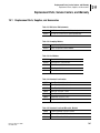
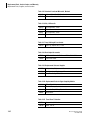
Replacement Parts, Supplies, and Accessories . . . . . . . . . . . . . . . . . . . . . . .161
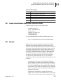
Repair Service/Beckman Coulter Sales and Service Offices. . . . . . . . . . . . . .163
Warranty . . . . . . . . . . . . . . . . . . . . . . . . . . . . . . . . . . . . . . . . . . . . . . . . . . . .163
viii
Introduction
General Information
1
1.1
1
Introduction
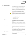
General Information
The spectrophotometer has been designed in accordance with the
current state of the technology and the acknowledged safety
regulations.
The manufacturer certifies that this instrument was thoroughly
tested, inspected, and found to meet its published specifications
when it was shipped from the factory.
Nevertheless, under certain circumstances users may be at risk, or
the proper functioning of the instrument may be impaired.
WARNING If risk-free operation is not possible, the instrument should not
be switched on or it should be properly switched off and secured against
being switched on unintentionally.
This is the case when:
r
The instrument is visibly damaged.
r
An electrical failure occurs.
r
The temperature is above 70°C.
r
Transport damage occurs.
Proper Use
The spectrophotometer is solely intended for carrying out
individual measurements or series of measurements for laboratory
analysis.
Beckman Coulter, Inc. cannot accept liability for any harm caused
to persons or property as a consequence of using the instrument for
any purpose other than those defined in the manual.
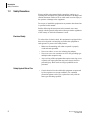
About this Manual
This manual contains all the information needed to enable the
instrument to be operated without any problems throughout its life
span.
The manual is intended for use by the personnel who operate the
instrument. Accident- and trouble-free operation of the instrument
can only be assured by adhering strictly to the instructions in the
manual. Such adherence results in less down-time and lower repair
costs, and increases the lifesaving of the instrument.
Product Compliance
This equipment complies with Class A limits for the FCC and
EN 55011 requirements.
DU Series 700 User’s Guide
PN A24014-AA
1
Introduction
Safety Precautions
1.2
Safety Precautions
Please read this entire manual before unpacking, setting up, or
operating this instrument. Pay particular attention to all danger and
caution statements. Failure to do so could result in serious injury to
the operator or damage to the equipment.
Do not use or install this equipment in any manner other than what
is specified in this manual.
Besides following the instructions in this manual, users must
comply with the general safety and accident prevention regulations
of the country in which the instrument is used.
Electrical Safety
To reduce risks of electric shock, this equipment is equipped with a
three-wire electrical cord and plug to connect the equipment to
earth ground. To preserve this safety feature:
r
Make sure the matching wall outlet receptacle is properly
wired and earth grounded.
r
Never use a three- or two-wire isolating plug adapter.
r
Never use a two-wire extension cord or a non-grounding type
multiple outlet receptacle strip.
r
Any servicing of this equipment that requires removing covers
or panels can expose parts that may cause electric shock or
personal injury. Refer such servicing to qualified service
personnel.
r
Certain electrical circuits within this equipment are protected
by fuses against over-current conditions. For continued
protection against a risk of fire, replace fuses only with the
same type and rating specified.
Safety Against Risk of Fire
2
DU Series 700 User’s Guide
PN A24014-AA
Introduction
Safety Precautions
1
Chemical and Biological Safety
Normal operation of this instrument may involve using toxic,
flammable, or biologically harmful chemicals. Users must take
these precautions:
r
Observe all cautionary information printed on the original
solution containers prior to using them.
r
Handle infectious samples in accordance with good laboratory
procedures and methods to prevent spread of disease.
r
Dispose of all waste solutions in a proper manner.
r
When using hydrochloric acid to clean the flow cell, observe
standard laboratory safety procedures. Wear protective eye
covering and immediately wash any splashes from skin or
clothing with plenty of water.
r
Since concentrated Trace-Klean is a highly alkaline solution,
handle it with care.
Source Lamp Safety
The source lamps operate at high temperatures.
r
To avoid a possible electric shock, disconnect the instrument
from the power source before servicing the lamps.
r
To prevent a possible burn, allow the lamp(s) to cool at least
30 minutes before handling.
r
The UV lamp generates UV light. Do not look directly at an
operating lamp without wearing UV protective eye glasses.
Use of Hazard Information
The following symbols appear in the manual:
WARNING Users must comply with this warning for their own safety.
Failure to do so may result in an injury.
WARNING This symbol, if noted on the instrument, indicates a hot surface.
NOTE A note contains important information which users must take into
account when handling the instrument.
Precautionary Labels
Read all labels and tags attached to the instrument.
Personal injury or damage to the instrument could occur if not
observed.
This symbol, if noted on the instrument, refers to the instruction
manual for operational and/or safety information.
DU Series 700 User’s Guide
PN A24014-AA
3
Introduction
Safety Precautions
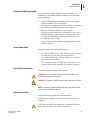
Waste Management and Recycling
This symbol is required in accordance with the Waste Electrical
and Electronic Equipment (WEEE) Directive of the European
Union. The presence of this marking on the product indicates that
the device:
A016608L.EPS
1.
was put on the European Market after August 13, 2005 and
2.
must not be discarded using the municipal waste collection
system of any member state of the European Union.
Customers must understand and follow all laws regarding the
proper decontamination and safe disposal of electrical equipment.
Please contact your dealer or local Beckman Coulter office for
details on the take-back program that will facilitate the proper
collection, treatment, recovery, recycling, and safe disposal of
Beckman Coulter products bearing this label.
4
DU Series 700 User’s Guide
PN A24014-AA
System Description
Systems and Functions
2
2.1
2
System Description
Systems and Functions
The DU Series 700 Spectrophotometer is a complete scanning
UV/Visible spectrophotometer with a bandwidth of 3 nm and a
wavelength range of 190 to 1100 nm. The instrument comes with a
complete set of application programs and multi-language support.
The DU Series 700 includes two models:
r
DU 720 General Purpose
r
DU 730 Life Science
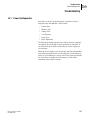
The DU 720 contain the following modes:
r
Fixed Wavelength
r
Wavelength Scanning
r
Time-based Kinetic
r
Single Component Analysis
The DU 730 contains the following modes:
r
Fixed Wavelength
r
Wavelength Scanning
r
Time-based Kinetic
r
Single Component Analysis
r
Protein Assay Analysis
r
Nucleic Acid Analysis
r
% Dye Incorporation
r
DNA/Protein Tools
The system comes with a Standard Single Cell Holder for a 1-cm
rectangular cuvette. A test tube holder is fixed in the sample
compartment. Other sampling devices, such as a 7-Cell Carousel, a
Sipper Module, and a Peltier Temperature Control Module are
optional.
You can use the DU Series 700 for testing samples in the visible
and ultraviolet wavelength spectrum. A halogen gas-filled tungsten
lamp produces light in the visible spectrum (320 to 1100 nm), and a
deuterium lamp produces light in the ultraviolet spectrum (190 to
360 nm).
The DU Series 700 Spectrophotometer provides digital readouts in
Absorbance or %Transmittance as well as calculated units,
depending on the mode. USB ports for printer, keyboard, and
memory devices are standard.
DU Series 700 User’s Guide
PN A24014-AA
5
System Description
Design
When you select a user-generated or programmed method, the
on-screen menus and prompts direct you through the test. You can
also use these menus to generate reports, run statistical evaluations
of generated calibration curves, and report instrument diagnostic
checks.
2.2
Design
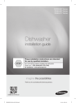
Front and Back View
Figure 2.1 Front and Back View
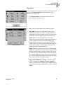
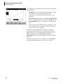
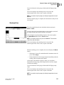
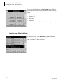
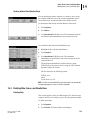
Display
Display
The display is a touch-screen device and the content changes as you
select different modes of operation. Figure 2.2 shows the two main
menu screens with the available application programs of the DU
730.
6
DU Series 700 User’s Guide
PN A24014-AA
System Description
Design
2
Figure 2.2 Main Menu Screens
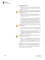
Tips for Using the Touch Screen
The entire screen is touch-activated (touch screen). Spend a few
minutes touching various items on the screen to see how they
work.
r
Take time to touch the individual fields lightly to get familiar
with their functions.
r
To make a selection, touch the screen with your fingernail,
fingertip, pencil eraser, or a stylus.
NOTE Only the supplied stylus ensures efficient use of the touch screen!
WARNING Do not touch the screen with a sharp object, such as the tip of
a ball point pen!
WARNING Do not place anything on top of the cover; doing so could
scratch it!
DU Series 700 User’s Guide
PN A24014-AA
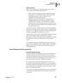
r
Touch keys, words, or icons to select them.
r
Use scroll bars to move up and down long lists very quickly.
Touch and hold the scroll bar, then move your fingertip up or
down to move through the list.
r
Highlight an item from a list by touching it once. After you
select the item, the screen displays the selected item in
reversed text (light text on a dark background).
7
System Description
Design
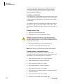
Ports and Power
The power connector and power switch are locate on the back wall
of the instrument.
The DU Series 700 Spectrophotometer has three USB ports as a
standard feature. They are located on the back wall of the
instrument. These USB ports enable you to output data and
graphics to a printer or memory device.
Figure 2.3 Ports and Power
3
4
5
2
1
901606.ai
8
1
Downstream ("B") USB connector
2
Two upstream ("A") USB connectors for Printer, Keyboard, and/or
Memory Device.
3
On/Off switch
4
Fuse
5
Plug-in Power Supply
DU Series 700 User’s Guide
PN A24014-AA
System Description
Design
2
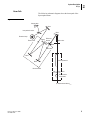
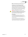
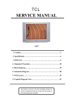
Beam Path
The following schematic diagram shows the beam path of the
Spectrophotometer.
Figure 2.4 Beam Path
Halogen lamp
Mirror
Lamp selection mirror
Mirror
Deuterium lamp
Entrance slit
ReferenceGrating element
Splitter mirror
Filter
Exit slit
Mirror
Mirror
Cell compartment
Monochromator
Lens
Round cuvette
compartment
Measurement element
901604.ai
DU Series 700 User’s Guide
PN A24014-AA
9
System Description
Unpacking the Instrument
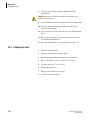
Source Compartment
The source compartment is on the left side behind the display inside
of the instrument. It is provided with ventilation on the back side.
The lamp compartment contains the halogen and deuterium (UV)
lamps.
A fan used for cooling the sample compartment and electric
components is mounted on the back side. The ventilation system
operates automatically.
In general, you should maintain a clear space of at least 15 cm (6
inches) around the instrument for safety. Good ventilation prevents
the electronic components from overheating, which helps to extend
the life span of the instrument.
WARNING The cover can become hot, especially when a deuterium lamp is
used! Do not place anything on top of the cover!
For information on replacing halogen and deuterium lamp, see
"Changing Lamps" on page 142.
2.3
Unpacking the Instrument
1. Remove the DU Series 700 Spectrophotometer and accessories
from the shipping container.
2. Inspect each item for any damage that might have occurred
during shipment.
3. Verify that all items listed in Standard Accessories are
included. If any items are missing or damaged, contact your
regional Beckman Coulter office or distributor.
4. Do not send the instrument back without previous arrangement.
5. Place the instrument firmly on an even table surface.
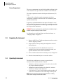
2.4
Operating Environment
The following conditions are necessary to ensure that the
instrument runs smoothly and has a long life.
r
Maintain an ambient temperature of 10 to 40ºC (50 to 104ºF)
for proper instrument operation.
r
Maintain the relative humidity at less than 90%; moisture
should not condense on the instrument.
r
Leave at least a 15 cm (6 inch) clearance at the top and on all
sides for air circulation to avoid overheating electrical parts.
NOTE Protect the instrument from temperature extremes, including
heaters, direct sunlight, and other heat sources.
10
DU Series 700 User’s Guide
PN A24014-AA
System Description
Power Up / Applying Power
2.5
2
Power Up / Applying Power
r
Plug the supplied power cord into the connector on the back of
the instrument and a main socket
(100 – 120 V~ / 200 - 240 V~ / 50 – 60 Hz).
NOTE The unit is shipped with a UL/CSA approved 115 Vac power cord
with a NEMA 5-15P style plug (North America) or a 230 Vac harmonized
power code with a continental European plug.
DU Series 700 User’s Guide
PN A24014-AA
r
Use only earthed sockets.
r
Check the power cable for damage before use.
11
System Description
Power Up / Applying Power
12
DU Series 700 User’s Guide
PN A24014-AA
Installation
Cell Compartment
3
3.1
3
Installation
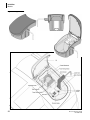
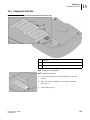
Cell Compartment
The spectrophotometer has been designed in accordance with the
current state of the technology and offers a choice of different
modules and interchangeable cell holders for specific applications.
To prevent external light from interfering with the measurement,
the cell compartment has a light-proof cover.
NOTE Close the cover before taking a measurement!
Figure 3.1 Cell Compartment
901601.ai
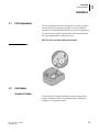
3.2
Cell Holders
Standard Cell Holder
The DU Series 700 Spectrophotometer comes equipped with a
Single Cell Holder, which is the Standard Holder. It holds one
standard 1 cm rectangular cuvette.
DU Series 700 User’s Guide
PN A24014-AA
13
Installation
Cell Holders
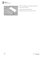
Figure 3.2 Standard Cell Holder
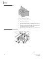
Standard Cell Holder Installation
To assemble the Standard Cell Holder:
1. Open the cell compartment.
2. Insert the cell holder into the cell compartment (see Figure 3.3.)
3. Take care to position the holder exactly. The metal pins of the
cell compartment should lock into the holder.
4. Secure the front part of the holder with the two locking screws.
Figure 3.3 Installing the Standard Cell Holder
14
DU Series 700 User’s Guide
PN A24014-AA
Installation
Cell Holders
3
50 µL Single Cell Holder
The 50 µL Single Cell Holder only accepts 50 µL Microcells from
Beckman Coulter, Inc.
Figure 3.4 50 µL Single Cell Holder
50 µL Single Cell Holder Installation
To assemble the 50 µL Single Cell Holder:
1. Open the cell compartment.
2. Insert the cell holder into the cell compartment in such a way
that the locking screws on the holder are at the front.
3. Take care to position the holder exactly. The metal pins of the
cell compartment should lock into the holder.
4. Secure the front part of the holder with the two locking screws.
Figure 3.5 Installing the 50 µL Single Cell Holder
DU Series 700 User’s Guide
PN A24014-AA
15
Installation
Cell Holders
Turbidity Cell Holder
The Turbidity Cell Holder is designed to give accurate quantitative
measurements of light scatter in the DU Series 700
Spectrophotometer with conventional forward-optics design.
Use this cell holder when you want to quantitate bacterial cultures
or other turbid samples by absorbance measurements.
Figure 3.6 Turbidity Cell Holder
Turbidity Cell Holder Installation
To assemble the Turbidity Cell Holder:
1. Open the cell compartment.
2. Insert the cell holder into the cell compartment in such a way
that the locking screws on the holder are at the front.
3. Take care to position the holder exactly. The metal pins of the
cell compartment should lock into the holder.
4. Secure the front part of the holder with the two locking screws.
Figure 3.7 Installing the Turbidity Cell Holder
16
DU Series 700 User’s Guide
PN A24014-AA
Installation
Cell Holders
3
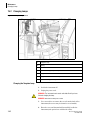
Multicell Holder
The Multicell Holder can accommodate the following cuvette
types:
•
10, 20, and 50 mm rectangular cuvettes
•
1-inch round cuvettes
•
1-inch rectangular cuvettes
You can use only one cuvette type for a measurement. On the top
and bottom of the Multicell Holder are a variety of openings that
accommodate different types of cuvettes. Beside each opening is
printed the type of cuvette for which it is intended.
Figure 3.8 Multicell Holder (Top and Bottom)
4
1
2
3
5
1
10 mm rectangular cuvette
2
20 mm rectangular cuvette
3
50 mm rectangular cuvette
4
1-inch round cuvette
5
1-inch rectangular cuvette
901602.ai
Multicell Holder Installation
To assemble the Multicell Holder:
1. Open the cell compartment.
2. Identify the correct opening for the selected cuvette type in the
Multicell Holder.
3. Insert the Multicell Holder in the cell compartment with the
cell opening at the front so you can read the name of the
selected cuvette type directly.
DU Series 700 User’s Guide
PN A24014-AA
17
Installation
Cell Holders
4. Secure the holder with two locking screws.
Figure 3.9 Installing the Multicell Holder
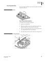
Carousel Holder (Sample Changer)
The Carousel Holder allows you to load up to seven cuvettes of
solution into the instrument for analysis at one time. The cuvettes
can be various combinations of blanks and samples. Use the Setup
Mode to activate the Carousel Options and set up the number of cell
positions used and the orientation of blanks and samples.
Figure 3.10 Carousel Holder
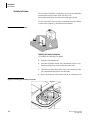
Carousel Holder Installation
To insert the Carousel Holder:
1. Open the cell compartment.
2. Place the Carousel Holder on the rotatable attachment on the
bottom of the cell compartment so that the marking faces
upward.
18
DU Series 700 User’s Guide
PN A24014-AA
Installation
Modules
3
3. Take care to position the holder exactly. The markings on the
holder and the rotatable attachment must line up exactly.
4. Turn the holder slightly to the left or right until the guide key
locks into position. This establishes contact with the
instrument. (For instrument setup options and procedures, see
"Carousel and Module Options" on page 40).
Figure 3.11 Installing the Carousel Holder
3.3
Modules
This section describes how to install the Sipper and Peltier
Temperature Control Modules.
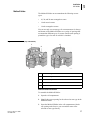
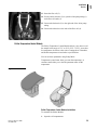
Sipper Module
The Sipper Sampling Module uses a peristaltic pump to aspirate
samples into a flow cell for readings. After the module takes a
reading, it returns the sample or dumps it to waste.
The Sipper Sampling Module provides improved measurement
accuracy, because the same optical characteristics exist for both
blanking and reading, and when comparing measurements of
different samples. The module eliminates errors that might occur
from optical differences between individual vials because it takes
every reading in the same vial.
DU Series 700 User’s Guide
PN A24014-AA
19
Installation
Modules
Figure 3.12 Sipper Module
20
DU Series 700 User’s Guide
PN A24014-AA
Installation
Modules
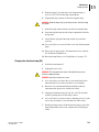
3
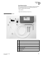
Sipper Module Installation
Remove the Sipper Module from the shipping container and inspect
for any damage that may have occurred during shipment. All
models are shipped with the following:
• Sipper Module
• Sipper Accessories Kit (see Figure 3.13)
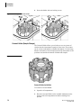
Figure 3.13 Sipper Accessories Kit
DU Series 700 User’s Guide
PN A24014-AA
1
Rubber fitting
2
Flow Cell
3
Outlet Connector (from pump to drain)
4
Sample/Inlet Tubing
5
Drain/Waste Tubing
6
Pump Tubing (white)
7
2 locking screws
8
Guide tube
21
Installation
Modules
Figure 3.14 Sipper Module with Tubes in Place
1
Pump Tubing (white)
2
Outlet Connector (from pump to drain)
3
Flow Cell
4
Sample/Inlet Tubing
5
Drain/Waste Tubing
6
Guide tube
Before you install the Sipper Module in the DU Series 700
Spectrophotometer, you need to connect a number of tubes.
22
DU Series 700 User’s Guide
PN A24014-AA
Installation
Modules
3
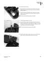
To install the Sipper Module:
1. Draw the drain tube through the exit channel of the sipper
from the inside outwards. The push-on connectors must be
inside the sipper.
2. Draw the inlet tube through the entry channel of the sipper
from the outside inwards. The push-on connectors must be
inside the sipper.
NOTE Take care to avoid causing any kinks in the tubes!
3. Turn the Sipper Module on its side.
4. Draw the inlet tube and the drain tube through, respectively,
the entry channel and the exit channel of the sipper. The inlet
tube must be drawn through the guide tube. The bottom end of
the guide tube must click into the channel.
NOTE Take care to avoid causing any kinks in the tubes!
5. Hold the rubber fitting with the ridges over the grooves and
push it firmly onto the guide tube and the waste tube.
DU Series 700 User’s Guide
PN A24014-AA
23
Installation
Modules
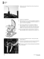
6. Make sure the rubber fitting firmly encloses the guide tube
and the drain tube.
7. Open the cell compartment.
8. Without the locking screws, insert the Standard Cell Holder or
Microcell Holder (see "Standard Cell Holder Installation" on
page 14) in the cell compartment.
9. Place the Sipper Module on the Standard Cell Holder or
Microcell Holder in such a way that the screw holes are
positioned exactly one above the other. The lid of the Sipper
Module can be opened towards the back of the instrument.
10. Secure the Sipper Module and the Standard Cell Holder or
Microcell Holder with two locking screws (see Figure 3.13).
11. Pull the pump adjustment forward (1) and open the pump
tubing clamp (2).
12. Wrap the white pump tubing around the pump and clamp the
ends on the right and left in the front two retainers (3).
NOTE The push-on connectors of the pump tubing must be positioned as
shown in the illustration.
24
DU Series 700 User’s Guide
PN A24014-AA
Installation
Modules
3
13. Insert the flow cell (3).
14. Use the outlet connector (2) to join the white pump tubing (1)
to the flow cell outlet (3).
15. Connect the drain tube (5) to the right end of the white pump
tubing.
16. Connect the inlet tube to the inlet of the flow cell (4).
Peltier Temperature Control Module
The Peltier Temperature Control Module allows you to heat or cool
the sample in the range of 15°C to 50°C (59°F - 122°F), set an alert
for temperature deviation, select units of centigrade or Fahrenheit,
and disable temperature control after a specified time.
You can set these parameters using Setup Mode.
Temperature control starts when you enter the temperature; it
continues until either you or the idle parameter turns off the
temperature.
Figure 3.15 Peltier Module
Peltier Temperature Control Module Installation
To assemble the Peltier Module:
1. Open the cell compartment.
DU Series 700 User’s Guide
PN A24014-AA
25
Installation
Modules
2. Insert the Peltier Module in the cell compartment with the
module lid open toward the back of the instrument (see Figure
3.16).
3. Secure the Peltier Module with two locking screws.
Figure 3.16 Installing the Peltier Temperature Control Module
26
DU Series 700 User’s Guide
PN A24014-AA
Installation
Switching the Power On
3.4
3
Switching the Power On
To switch on the instrument:
1. Close the cell compartment.
2. Press the power switch on the back.
WARNING Do not switch the instrument off and on in rapid succession.
Always wait about 5 seconds before switching the instrument on again;
otherwise, you may damage the electronic and mechanical systems.
Language Selection
The software of the DU Series 700 Spectrophotometer includes
several language options. To choose a language:
1. While turning on the instrument, touch the display until the
screen displays the list of languages.
2. Select the desired language.
3. Touch OK to confirm the language selection. The self-check
starts automatically.
NOTE The instrument continues to power up using the selected
language, until you select a different language.
Self-Check
Each time you power up the instrument, it performs a series of
diagnostic tests automatically to ensure operation of major system
components.
This procedure, which takes approximately two minutes, checks
the system, lamps, wavelength calibration, filter adjustment, and
voltage. The display adds a check mark next to the test name to
confirm its functionality.
When power-up diagnostics are complete, the Main Menu
appears.
NOTE If any function does not pass or if any error messages appear
during self check, see "Troubleshooting" on page 147.
DU Series 700 User’s Guide
PN A24014-AA
27
Installation
Main Menu
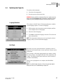
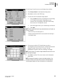
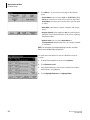
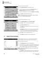
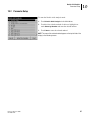
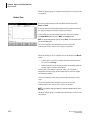
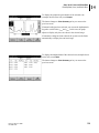
3.5
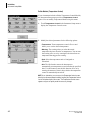
Main Menu
The Main Menu consists of two pages on the DU 730. From there
you can access common functions as well as all the available
applications modes. Table 3.1 identifies each Main Menu soft key
and briefly describes the corresponding operation mode.
r
To display the second page of the Main Menu, touch More....
r
To return to the first page, touch Return.
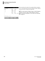
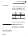
Table 3.1 Main Menu Soft Key Options
Soft Key
Operation Mode
User Programs
The User Program mode lets you recall saved programs.
Fixed Wavelength
The Fixed Wavelength mode collects data at up to 4 wavelengths. You can display
the data in absorbance, transmittance, or concentration. The concentration is
calculated by a user-defined factor or formula.
Wavelength Scan
The Scan Wavelength mode shows how a sample absorbs light over a range of
wavelengths. You can use this feature to optimize instrument sensitivity with a given
chemistry. The screen plots the scan.
Kinetics/Time
The Kinetics/Time Measurement mode records absorbance or % transmittance at a
single wavelength over a specified time period.
Single Component Analysis (SCA)
The SCA mode lets you prepare a standard curve for analyzing samples that
contain one component.
Protein Assay Analysis
The Protein Assay mode provides a simple procedure to calculate the amount of
protein in a sample. It contains pre-selected parameters for seven common protein
assay methods.
28
DU Series 700 User’s Guide
PN A24014-AA
Installation
Main Menu
3
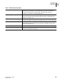
Table 3.1 Main Menu Soft Key Options
Nucleic Acid Analysis
The Nucleic Acid mode provides ten methods for DNA, RNA, and oligonuceotide
analyses, which calculates nucleic acid absorbance ratios and concentrations.
Other calculations include molecular weight, nucleotide length, extinction
coefficient, concentration, and melting temperature.
% Dye Incorporation
The % Dye Incorporation mode works for single- and duo-color methods (spotted
array). This works for any dye that gives similar fluorescence wavelength to Cy3
(550nm) or Cy5 (650 nm).
DNA/Protein Tools
The DNA/Protein Tools mode does not take measurements. The mode provides a
number of calculations, conversations, and tables to aid you in common daily tasks.
System Checks
The System Checks mode lets you check the performance of the instrument
(photometric accuracy, photometric noise, stray light, wavelength accuracy, lamp
history, and printer check).
Recall Data
The Recall Data mode lets you store, recall, send, and erase data from the Datalog.
Instrument Setup
The Instrument Setup mode allows you to configure the instrument and the module,
based on your specific requirements.
DU Series 700 User’s Guide
PN A24014-AA
29
Installation
Alphanumeric Keypad
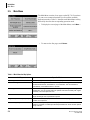
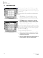
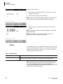
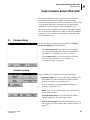
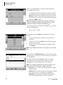
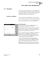
3.6
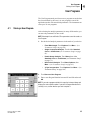
Alphanumeric Keypad
Each time an operation requires input, the alphanumeric keypad
opens. Use this screen to enter letters, numbers, and symbols as
needed when programming the instrument. Unavailable options
are grayed out, indicating that those functions do not apply to your
operation mode.
The icons to the left of the screen allow you to choose an entry
mode:
•
ABC (alphabetic): When entering alphabetic characters
(such as user-entered units), this key allows you to toggle
between upper and lower case letters. It is inactive on some
screens.
•
#% (symbols): Lets you enter punctuation, symbols, and
numerical subscripts and superscripts after touching this key.
•
123 (numeric): Use this key to switch to a numeric keypad
when you need to enter regular numbers.
The central part of the keypad changes to reflect the chosen entry
mode. To enter a character, you must repeatedly touch a key until
the desired character appears on the screen. To enter a space, use
the underscore on the YZ_ key.
The keys to the right side of the screen are:
30
•
CE (clear entry): Clears all text displayed in the entry field.
•
Left Arrow (backspace): Moves the cursor back one position,
deleting the previous character.
•
Right Arrow (advance): Advances the character to display the
next one when the key shows more than one character.
DU Series 700 User’s Guide
PN A24014-AA
Installation
Instrument Setup Mode
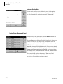
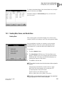
3.7
3
Instrument Setup Mode
To change to Instrument Setup Mode, select Instrument Setup in
the Main Menu.
The Instrument Setup menu displays a list of options you can use
to set instrument functions.
If the instrument recognizes a Sipper module or a Peltier module,
the Carousel Options key is replaced by Sipper Options or
Peltier Options.
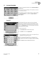
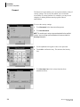
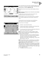
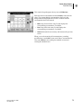
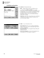
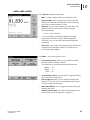
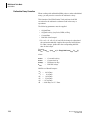
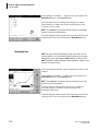
Operator ID
Use the Operator ID screen to enter up to 30 sets of operator
initials (up to five characters each) into the instrument. You can
assign the Operator ID to a measurement from the measurement
screen or the Operator ID menu. This feature helps record which
operator measured each sample.
To create an Operator ID:
1. Touch Operator ID in Instrument Setup mode.
2. Touch New to enter a new Operator ID.
3. Use the alphanumeric keypad to enter a new Operator ID (see
"Alphanumeric Keypad" on page 30).
NOTE Use the alphanumeric keypad to enter a new Operator ID. You
cannot use spaces in this function. Use underscore symbols instead (YZ_
key).
NOTE Touch Delete to remove an Operator ID from the list.
DU Series 700 User’s Guide
PN A24014-AA
31
Installation
Instrument Setup Mode
4. Touch OK to save your changes. The screen returns to the
Instrument Setup menu and shows the selected operator
identifier.
NOTE If an Operator ID is active, you can also touch the Operator ID icon
directly on the Measurement screen. The Operator ID screen opens, in
which you can change the ID.
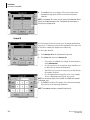
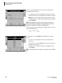
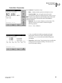
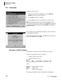
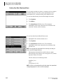
Sample ID
Use the Sample ID screen to enter up to 30 sample identification
tags (up to 13 characters each) into the instrument. You may want
to use this to identify the samples more effectively.
To access this function:
1. Touch Sample ID in the Instrument Setup menu.
2. Touch New and enter a new Sample ID.
r
If you want to subdivide the Sample ID with numbers,
touch Add Number.
r
Use the arrow keys to specify how many numbers can
be added for the sample identification.
r
Touch the key between the arrow keys to add directly
the number of choice.
Use the alphanumeric keypad to enter a new Sample
ID (see "Alphanumeric Keypad" on page 30).
r
NOTE You cannot use spaces in this function. Use underscore symbols
instead (YZ_ key).
3. Touch OK to confirm. The display shows the chosen Sample
ID, as shown in the following illustration.
NOTE Touch Delete to remove a Sample ID from the list.
32
DU Series 700 User’s Guide
PN A24014-AA
Installation
Instrument Setup Mode
3
4. Touch OK to save your changes. The screen returns to the
Instrument Setup menu and shows the selected sample
identifier.
NOTE If a Sample ID is active, you can also touch the Sample ID icon
directly on the Measurement screen to change it. The Sample ID screen
opens, in which you to change the Sample ID.
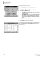
Date and Time
Use the Data & Time screen to set the instrument’s data and time.
1. Touch Date & Time in the Instrument Setup menu. The screen
provides the fields necessary to set the date and time.
2. Touch the appropriate field and use the arrow keys to change
the value.
3. Touch OK to confirm. The screen returns to the Instrument
Setup menu.
DU Series 700 User’s Guide
PN A24014-AA
33
Installation
Instrument Setup Mode
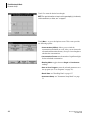
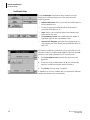
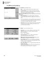
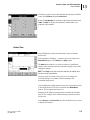
Display and Sound Preferences
Use the Display & Sound screen to set the audiovisual
preferences.
1. Touch Display & Sound in the Instrument Setup menu. The
screen displays four options:
r
Display/Contrast: lets you adjust the display contrast
to suit lighting conditions and viewing angle.
r
Screen touch: The instrument default is off. To make
a short beep every time by touching the screen activate
the Screen touch option.
r
Reading done: The instrument default is set to make a
short beep every time a reading is complete. To turn
off the Reading done sound, deactivate the Reading
done option.
r
Timer: lets you change the length of the timer sound
touch Short or Long. Long beeps are better for noisy
environments.
2. Touch OK to confirm. The screen returns to the Instrument
Setup menu.
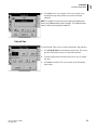
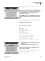
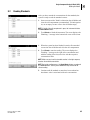
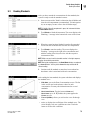
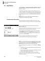
Lamp Control
The halogen gas-filled tungsten lamp produces light in the
visible spectrum 320 to 1100 nm.
The deuterium lamp (UV-lamp) produces light in the ultraviolet
spectrum 190 to 360 nm.
In the overlap zone from 320 to 360 nm, you can use either the
deuterium lamp (UV-lamp) or the halogen lamp for measurements.
The lifetime of the lamps is influenced by on-off operation and the
length of time in use.
Typically, you might turn the instrument on for the entire 8-10 hour
shift, and then off until the next day.
NOTE In general, avoid on/off cycles of the lamp; this shortens the lamp’s
life span. For maximum life, turn the lamp off only if it will remain off for at
least 4-5 hours.
If the instrument needs a lamp for the selected program, or the
instrument is operating inside the lamp’s spectrum, the lamp
switches on automatically.
34
DU Series 700 User’s Guide
PN A24014-AA
Installation
Instrument Setup Mode
3
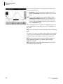
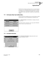
Use the Lamp Control screen to set the lamp timer switches.
1. Touch Lamp Control in the Instrument Setup menu.
2. Select On to switch on the VIS-Lamp.
3. To select the time for automatic lamp shutoff:
a.
Select the Save check box, located below the VIS-Lamp
or UV-Lamp control option. Depending on your
selection, the screen displays either the Visible Lamp
Save screen or UV Lamp Save screen.
b.
Select the length of time you want the lamp switched on.
c.
Touch OK.
NOTE After this period of time the lamp automatically turns off under one
of these conditions:
r
when no activity has taken place or
r
when the measurements have been outside from the lamp’s
wavelength range.
4. If necessary, touch the UV Switch button to select a
wavelength between 320 and 360 nm, at which the instrument
changes from the visible to the UV source. Use the
alphanumeric keypad to enter the switching wavelength.
NOTE Usually, there is no need to change the default value of 331 nm for
the switching wavelength.
5. Touch OK to confirm. The screen returns to the Instrument
Setup menu.
NOTE A program that requires a lamp has the highest priority. If, for
example, the lamp in the Lamp Control screen was turned off but the
current program requires the lamp, the lamp turns on automatically.
DU Series 700 User’s Guide
PN A24014-AA
35
Installation
Instrument Setup Mode
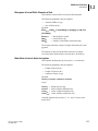
Measuring Mode Effects:
1. UV-Lamp switches on manually. The UV Lamp icon appears
flashing in the display.
2. The instrument displays “Lamp Warmup...”
NOTE For the most accurate and stable measurements in the UV range, let
the lamp warm up for five minutes before taking the first reading.
3. When the lamp is warmed up and ready, the UV icon stops
flashing.
NOTE If both lamps are On, the symbol UV-VIS appears in the selected
Measurement Mode.
NOTE As an alternative, you can touch the UV-Lamp icon on the
measurement screen to change the actual setting.
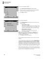
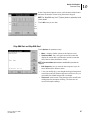
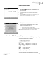
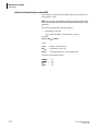
USB Port
As a standard feature, the instrument has three ports, located on the
back wall of the instrument (Figure 2.3). These ports enable you to
output data and graphics to a printer. They also let you connect a
USB keyboard or a memory device.
Table 3.2 Connector Ports
Connector
Description
USB 2 and 3 ("A" Connectors)
These two USB ports let you connect a USB printer, a keyboard, a memory device, or a
device for memory cards. These devices are controlled by the spectrophotometer.
NOTE The printer must have a USB interface and must feature the Printer
Command Language (PCL). Printers that use the Lightweight Imaging
Device Interface Language (LIDIL) or are based on the Printing
Performance Architecture (PPA) require Microsoft Windows and cannot be
used with a DU Series 700 instrument.
36
DU Series 700 User’s Guide
PN A24014-AA
Installation
Instrument Setup Mode
3
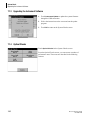
To view a list of devices connected to the ports:
1. Touch USB Port in the Instrument Setup menu. The USB Port
screen displays a list with information about the following
connections:
• Printer
• USB Memory
• Keyboard
NOTE This screen provides information only. The instrument
automatically detects connected devices.
2. Touch OK to return to the Instrument Setup menu.
DU Series 700 User’s Guide
PN A24014-AA
37
Installation
Instrument Setup Mode
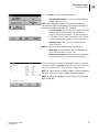
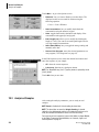
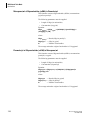
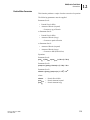
Password
The Password screen enables you to set a password and a variety of
security settings. The security list enables you to control the
accessibility of various functions. For example, you can prevent
changing or deleting different stored programs without
authorization.
To access the security settings:
1. Touch Password in the Instrument Setup menu.
2. Touch Set Password.
NOTE This enables you to assign a password required for the specified
function. You must assign a password before the screen activates the
Security List option.
3. Use the alphanumeric keypad to enter a new password.
4. Touch OK to confirm the entry. This activates the Security
List.
5. Touch Security List to lock various functions from
unauthorized users.
38
DU Series 700 User’s Guide
PN A24014-AA
Installation
Instrument Setup Mode
3
6. Check the functions you want to control by touching each
respective option.
7. Touch OK to confirm the security options selected from the
Security List.
8. Enter the new password again to confirm.
9. Touch OK to return to the Instrument Setup menu.
NOTE Each time a user attempts to perform one of the locked functions,
an alphanumeric keypad opens, in which the user must enter the
password before using those locked functions.
To deactivate a password:
1. Touch Password in the Instrument Setup menu.
2. Use the alphanumeric keypad to enter the former password
and confirm with OK.
3. Touch Set Password. This opens the alphanumeric keypad.
DU Series 700 User’s Guide
PN A24014-AA
39
Installation
Instrument Setup Mode
4. On the alphanumeric keypad, leave the New Password field
blank and touch OK. This deactivates the former password
and returns to the Password screen.
NOTE Use this function to delete the former password or to enter a new
one.
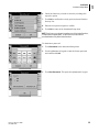
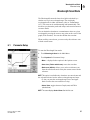
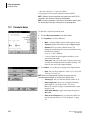
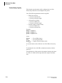
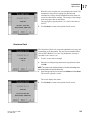
Carousel and Module Options
Carousel
If your instrument includes a Carousel Holder, the Instrument
Setup menu includes Carousel Options. You can activate the
Carousel Holder and modify the carousel parameters using in this
menu.
1. Activate the Carousel Holder:
a.
Touch Carousel Options in the Instrument Setup menu.
b.
Touch Carousel: Off to change its display to
Carousel: On.
c.
Touch OK to confirm your selection.
2. Set the carousel options:
a.
Touch Carousel Options and touch
b.
Select the carousel option of your choice.
For example, the first option is Blank 1 Read 1-7, which
means that the blank cuvette will be read in position 1
while samples must be placed in the cell positions 1-7.
With this option, you must remove the blank cuvette
after blanking.
c.
Use the arrow keys to specify the number of cell
positions you want to use.
3. Touch OK to confirm and return to the Instrument Setup
menu.
NOTE As an alternative, you can access the Carousel Options screen
directly from the measurement mode by touching the Carousel Icon on
the bottom-right of the screen. The Carousel Options screen appears and
you can quickly make the necessary changes.
40
DU Series 700 User’s Guide
PN A24014-AA
Installation
Instrument Setup Mode
3
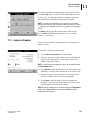
Sipper Module
If your instrument includes a Sipper Module, the Instrument Setup
menu provides Sipper Options. You can modify the sipper
parameters using this menu.
1. Touch Sipper Options in the Instrument Setup menu to
display the Sipper Options screen.
2. Modify the desired parameters for the following options:
• Sip Time: The sip time, in conjunction with the pump
adjustment, determines the amount of sample delivered to
the sample cell. Enter the amount of time (1-99 seconds) for
the pump to run to aspirate the sample into the flow cell.
• Settle Time: The settling time defines how long the
instrument waits between turning off the pump and taking a
sample reading. Use this interval to allow bubbles and
sample turbulence to settle out of the light path. Enter the
amount of time (1-99 seconds) the instrument waits after the
sip time before taking a sample reading. During this time,
the sample stops flowing and stabilizes.
• Purge Time: The purge time, in conjunction with the pump
adjustment, determines the amount of air or rinsing solution
pulled through the sample cell after a reading. This cycle is
optional; you can program the Sipper to recover the sample
or to send the sample to a waste vessel. Enter the amount of
time (1-99 seconds) for the pump to run to empty the sample
from the flow cell after the sample reading.
• Purge Start: Auto/Manual: If Purge is enabled, use this
option to toggle between Manual and Auto. In Manual
mode, you must initiate the sample purge. In Auto mode, the
module automatically purges the sample as soon as a reading
is taken.
DU Series 700 User’s Guide
PN A24014-AA
41
Installation
Instrument Setup Mode
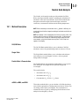
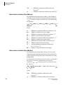
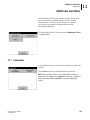
Peltier Module (Temperature Control)
If your instrument includes a Peltier Temperature Control Module,
the Instrument Setup menu provides a Temperature Control
option. You can modify Temperature Modes using this menu.
1. Touch Temperature Control in the Instrument Setup menu to
display the Temperature Control screen.
2. Modify the desired parameters for the following options:
• Temperature: Turns temperature control off or on and
allows you to set the desired temperature.
• Warning: The warning alerts you when the actual
temperature deviates from the set temperature. You can turn
the warning off or to on by entering the deviation from set
temperature that triggers the warning.
• Unit: Select the temperature unit as Centigrade or
Fahrenheit.
• Idle: The idle function causes the instrument to
automatically turn temperature control off after the specified
time. Use this button to turn the idle function off or on by
entering the amount of time in hours before the temperature
control is automatically turned off.
NOTE As an alternative, you can access the Temperature Control screen
directly from the measurement mode by touching the Temperature Control
icon at the bottom-right of the screen. The Temperature Control screen
appears and you can quickly make the necessary changes.
42
DU Series 700 User’s Guide
PN A24014-AA
User Programs
Storing a User Program
4
4
User Programs
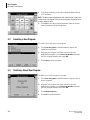
The User Program mode provides access to programs or modes that
have been defined by the user(s). A user program is one of the
application modes with customized parameters. The instrument can
store up to 50 user programs.
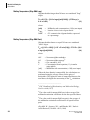
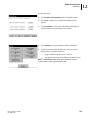
4.1
Storing a User Program
After selecting the analysis parameters in many off the modes, you
can store the parameters for later recall.
NOTE Wavelength Scan and Kinetics/Time parameters cannot be saved as a
User Program.
1. Set the desired analysis parameters in the mode of your choice.
r
Fixed Wavelength: Touch Options then More... (see
"Parameter Setup" on page 45).
r
Single Component Analysis: Touch either Standard
Curve or Coefficients (see "Parameter Setup" on page
61).
r
Protein Assay Analysis: Touch Start, then either
Standard Curve or Coefficients (see"Parameter Setup"
on page 71).
r
Nucleic Acid Analysis: Touch Start, Options, then
More... (see "Parameter Setup" on page 81).
r
% Dye Incorporation: Touch Options then More... (see
"Parameter Setup" on page 100).
2. Touch Save as User Program.
3. Enter a user Program Number between 950 and 999 and touch
OK.
NOTE If you enter a program outside this range, the instrument beeps and
displays the next available number. If you enter a Program Number that is
currently in use, confirm whether you want to replace it.
DU Series 700 User’s Guide
PN A24014-AA
43
User Programs
Recalling a User Program
4. In the Program Name screen, enter a Program Name with up
to 28 characters.
NOTE The alphanumeric keypad appears with a default name (name of the
mode) for the user program. You can use the keypad to change the name
or enter a different name.
5. Touch OK to save the program parameters under the chosen
name and return to the operating mode.
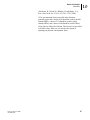
4.2
Recalling a User Program
To recall a previously stored user program:
1. Touch User Programs in the Main Menu to display all
available user programs.
2. Select the user program: touch the respective line and
highlight the program or touch Select by Number and enter
the User Program Number, then touch OK.
3. Touch Start to run the program.
4.3
Deleting a Stored User Program
To delete a previously stored user program:
1. Touch User Programs in the Main Menu to display a list of
all user programs.
2. Select the user program: touch the respective line and
highlight the program or touch Select by Number and enter
the User Program Number, then touch OK.
3. Touch Delete Program.
4. Touch OK to confirm deletion.
44
DU Series 700 User’s Guide
PN A24014-AA
Fixed Wavelength Mode
Parameter Setup
5
5
Fixed Wavelength Mode
The Fixed Wavelength mode lets you collect data at up to 4
wavelengths. You can take and display the data in absorbance or
transmittance and calculate the concentration of your samples using
a factor or a formula.
r
Absorbance measures the amount of light absorbed by the
sample, in units of Absorbance.
r
% Transmittance measures the percent of the original light
that passes through the sample and reaches the detector.
5.1
Parameter Setup
To enter the Fixed Wavelength mode, touch Fixed Wavelength in
the Main Menu.
Touch Options for Parameter Setup. This screen provides the
following options:
• More...: displays more options in the Options screen.
• Store Off/On: lets you toggle the storage setting from Off to
On and manually store data.
• % Trans/Abs: toggles between %Trans (Transmittance) and
Abs (Absorbance) display/readings.
NOTE Abs is in place of %Trans after you have switched to
% Transmittance.
• Timer icon: sets the timer. Using the timer does not affect
the readings that the instrument is taking. The times are not
stored with sample readings.
• λ: lets you enter the wavelength settings.
NOTE The following sections describe how to set the wavelength(s), the
formula, and the coefficients or factors.
DU Series 700 User’s Guide
PN A24014-AA
45
Fixed Wavelength Mode
Parameter Setup
Touch λ to enter the desired wavelength.
NOTE For more information on how to set the wavelength(s), the formula,
and the coefficients, or factor, see "" on page 47.
Touch More… to go to the Options screen. This screen provides
the following options:
• Concentration (Off/On): allows you to switch the
concentration calculation on or off. Also, you can choose the
a formula and determine factor(s) for up to 4 wavelengths to
calculate the concentrations.
• Concentration Format: sets the number of significant digits
for the calculated concentration.
• Reading Mode: toggles between Single and Continuous
readings.
• Save as User Program: stores the selected parameters as a
user program (see "User Programs" on page 43).
• Recall Data: see "Recalling Data" on page 127.
• Instrument Setup: see "Instrument Setup Mode" on page
31.
46
DU Series 700 User’s Guide
PN A24014-AA
Fixed Wavelength Mode
Parameter Setup
5
The Concentration screen lets you switch the concentration
calculation on or off.
When turned On, the Concentration Formula button becomes
enabled and you can touch it to access the Concentration Formula
screen, which allows you to select a formula. The factor(s) for the
concentration calculation are also determined in this screen,
together with the λ selection.
Touch the Unit button to select a concentration unit or add a new
unit to the pre-defined units. You may delete only user-defined
units.
NOTE The selected unit is not shown unless a concentration is calculated
(in this case, the factor must be other than 1.0000 and/or a formula other
than K1 A1 has been selected).
Touch OK to save the parameter setup.
The following formulas are available:
K1 A 1
K1 A 1 + K 2 A 2
K1 A 1 + K 2 A 2 + K 3 A 3
K1 A 1 + K 2 A 2 + K 3 A 3 + K 4 A 4
K1 A 1 / K 2 A 2
(K1 A1 + K2 A2 ) / K3 A3
(K1 A1 + K2 A2 ) / (K3 A3 + K4 A4 )
A1 refers to the absorbance at wavelength 1,
A2 refers to the absorbance at wavelength 2, etc.
K1 refers to the coefficient at wavelength 1,
K2 refers to the coefficient at wavelength 2, etc.
Coefficients can be set negative where subtraction is required.
r
To change the formula, touch the button that displays the
current formula.
r
To change a wavelength, touch one of the "λx:" keys.
r
To change a coefficient, touch one of the "KX:" keys.
Enter the desired wavelength(s) and/or coefficient(s) with the
numeric keypad and touch OK.
NOTE The instrument allows you to enter up to 5 significant digits, with a
maximum of 4 significant digits after the decimal point.
Touch OK to save your selections.
DU Series 700 User’s Guide
PN A24014-AA
47
Fixed Wavelength Mode
Parameter Setup
To set the Concentration Format:
1. Touch Concentration Format in the Options menu.
2. Select the number of significant digits for the concentration
results by touching the respective radio button.
3. Touch OK to confirm.
To select the reading mode:
1. Touch Reading Mode in the Options screen and choose one
of these options:
r
Reading Mode: Single
This feature is available for procedure readings to stop
measurement reading fluctuations on the display once
it reaches a stable reading. This is the default setting.
r
Reading Mode: Continuous
This feature is only available by choosing one
measuring wavelength.
NOTE With the continuous reading mode, only the Blank button is
displayed. The Read button is not available since the readings are
continuous and start automatically.
2. Touch OK to confirm your selection.
Analysis of Samples
After entering the analysis parameters, you are ready to read the
samples.
This description assumes that you have selected Single Reading
(default) as the reading mode and that you are using a cell holder
that holds one cell (the Standard Cell Holder that comes with the
instrument). For instructions on using this function with a Carousel
Cell Holder, the Sipper Module, or the Peltier Temperature Control
Module, see "Carousel, Sipper, and Peltier Operation" on page 117.
Before taking measurements, you need to blank the instrument on
air (no cuvette in the light path) or by using a cuvette with a "blank"
solution, which is recommended for best results.
48
DU Series 700 User’s Guide
PN A24014-AA
Fixed Wavelength Mode
Parameter Setup
5
NOTE Read is disabled until the blank reading is taken.
1. Insert the blank cuvette into the cell holder and close the cell
compartment.
2. Touch Blank to take the blank reading. When done, the
instrument enables the Read button.
3. Insert a sample cuvette into the cell holder and close the cell
compartment.
NOTE If the lid of the cell compartment is open, the instrument disables
the Blank and Read buttons.
4. Touch Read to take the sample reading.
When trying to read a Blank or a Sample, the appropriate source
must be turned on. The system assures that this is the case. You
may observe the following:
r
The UV lamp automatically turns on after you have entered a
wavelength in the UV spectrum. In this case, you have to
wait for the UV lamp to warm up before you can take
readings.
r
During the warm-up phase of the UV lamp, the screen
displays a "Warming up..." message and flashes the UV lamp
symbol. When the UV lamp is turned on automatically, the
instrument performs the reading as soon as the UV lamp is
ready.
When finished reading the sample, the instrument displays the
result (Absorbance Reading or Calculated Concentration).
NOTE For instructions on using a Carousel Cell Holder, a Sipper, or a
Peltier Temperature Controller, see "Carousel, Sipper, and Peltier
Operation" on page 117.
NOTE For instructions on printing and storing data, see "Store, Recall,
Send, and Delete Data" on page 125.
Carousel Holder
DU Series 700 User’s Guide
PN A24014-AA
49
Fixed Wavelength Mode
Parameter Setup
50
DU Series 700 User’s Guide
PN A24014-AA
Wavelength Scan Mode
Parameter Setup
6
6
Wavelength Scan Mode
The Wavelength Scan mode shows how light is absorbed by a
solution over a given wavelength range. You can display
wavelength scans in either Absorbance (Abs) or Transmittance
(%T). The scans can be scaled manually and automatically. This
mode lets you determine peaks and valleys and zoom into areas to
see more details.
You can obtain the absorbance or transmittance values at a given
wavelength by moving the cursor to any point on the x-axis of the
graph (Track function). You can also tabulate the scan data.
When recalling a stored scan, you can overlay this reference scan
with the current scans.
6.1
Parameter Setup
To enter the Wavelength Scan mode:
1. Touch Wavelength Scan in the Main Menu.
2. Touch Options for Parameter Setup.
• More...: displays further options in the Options screen.
• Store Icon (Folder with Arrow): stores the scan data.
• Reference (Off/On): allows you to select a reference scan
from the stored scans and overlay the current scans with the
reference.
NOTE This option is available only when there are stored scans and
the selected reference has the same wavelength range and steps.
• λ: lets you enter the wavelength range (lower and upper
limit as well as the scan resolution or step).
• Select View: toggles between Graph (scan) and Table
(tabular data).
NOTE The screen displays Select View after the first scan.
DU Series 700 User’s Guide
PN A24014-AA
51
Wavelength Scan Mode
Parameter Setup
3. Touch More...: to go to the previous page of the Options
screen.
• Cursor Mode: lets you select Track or Peak/Valley. With
Track, the cursor moves to the next or previous step. With
Peak/Valley, the cursor moves to the next or previous peak
or valley.
• Send Data: sends data to a printer, computer, and storage
device.
• Integral (On/Off): when toggled to On, the scan integral is
displayed in the bottom-left corner of the screen, replacing
the displayed date.
• Scale & Units: lets you select Absorbance or
%Transmittance and determine the y-axis scaling (manual
or automatic).
NOTE For instructions on storing and printing scan data, see "Store,
Recall, Send, and Delete Data" on page 125.
To recall stored scan data to be used as a Reference Scan for
overlays:
1. From the Wavelength Scan mode, touch Options.
2. Touch Reference: Off.
3. In the Select Reference Scan screen, touch the line with the
desired Scan # to highlight it.
4. Touch Highlight Reference or Highlight Data.
52
DU Series 700 User’s Guide
PN A24014-AA
Wavelength Scan Mode
Parameter Setup
6
The system returns to the scan mode, showing the Reference Scan
as an overlay, if a scan has been taken already. The button in the
Options menu now indicates Reference: On.
The Reference Scan is shown in gray and the Measured Scan in
black.
NOTE This option can display only scans that have the same wavelength
range and resolution.
A black and a gray box in the top-left corner of the screen
identifies the scan for which the cursor is active.
Touch the black or gray box in the top-left corner to switch the
cursor from the measured scan to the reference scan and vice
versa.
The bottom-left corner of the display shows the Difference
between the two scans in absorbance or transmittance.
To set the scan or wavelength:
1. Touch the λ key in the Options menu.
2. Touch the top-left button to change the lower limit and enter
the desired value using the numeric keypad.
3. To set the upper limit, touch the top-right button and enter the
desired value using the numeric keypad.
NOTE Do not enter the same value for lower and upper limit. When
entering a value for the lower limit that is higher than the upper limit or
vice versa, the values are reversed.
4. Select the scan resolution or step by touching the respective
radio button. Selecting a larger step allows the instrument to
scan faster, but decreases the resolution of the scan.
Depending on the selected wavelength range, you may select
steps between 0.1 and 5 nm.
NOTE A total of 910 data locations are available for each scan (1100 nm 190 nm = 910) at a 1 nm step. Intervals that exceed this boundary are
automatically grayed out and cannot be selected.
NOTE Recordings of high resolution scans take longer than recordings of
low resolution scans. For example, 0.1 nm resolution is equal to a speed
of 100 nm/min while 5 nm resolution is equal to a speed of 4500 nm/min.
A common and practical scan interval or resolution is 1 nm, which is equal
to a scan speed of 910 nm/min.
5. Touch OK to return to the scan mode.
DU Series 700 User’s Guide
PN A24014-AA
53
Wavelength Scan Mode
Parameter Setup
To set scale and units for the y-axis:
1. Touch Options, More..., and then Scale & Units.
2. Select Abs or %T by touching the radio button.
3. Select Auto or Manual scaling.
r
With Auto scaling (default), the screen scales the scan
to fit the graph area.
r
With Manual scaling, you can set the lower and upper
limits of the y-axis by touching the respective button
and entering the appropriate value using the numeric
keypad.
4. Touch OK to return to the Options screen.
5. Touch Return to return to the scan mode.
To toggle between the scan display (graph) and the tabulated scan
data, touch Select Table or Select Graph in the Options menu
after taking a scan.
54
DU Series 700 User’s Guide
PN A24014-AA
Wavelength Scan Mode
Scanning
6.2
6
Scanning
Before you can take a wavelength scan, you must first scan the
baseline (performing a blank scan). Changing any of the scanning
parameters requires a new baseline scan. After scanning the
baseline, the instrument is ready to take sample scans.
To enter the Wavelength Scan mode:
1. Touch Wavelength Scan in the Main Menu.
2. Insert the cuvette with a "blank" solution into the cell holder
and close the cell compartment (recommended). To blank
against air, use an empty cuvette or leave the cell holder
empty.
NOTE If the lid of the cell compartment is open, the instrument disables
the Blank/Read buttons.
3. Touch Blank to start the baseline scan. The screen displays
the "Blanking..." message in the bottom-left corner of the
screen.
4. When the system has been blanked, insert a sample cuvette
into the cell holder and close the cell compartment.
5. Touch Read to start the scan. The screen displays the
"Reading..." message in the bottom-left corner of the screen.
NOTE During the scanning process, the Read/Blank buttons are
replaced by a Cancel button. You may touch Cancel to stop and discard
the scan in progress.
When the scan is complete, the instrument does the following:
1. Displays the entire scan over the selected wavelength range.
2. Scales the y-axis depending on the selected scaling mode.
3. Activates the cursor functions in the vertical navigation bar.
DU Series 700 User’s Guide
PN A24014-AA
55
Wavelength Scan Mode
Scanning
Located on the right side of the scan graph, three buttons allow
you to navigate the scan:
r
Peak/Valley: Touch the top button to toggle between the
Track and Peak/Valley (button that includes arrows) cursor
modes.
NOTE You can select the default cursor mode in the Options screen.
r
Left/Right arrow buttons: The two arrow buttons in the
vertical menu move the cursor left and right to the next or
previous data point (Track) or the next or previous peak or
valley (Peak/Valley mode).
The wavelength at the cursor position is highlighted at the x-axis
of the graph and the corresponding Abs or %T is highlighted on
the y-axis.
NOTE You can also move the cursor by directly touching on the displayed
graph.
To zoom in (+) or out (-), touch the Zoom Symbol on the left side
of the screen. Zoom enlarges the area around the cursor position.
Touch the Zoom Symbol again to return to the former scale.
NOTE For instructions on using a Carousel Cell Holder, a Sipper, or a
Peltier Temperature Controller, see "Carousel, Sipper, and Peltier
Operation" on page 117.
NOTE For instructions on printing and data storage, see "Store, Recall,
Send, and Delete Data" on page 125.
56
DU Series 700 User’s Guide
PN A24014-AA
Kinetic/Time Mode
Parameter Setup
7
7
Kinetic/Time Mode
The Kinetic/Time mode lets you collect data in either absorbance or
transmittance for a user-defined length of time. After collecting the
data, you can display the kinetic profile or the tabular data and
calculate the rate or slope of a given time range.
7.1
Parameter Setup
To enter the Kinetics/Time mode:
1. Touch Kinetics/Time mode in the Main Menu.
2. Touch Options to set the parameters.
• More...: displays further options in the Options screen.
• Store icon: stores the kinetic data.
• Time & Interval: lets you define the total time for data
collection and the time interval between the collected data
points.
• λ: lets you determine the wavelength.
• View Table / View Graph: displays the tabular data or the
graph. By default, the graph or kinetic profile appears. The
button becomes enabled after the run is complete.
3. Touch More... to go to the Options screen.
• Scale & Units: lets you select Abs or %T and determine the
scaling of the graph (manual or automatic).
• Send Data: sends data to a printer, computer, and storage
device.
NOTE For instructions on storing and printing scan data, see "Store,
Recall, Send, and Delete Data" on page 125.
DU Series 700 User’s Guide
PN A24014-AA
57
Kinetic/Time Mode
Taking the Kinetics Readings
To set the run time and interval:
1. Touch Time & Interval in the Options screen.
2. Touch the left buttons and enter the Total Time and the
Reading Interval using the numeric keyboard.
3. Touch the right buttons to choose either Minutes or Seconds.
4. Touch OK to confirm the kinetics setup.
NOTE The Reading Interval must be 10 Seconds or larger. The kinetics
run can have a maximum of 910 data points.
To set the scale and unit for the y-axis:
1. Touch Options, More..., and then Scale & Units.
2. Select Abs or %T by touching the radio button.
3. Select Auto or Manual scaling.
• With Auto scaling (default), the screen scales the scan to fit
the graph area.
• With Manual scaling, you can set the lower and upper limit
of the y-axis by touching the buttons at the bottom and
entering the appropriate values using the numeric keypad.
4. Touch OK to return to the Options screen.
5. Touch Return to return to the measurement mode.
7.2
Taking the Kinetics Readings
Before starting a kinetics run, you must blank the instrument.
After blanking, the instrument is ready for the kinetics run.
To enter Kinetics/Time mode:
1. Touch Kinetics/Time mode in the Main Menu.
2. Insert a cuvette with a "blank" solution into the cell holder and
close the cell compartment (recommended). To blank against
air, use an empty cuvette or leave the cell holder empty.
NOTE If the lid of the cell compartment is open, the instrument disables
the Blank/Read buttons.
3. Touch Blank to blank the instrument. The screen displays the
"Blanking..." message in the bottom-left corner of the screen.
58
DU Series 700 User’s Guide
PN A24014-AA
Kinetic/Time Mode
Analysis of a Kinetic Run
7
4. When the system has been blanked, insert the sample cuvette
into the cell holder and close the cell compartment.
5. Touch Read to start the kinetics run. The screen displays the
"Reading..." message in the bottom left corner of the screen
with the count-down for the remaining time before the next
data point is taken.
NOTE During the reading process, the Read/Blank buttons are replaced
by a Mark and a Stop button. You may touch Stop to stop and discard
the run in progress
• Mark: lets you mark the next data point collected. The
instrument does not use this mark; it is provided so you can
indicate a significant event, such as the addition of a sample
or other reagent. The mark is also shown in the table.
• Stop: ends the kinetic run and discards the data.
7.3
Analysis of a Kinetic Run
When the kinetic run completes, the instrument does the following:
• Activates the sound, emitting an acoustic signal to let you
know that the run is complete.
• Displays the graph over the entire time (total time).
• Scales the y-axis depending on the selected scaling mode.
• Activates the cursor functions in the vertical navigation bar.
DU Series 700 User’s Guide
PN A24014-AA
59
Kinetic/Time Mode
Analysis of a Kinetic Run
After completing a Kinetics/Time run, the instrument displays a
graph of absorbance versus time. The graph shows one cursor,
which is the Elapsed (t) (elapsed time) cursor mode.
Located at the right side of the kinetic profile, three buttons allow
you to navigate the kinetic data:
r
Cursor Mode: Touch the top button to toggle between the
Elapsed (one point) and the Delta (∆t) (second point) cursor
mode.
r
Left/Right Arrows: The two arrow buttons on the vertical
menu move the cursor to the next or previous time point. The
time at the cursor position is highlighted at the x-axis of the
graph and the corresponding Abs is highlighted on the y-axis.
NOTE You can also move the cursor by directly touching on the displayed
graph.
r
Zoom Symbol: To zoom in (+) or out (-), touch the Zoom
Symbol on the left side of the screen. Zoom enlarges the area
around the cursor position. Touch the Zoom Symbol again to
return to the former scale.
To determine the rate or slope, toggle to the Delta (∆t) cursor
mode with the top button on the vertical menu. In this mode, you
can use the previous cursor position to mark one fixed limit and
use the second cursor to determine the other limit. These limits
determine the time range used to calculate the rate or slope,
displayed at the bottom-left corner of the screen, together with the
corresponding r2 value (correlation coefficient).
NOTE For instructions on using a Carousel Cell Holder, a Sipper, or a
Peltier Temperature Controller, see "Carousel, Sipper, and Peltier
Operation" on page 117.
NOTE For instructions on printing and storing data, see "Store, Recall,
Send, and Delete Data" on page 125.
60
DU Series 700 User’s Guide
PN A24014-AA
Single Component Analysis Mode (SCA)
Parameter Setup
8
8
Single Component Analysis Mode (SCA)
The Single Component Analysis (SCA) lets you calculate the
concentrations from unknown samples containing a single
component, using a standard curve. The standard curve can have up
to 24 standards with known concentrations. The data from the
standards fit to either a linear or nonlinear (quadratic) curve.
This mode requires a standard curve before analyzing the samples.
You can specify the standard curve either by measuring standards
with known concentrations or by entering the coefficients from a
previous standard curve.
8.1
Parameter Setup
To enter the Single Component Analysis mode, touch Single
Component Analysis in the Main Menu.
• Touch Standard Curve if you want to create a standard
curve by measuring standards with known concentrations.
(For details, see "Standard Curve Setup" on page 61.)
• Touch Coefficients if you want to enter the coefficients
from a previous standard curve. (For details, see
"Coefficients Setup" on page 64.)
Standard Curve Setup
Use the Standard Curve Setup screen to set the parameters.
• Standards Setup: allows you to enter the concentrations for
each standard. This also determines the number of data
points you will have for the standard curve.
• λ: lets you enter the wavelength and turn background
correction off (default) or on.
• Units: allows you to select the desired concentration unit
and/or define new units.
• Concentration Format: lets you determine the number
significant digits for the concentration values.
• Save as User Program: stores the selected parameters as a
user program (see "Store, Recall, Send, and Delete Data" on
page 125).
DU Series 700 User’s Guide
PN A24014-AA
61
Single Component Analysis Mode (SCA)
Parameter Setup
Touch λ, on the Standard Curve Setup screen to display the
Wavelength Options screen.
r
λ1: displays the current wavelength. To change it, touch λ1
and enter the desired wavelength using the numeric keypad.
r
BKG Corr: toggles background correction between on and
off. When active, you can set the background wavelength by
touching BKG λ.
NOTE With background correction active, the analysis subtracts the
absorbance reading at the background wavelength (Absbkg) from the
absorbance reading at the analytical wavelength (Abswl).
The system reports the net absorbance readings (Absnet) and uses
them for all calculations:
Absnet = Abswl - Absbkg
To change the unit, touch Units in the Standard Curve Setup
screen.
r
To select an existing unit, touch the line (scroll down, if
necessary).
r
To enter a new unit, touch New and enter the unit using the
alphanumeric keyboard.
r
To delete a unit, touch its description to highlight it, then
touch Delete.
NOTE The pre-defined units are fixed. You may delete only user-defined
units.
62
DU Series 700 User’s Guide
PN A24014-AA
Single Component Analysis Mode (SCA)
Parameter Setup
8
If you had selected Standards Setup, the SCA screen appears.
Use this screen to enter the known concentration for each
standard.
By default, the first line is highlighted. After you confirm a
concentration entered with the numeric keypad, the screen
highlights the next line automatically for the next entry.
NOTE You can highlight a desired line at any time by touching it if you
need to edit or enter a concentration or modify a specific line.
r
Edit Conc: lets you edit or enter the concentration using the
numeric keypad.
r
Delete Line: removes the selected line. The button is enabled
only when a line with a concentration is highlighted.
r
Delete Abs: this button remains disabled until standards
have been read and absorbance values are available.
This numeric keypad appears when you touch Edit Conc.
Enter the desired concentration and touch Next to enter the next
value. The system adds the concentration to the list (in the
background) and highlights the next line. Continue until all
concentrations have been entered.
r
Next: steps forward in the entry list and displays the
corresponding concentration, if available.
r
Prev: steps back in the entry list and displays the
corresponding concentration, if available.
r
Cancel: discards the current entry and returns to the previous
screen.
When you are done entering all concentrations (or making
modifications), touch OK to return to the Enter Concentration list.
Then touch Done to start reading the standard cuvettes and
creating the standard curve.
DU Series 700 User’s Guide
PN A24014-AA
63
Single Component Analysis Mode (SCA)
Parameter Setup
Coefficients Setup
Touch Coefficients in the SCA screen to display the Coefficients
Setup screen. You may choose the following options:
r
Define Coefficients: allows you to enter the coefficients of a
known standard curve.
r
λ: lets you enter the wavelength and turn background
correction off (default) or on.
r
Units: allows you to select the desired concentration unit
and/or define new units.
r
Concentration Format: lets you determine the number of
significant digits for the concentration values.
r
Save as User Program: stores the selected parameters as a
user program (see "Store, Recall, Send, and Delete Data" on
page 125).
The Define Coefficients screen allows you to select the curve fit
and enter the known coefficients [a and b for a linear fit and a, b,
and c for a non-linear (quadratic) fit]. To use this screen:
1. Touch Linear/Non-Linear and select the desired curve fit
(equation).
2. Touch each of the enabled buttons (a:, b:, c:) and enter the
respective coefficient using the numeric keyboard.
3. Touch Done when the setup is complete.
A standard curve is now available and you can measure unknown
samples and calculate the concentrations.
64
DU Series 700 User’s Guide
PN A24014-AA
Single Component Analysis Mode (SCA)
Reading Standards
8.2
8
Reading Standards
After you have entered the concentrations for the standards, the
system is ready to read the standard cuvettes.
1. Insert a cuvette with a "blank" solution into the cell holder and
close the cell compartment (recommended). To blank against
air, use an empty cuvette or leave the cell holder empty.
NOTE If the lid of the cell compartment is open, the instrument disables
the Blank/Read buttons.
2. Touch Blank to blank the instrument. The screen displays the
"Blanking..." message in the bottom-left corner of the screen.
3. When the system has been blanked, insert the first standard
cuvette into the cell holder and close the cell compartment.
4. Touch Read to start the reading. The screen displays the
"Reading..." message to the right of the concentration and
adds the reading (Net Abs) to the line with the respective
concentration value.
NOTE Make sure you insert the standard cuvettes in the right sequence,
based on the entered concentration.
NOTE During the reading process, the Read/Blank buttons are replaced
by a Cancel button. You may touch Cancel to stop and discard the
current reading.
5. Continue until all standard cuvettes have been read and an
absorbance value is associated with each concentration.
DU Series 700 User’s Guide
PN A24014-AA
65
Single Component Analysis Mode (SCA)
Reading Standards
After reading the last standard, the system calculates and displays
the standard curve.
r
Edit Stds: goes to the Enter Concentrations screen. The list
in this screen now has absorbance values for each
concentration. You may edit information and/or re-read
standards.
r
Non-Linear/Linear: toggles between Linear and Non-Linear
curve fit. By default, the system applies the Linear curve fit.
r
Force 0 (Off/On): allows you to force the curve fit through
zero.
r
a:, b:, c: displays the coefficients of the standard curve. The
screen displays only one coefficient at a time. Touch the
button to see the next coefficient.
The bottom of the screen displays the r2 value (correlation
coefficient) for this standard curve, together with the variance
(Var). This allows you to judge the quality of the curve fit. Try
different parameters (such as Force 0 and/or Linear or
Non-Linear curve fit) to see if the quality of the curve fit can be
improved.
When you are satisfied with your standard curve, touch Done to
store the coefficients and to start analyzing your samples.
66
DU Series 700 User’s Guide
PN A24014-AA
Single Component Analysis Mode (SCA)
Analyzing Samples
8.3
8
Analyzing Samples
NOTE If the Read button is grayed out, you need to blank the system
before you can read samples.
1. Insert a sample cuvette into the cell holder and close the cell
compartment.
2. Touch Read to read the sample. The screen displays the result
with the corresponding unit.
NOTE During the reading process, the Read/Blank buttons are replaced
by a Cancel button. You may touch Cancel to stop and discard the
current reading.
3. Touch Options to access parameters for the sample readings:
r
More...: provides more parameters in the Options
screen.
r
Dilution X: lets you enter a dilution correction factor
for the samples. The displayed results are corrected for
dilution using the following equation:
Concorr = Conc x Dilution.
r
Timer Icon: sets the timer. Using the timer does not
affect the readings that the instrument is taking. The
times are not stored with sample readings.
4. Touch More... to go to the Options screen.
r
# of Sample Replicates: lets you enter the number of
sample replicates (1 to 3).
NOTE When analyzing two replicates, the instrument calculates the
average. When analyzing three replicates, the instrument calculates the
mean and the coefficient of variation (CV), if enabled.
r
CV Limit (Off/On): If three replicates are selected, the
button CV Limits will be enabled and you can toggle
the reporting of the Coefficient of Variation (CV) limit
on or off and set a CV limit. Samples that are outside
of the specified CV limit are flagged with [OUT].
r
Standard Curve: allows you to the Standard Curve
Setup parameters.
NOTE You can only view the standard curve; you cannot edit it.
r
Store Data: stores the sample data (see "Store, Recall,
Send, and Delete Data" on page 125).
r
Save as User Program: stores the selected parameters
as a user program (see "User Programs" on page 43).
DU Series 700 User’s Guide
PN A24014-AA
67
Single Component Analysis Mode (SCA)
Analyzing Samples
This screen shows the results of one sample with three replicates.
The CV Limit option has been turned on and the sample is flagged
because the value is outside the accepted limit.
NOTE For using a Carousel Cell Holder, a Sipper, or a Peltier Temperature
Controller, see "Carousel, Sipper, and Peltier Operation" on page 117.
NOTE For printing and storing data, see "Store, Recall, Send, and Delete
Data" on page 125.
68
DU Series 700 User’s Guide
PN A24014-AA
Protein Assay Analysis
Method Description
9
9
Protein Assay Analysis
The Protein Assay Analysis mode provides pre-programmed
methods for common protein assays to calculate the amount of
protein in a sample. The standard curve can have up to 24 standards
with known concentrations. The data from the standards fit to either
a linear or nonlinear (quadratic) curve.
This mode requires a standard curve before samples can be
analyzed. You can create the standard curve either by measuring
standards with known concentrations or by entering the coefficients
from a previous standard curve.
9.1
Method Description
Protein Assay Analysis provides methods described in the
following sections:
r
"Bradford" on page 69
r
"Lowry (High)" on page 69
r
"Lowry (Low)" on page 70
r
"Biuret" on page 70
r
"UV280" on page 70
r
"Colloidal Gold" on page 70
r
"Bicinchoninate (BCA)" on page 70
Bradford
The Bradford method for measuring total protein concentration is
based on a colorimetric reaction between Coomassie Brilliant Blue
G-250 and the protein in the sample. The complex is formed in
about 2 minutes and is stable for 1 hour. A wavelength of 595 nm is
used. From 1 to 140 mg/ml of protein can be measured. There are
few interferences. This analysis is about four times more sensitive
than the Lowry analysis.
Lowry (High)
The Lowry method for measuring protein concentration is a
colorimetric procedure. Protein is first reacted with an alkaline
copper reagent, then with the Folin phenol reagent at room
temperature. The blue copper complex is read at 750 nm for
samples containing less than 25 mg/ml protein. This analysis is 10
to 20 times more sensitive than measurement at 280 nm, and 100
times more sensitive than the Biuret analysis.
DU Series 700 User’s Guide
PN A24014-AA
69
Protein Assay Analysis
Method Description
The following substances react with the Folin reagent: tryptophan,
tyrosine, most phenols, uric acid, guanine, and xanthine.
Lowry (Low)
This method is the same as the Lowry discussed above, except that
the samples containing more than 25 g/ml protein are analyzed at
500 nm.
Biuret
The Biuret method forms a blue copper complex under alkaline
conditions. From 10 to 1,200 g/ml can be measured at 540 nm. The
Biuret method is less sensitive to amino acid composition than the
Lowry method. There are practically no biological substances with
significant interference at pH 7.1.
UV280
Virtually all proteins have an absorption maxima at neutral pH
around 280 nm due to absorption by tyrosine (λmin = 275 nm),
phenylalanine (lambda max = 257 nm), and tryptophan (λmax = 279
nm). Since proteins differ in their content of these amino acids, this
analysis is only approximate, unless the standards used to construct
the standard curve are made using the same protein measured in the
samples. This assay is linear in the range of 50 to 3,000 g/ml.
Colloidal Gold
Proteins form a stable complex with colloidal gold, which allows
very small quantities of protein to be analyzed at 595 nm. This
assay is linear in the range of 5 to 200 ng/ml.
Bicinchoninate (BCA)
The BCA assay involves the formation of the Biuret protein-copper
complex in alkaline solution. This complex is then reacted with
bicinchoninic acid (BCA) to form a water soluble salt, that has a
strong absorbance at 562 nm. This assay is easier to perform than
the Lowry assay. The standard assay has an applicable protein
concentration range of 20 to 1,200 g/ml. The micro assay has an
applicable protein concentration range of 0.5 to 20 g/ml. When
working in the full range, a non-linear standard curve calculation is
suggested.
70
DU Series 700 User’s Guide
PN A24014-AA
Protein Assay Analysis
Parameter Setup
9.2
9
Parameter Setup
To enter the Protein Assay Analysis mode, touch Protein Assay
Analysis in the Main Menu.
r
Touch Standard Curve if you want to create a standard curve
by measuring standards with known concentrations. (For
details, see "Standard Curve Setup" below.)
r
Touch Coefficients if you want to enter the coefficients from
a previous standard curve. (For details, see "Coefficients
Setup" on page 74.)
Standard Curve Setup
Use the Standard Curve Setup screen to set the parameters.
• Standards Setup: allows you to enter the concentrations for
each standard. This also determines the number of data
points you will have for the standard curve.
• λ: lets you enter the wavelength and turn background
correction off (default) or on.
NOTE The appropriate wavelength is set automatically for the selected
assay. It is recommended not to change this default wavelength unless
you are running an assay that is not available as a method.
• Units: allows you to select the desired concentration unit
and/or define new units.
• Concentration Format: lets you determine the number
significant digits for the concentration values.
• Save as User Program: stores the selected parameters as a
user program (see "Store, Recall, Send, and Delete Data" on
page 125).
DU Series 700 User’s Guide
PN A24014-AA
71
Protein Assay Analysis
Parameter Setup
Touch λ1 on the Standard Curve Setup screen to display the
Wavelength Options screen.
r
λ1: displays the current wavelength. To change it, touch λ1
and enter the desired wavelength using the numeric keypad.
r
BKG Corr: toggles background correction between on and
off. When active, you can set the background wavelength by
touching the BKG λ button.
NOTE With background correction active, the analysis subtracts the
absorbance reading at the background wavelength (Absbkg) from the
absorbance reading at the analytical wavelength (Abswl).
The system reports the net absorbance readings (Absnet) and uses
them for all calculations:
Absnet = Abswl - Absbkg
To change the unit, touch Units in the Standard Curve Setup
screen.
r
To select an existing unit, touch the line (scroll down, if
necessary).
r
To enter a new unit, touch New and enter the unit using the
alphanumeric keyboard.
r
To delete a unit, touch its description to highlight it, then
touch Delete.
NOTE The pre-defined units are fixed. You may delete only user-defined
units.
If you had selected Standards Setup, a screen with the selected
method appears. Use this screen to enter the known concentration
for each standard.
By default, the first line is highlighted. After you confirm a
concentration entered with the numeric keypad, the screen
highlights the next line automatically for the next entry.
NOTE You can highlight a desired line at any time by touching it if you
need to edit or enter a concentration or modify a specific line.
r
Edit Conc: lets you edit or enter the concentration using the
numeric keypad.
r
Delete Line: removes the selected line. The button is enabled
only when a line with a concentration is highlighted.
r
72
Delete Abs: this button remains disabled until standards
have been read and absorbance values are available.
DU Series 700 User’s Guide
PN A24014-AA
Protein Assay Analysis
Parameter Setup
9
This numeric keypad appears when you touch Edit Conc.
Enter the desired concentration and touch Next to enter the next
value. The system adds the concentration to the list (in the
background) and highlights the next line. Continue until all
concentrations have been entered.
r
Next: steps forward in the entry list and displays the
corresponding concentration, if available.
r
Prev: steps back in the entry list and displays the
corresponding concentration, if available.
r
Cancel: discards the current entry and returns to the previous
screen.
When you are done entering all concentrations (or making
modifications), touch OK to return to the Enter Concentration list.
Then touch Done to start reading the standard cuvettes and
creating the standard curve.
DU Series 700 User’s Guide
PN A24014-AA
73
Protein Assay Analysis
Parameter Setup
Coefficients Setup
Touch Coefficients in the Protein Assay Analysis screen to
display the Coefficients Setup screen. You may choose the
following options:
r
Define Coefficients: allows you to enter the coefficients of a
known standard curve.
r
λ: lets you enter the wavelength and turn background
correction off (default) or on.
r
Units: allows you to select the desired concentration unit
and/or define new units.
r
Concentration Format: lets you determine the number of
significant digits for the concentration values.
r
Save as User Program: stores the selected parameters as a
user program (see "Store, Recall, Send, and Delete Data" on
page 125).
The Define Coefficients screen allows you to select the curve fit
and enter the known coefficients [a and b for a linear fit and a, b,
and c for a non-linear (quadratic) fit]. To use this screen:
1. Touch Linear/Non-Linear and select the desired curve fit
(equation).
2. Touch each of the enabled buttons (a:, b:, c:) and enter the
respective coefficient using the numeric keyboard.
3. Touch Done when the setup is complete.
A standard curve is now available and you can measure unknown
samples and calculate the concentrations.
74
DU Series 700 User’s Guide
PN A24014-AA
Protein Assay Analysis
Reading Standards
9.3
9
Reading Standards
After you have entered the concentrations for the standards, the
system is ready to read the standard cuvettes.
1. Insert a cuvette with a "blank" solution into the cell holder and
close the cell compartment (recommended). To blank against
air, use an empty cuvette or leave the cell holder empty.
NOTE If the lid of the cell compartment is open, the instrument disables
the Blank/Read buttons.
2. Touch Blank to blank the instrument. The screen displays the
"Blanking..." message in the bottom-left corner of the screen.
3. When the system has been blanked, insert the first standard
cuvette into the cell holder and close the cell compartment.
4. Touch Read to start the reading. The screen displays the
"Reading..." message to the right of the concentration and
adds the reading (Net Abs) to the line with the respective
concentration value.
NOTE Make sure you insert the standard cuvettes in the right sequence,
based on the entered concentration.
NOTE During the reading process, the Read/Blank buttons are replaced
by a Cancel button. You may touch Cancel to stop and discard the
current reading.
5. Continue until all standard cuvettes have been read and an
absorbance value is associated with each concentration.
After reading the last standard, the system calculates and displays
the standard curve.
r
Edit Stds: goes to the Enter Concentrations screen. The list
in this screen now has absorbance values for each
concentration. You may edit information and/or re-read
standards.
r
Non-Linear/Linear: Toggles between Linear and
Non-Linear curve fit. By default, the system applies the
Linear curve fit.
r
Force 0 (Off/On): allows you to force the curve fit through
zero.
r
DU Series 700 User’s Guide
PN A24014-AA
a:, b:, c: displays the coefficients of the standard curve. The
screen displays only one coefficient at a time. Touch the
button to see the next coefficient.
75
Protein Assay Analysis
Analyzing Samples
The bottom of the screen displays the r2 value (correlation
coefficient) for this standard curve, together with the variance
(Var). This allows you to judge the quality of the curve fit. Try
different parameters (such as Force 0 and/or Linear or Non-Linear
curve fit) to see if the quality of the curve fit can be improved.
When you are satisfied with your standard curve, touch Done to
store the coefficients and to start analyzing your samples.
9.4
Analyzing Samples
NOTE If the Read button is grayed out, you need to blank the system
before you can read samples.
1. Insert a sample cuvette into the cell holder and close the cell
compartment.
2. Touch Read to read the sample. The screen displays the result
with the corresponding unit.
NOTE During the reading process, the Read/Blank buttons are replaced
by a Cancel button. You may touch Cancel to stop and discard the
current reading.
3. Touch Options to access parameters for the sample readings.
r
More...: provides more parameters in the Options
screen.
r
Dilution X: lets you enter a dilution correction factor for
the samples. The displayed results are corrected for
dilution using the following equation:
Concorr = Conc x Dilution.
r
76
Timer Icon: sets the timer. Using the timer does not
affect the readings that the instrument is taking. The
times are not stored with sample readings.
DU Series 700 User’s Guide
PN A24014-AA
Protein Assay Analysis
Analyzing Samples
9
4. Touch More... to go to the Options screen.
r
# of Sample Replicates: lets you enter the number of
sample replicates (1 to 3).
NOTE When analyzing two replicates, the instrument calculates the
average. When analyzing three replicates, the instrument calculates the
mean and the coefficient of variation (CV), if enabled.
r
CV Limit (Off/On): If you select three replicates, the CV
Limits button becomes enabled. Use this button to
toggle Coefficient of Variation (CV) limit reporting on
or off and to set a CV limit. The sample result will flag
samples outside of the specified CV limit with [OUT].
r
Standard Curve: allows you to the Standard Curve
Setup parameters.
NOTE You can only view the standard curve; you cannot edit it.
r
Store Data: stores the sample data (see "Store, Recall,
Send, and Delete Data" on page 125).
r
Save as User Program: stores the selected parameters
as a user program (see "User Programs" on page 43).
This screen shows the results of one sample with three replicates.
For this example, the CV Limit option has been turned on; because
the value is outside the CV limit, its value is flagged [OUT].
NOTE For using a Carousel Cell Holder, a Sipper, or a Peltier Temperature
Controller, see "Carousel, Sipper, and Peltier Operation" on page 117.
NOTE For printing and storing data, see "Store, Recall, Send, and Delete
Data" on page 125.
DU Series 700 User’s Guide
PN A24014-AA
77
Protein Assay Analysis
Analyzing Samples
78
DU Series 700 User’s Guide
PN A24014-AA
Nucleic Acid Analysis
Method Description
10
10
Nucleic Acid Analysis
The Nucleic Acid Analysis mode provides methods for DNA,
RNA, and oligonucleotide analysis, including the calculation of
absorbance ratios and concentrations. Some of the methods also
determine molecular weight, nucleotide length, extinction
coefficient, concentration, and theoretical melting temperature.
10.1 Method Description
NOTE When calculating a concentration from λ1 (default is 260 nm), the
wavelength should not be changed, according to text books and articles on
the subject.
NOTE All methods in this mode require the UV lamp. You may switch it on
manually and let it warm-up sufficiently for best results. If not turned on,
the instrument turns the lamp on automatically before taking the blank
measurement, using the minimum warm-up time. The UV Lamp icon
appears in the display.
260/280 Ratio
The 260/280 Ratio method allows you to calculate a 260/280
absorbance ratio with optional background correction at 320 nm.
Single Ratio
The Single Ratio method allows you to calculate an absorbance
ratio using any two wavelengths of choice, with an optional
background wavelength.
Double Ratio & Concentration
The Double Ratio & Concentration method allows you to specify
three analytical wavelengths and an optional background
wavelength.
The results include:
r
Absorbance ratio of λ1/λ2
r
Absorbance ratio of λ1/λ3
r
Concentration (λ1 of 260) = λ1 x factor
dsDNA, ssDNA, and RNA
These three methods allow you to calculate a 260/280 absorbance
ratio with the optional use of background correction at 320 nm. You
can change each of these wavelengths. The concentration is
estimated in units of g/mL by multiplying the absorbance of the
analytical wavelength by a factor.
DU Series 700 User’s Guide
PN A24014-AA
79
Nucleic Acid Analysis
Method Description
The default factor is 50.0 for the dsDNA method, 33.0 for the
ssDNA method and 40.0 for the RNA method. It is suggested that
the default factor be used. However, you can change the factor.
Oligo DNA Long and Oligo RNA Long
These two methods allow you to calculate the purity, absorptivity
(extinction coefficient), concentration and melting temperature
(DNA only), based on the base composition and the absorbance at
260 nm. For equations, see "Calculations" on page 91.
These methods use 260 and 280 nm as the analytical wavelengths
and 320 nm as the optional wavelength for background correction.
You may change the second analytical wavelength (λ2) and the
background wavelength. The analytical wavelength of 260 nm is
used to determine the concentration and cannot be changed.
NOTE "Long" oligonucleotides are considered those with a length of more
than 30 bases. In this method, the calculation of the Theoretical Melting
Point (Tm) for DNA can be far from the "true" value when the oligo is very
short.
Oligo DNA Short and Oligo RNA Short
These two methods allow you to calculate the purity, absorptivity
(extinction coefficient), concentration, and melting temperature
(DNA only), based on the base sequence and the absorbance at 260
nm. Short nucleotides are typically between 10 and 30 bases. The
maximum allowable value is 40 bases. For equations, see
"Calculations" on page 91.
The methods use 260 and 280 nm analytical wavelengths and 320
nm as the optional wavelength for background correction. You can
change the second analytical wavelength ((λ2) and the background
wavelength. The analytical wavelength of 260 nm is used to
determine the concentration and cannot be changed.
NOTE "Short" oligonucleotides are considered those with a length of less
than 30 bases. The Oligo DNA Short and Oligo RNA Short methods apply
the nearest-neighbor* algorithm for best results.
* (DNA) Breslauer, K.J.; Frank, R.; Blöcker, H.; Marky, L.A. Proc. Natl. Acad. Sci. USA 83, 3746-3750(1986)
(RNA) Freier, S.M.; Kierzek, R.; Jaeger, J.A.; Sugimoto, N.; Caruthers, M.H.; Neilson, T.; Turner, D.H. Proc. Natl. Acad. Sci.
83, 9373-9377 (1986).
80
DU Series 700 User’s Guide
PN A24014-AA
Nucleic Acid Analysis
Parameter Setup
10
10.2 Parameter Setup
To enter the Nucleic Acid Analysis mode:
1. Touch Nucleic Acid Analysis in the Main Menu.
2. Touch the line with the method of choice to highlight it or
touch Select by Number and enter the desired number.
3. Touch Start to enter the selected method.
NOTE The name of the selected method appears on the top-left side of the
display in the following screens.
DU Series 700 User’s Guide
PN A24014-AA
81
Nucleic Acid Analysis
Parameter Setup
260/280 Ratio and Single Ratio
Touch Options for the parameter setup.
r
More...: displays further options in the Options screen.
r
For 260/280 Ratio, BKG Corr (Off/On lets you toggle
background correction on and off. The wavelengths are fixed.
r
For Single Ratio, λ lets you modify the default wavelengths
and toggle background correction on and off. When
background correction is on, you can modify the default
background wavelength.
r
Timer Icon: sets the timer. Using the timer does not affect the
readings that the instrument is taking. The times are not
stored with sample readings.
Touch More... to go to the Options screen.
r
Path Length (cm): allows you to modify the default path
length of 1 cm if you want to use small path length cells for
very low concentrations.
r
Store Data (Off/On): lets you toggle the storage setting and
manually store data.
r
Save as User Program: stores the selected parameters as a
user program (see "User Programs" on page 43).
82
DU Series 700 User’s Guide
PN A24014-AA
Nucleic Acid Analysis
Parameter Setup
10
Double Ratio & Concentration
Touch Options for parameter setup.
r
More...: displays further options in the Options screen.
r
View Conc/Abs: lets you toggle between the result
(concentration) and the raw data (absorbance values) screen.
NOTE The first screen shown here (with the options menu) is the result
screen while the second is the raw data screen with background
correction turned on.
r
Dilution X: lets you enter a dilution correction factor. The
displayed results are corrected for dilution using the
following equation:
Concorr = Conc x Dilution.
r
λ: lets you modify the default wavelengths and toggle
background correction on and off. When background
correction is on, you can modify the default background
wavelength.
r
Timer Icon: sets the timer. Using the timer does not affect the
readings that the instrument is taking. The times are not
stored with sample readings.
DU Series 700 User’s Guide
PN A24014-AA
83
Nucleic Acid Analysis
Parameter Setup
Touch More... to go to the Options screen.
r
Concentration (Off/On): allows you to switch the
concentration calculation on or off. You can also set the
Factor and select the Unit in this screen.
r
Concentration Format: sets the number of significant digits
for the calculated concentration.
r
Path Length (cm): allows you to modify the default path
length of 1 cm if you want to use small path length cells for
very high sample concentrations.
r
Store Data (Off/On): lets you toggle the storage setting and
manually store data.
r
Save as User Program: stores the selected parameters as a
user program (see "User Programs" on page 43).
84
DU Series 700 User’s Guide
PN A24014-AA
Nucleic Acid Analysis
Parameter Setup
10
dsDNA, ssDNA, and RNA
Touch Options for the parameter setup.
r
More...: displays further options in the Options screen.
r
View Conc/Abs: lets you toggle between the screen that
displays the result data (concentration) and the screen that
shows the raw data (absorbance values).
r
Dilution X: lets you enter a dilution correction factor. The
displayed results are corrected for dilution using the
following equation:
Concorr = Conc x Dilution.
r
λ: lets you modify the default wavelengths and toggle
background correction on and off. When background
correction is on, you can modify the default background
wavelength.
r
Timer Icon: sets the timer. Using the timer does not affect the
readings that the instrument is taking. The times are not
stored with sample readings.
Touch More... to go to the Options screen.
r
Concentration Factor: allows you to modify the default
factors for dsDNA, ssDNA, and RNA.
The default factor reported the referenced literature are:
dsDNA = 50
ssDNA = 33
RNA = 40
r
Concentration Format: sets the number of significant digits
for the calculated concentration.
r
Path Length (cm): allows you to modify the default path
length of 1 cm if you want to use small path length cells for
very high sample concentrations.
r
Store Data (Off/On): lets you toggle the storage setting and
manually store data.
r
Save as User Program: stores the selected parameters as a
user program (see "User Programs" on page 43).
DU Series 700 User’s Guide
PN A24014-AA
85
Nucleic Acid Analysis
Parameter Setup
Oligo DNA Long and Oligo RNA Long
Touch Options for parameter setup.
r
More...: displays further options in the Options screen.
r
View Conc/Abs: lets you toggle between the screen that
displays the results data (concentration) and the screen that
shows the raw data (absorbance values).
NOTE View Conc/Abs option becomes enabled after you enter the base
composition.
r
Edit Composition: lets you enter the base composition
(number of A, C, G, and T/U bases). N stands for unknown
bases.
r
λ: lets you modify the λ2 wavelengths and toggle background
correction on and off. When background correction is on, you
can modify the default background wavelength.
r
Timer Icon: sets the timer. Using the timer does not affect the
readings that the instrument is taking. The times are not
stored with sample readings.
Touch More... to go to the Options screen.
r
Dilution X: lets you enter a dilution correction factor. The
displayed results are corrected for dilution using the
following equation:
Concorr = Conc x Dilution
r
Salt Concentration: lets you modify the default salt
concentration using the numeric keypad.
r
Units: toggle between the calculation and display of the
concentration units pgmol/µL and µg/mL.
r
Path Length (cm): allows you to modify the default path
length of 1 cm if you want to use small path length cells for
very high sample concentrations.
r
Store Data (Off/On): lets you toggle the storage setting and
manually store data.
r
Save as User Program: stores the selected parameters as a
user program (see "User Programs" on page 43).
86
DU Series 700 User’s Guide
PN A24014-AA
Nucleic Acid Analysis
Parameter Setup
10
In the Composition Options screen, touch the desired base button
and enter the number of bases using the numeric keypad.
NOTE For "Oligo RNA Long", the T (Thymine) button is replaced by the U
(Uracil) button.
Touch OK when you are done.
Oligo DNA Short and Oligo RNA Short
Touch Options for parameter setup.
r
More...: displays further options in the Options screen.
r
View Conc/Abs: lets you toggle between the screen that
display the results data (concentration) and the screen that
shows the raw data (absorbance values).
NOTE View Conc/Abs option becomes enabled after you enter the
sequence.
DU Series 700 User’s Guide
PN A24014-AA
r
Edit Sequence: lets you enter the base sequence (up to 40
bases). N stands for unknown bases.
r
λ: lets you modify the λ2 wavelengths and toggle background
correction on and off. When background correction is on, you
can modify the default background wavelength.
r
Timer Icon: sets the timer. Using the timer does not affect the
readings that the instrument is taking. The times are not
stored with sample readings.
87
Nucleic Acid Analysis
Analysis of Samples
Touch More... to go to the Options screen.
r
Dilution X: lets you enter a dilution correction factor. The
displayed results are corrected for dilution using the
following equation:
Concorr = Conc x Dilution.
r
Salt Concentration: lets you modify the default salt
concentration using the numeric keypad.
r
Units: toggles between the calculation and display of the
concentration units pgmol/µL and µg/mL.
r
Path Length (cm): allows you to modify the default path
length of 1 cm if you want to use small path length cells for
very high sample concentrations.
r
Store Data (Off/On): lets you toggle the storage setting and
manually store data.
r
Save as User Program: stores the selected parameters as a
user program ("User Programs" on page 43).
In the Edit Sequence screen, touch the desired base buttons and
enter the sequence of your sample.
r
CE: clears the current sequence.
r
Left Arrow: functions as a backspace button.
NOTE For "Oligo RNA Long", the T (Thymine) button is replaced by the U
(Uracil) button.
Touch OK when you are done.
10.3 Analysis of Samples
After setting the analysis parameters, you are ready to read
samples.
NOTE Read is disabled until a blank reading has been taken.
NOTE This description assumes that Single Reading is selected
(default) as the reading mode and that a cell holder that holds one cell is
used (the Standard Cell Holder that comes with the instrument).
For instruction on how to operate a Carousel Cell Holder, the Sipper Module,
or the Peltier Temperature Control Module, see "Carousel, Sipper, and
Peltier Operation" on page 117.
88
DU Series 700 User’s Guide
PN A24014-AA
Nucleic Acid Analysis
Analysis of Samples
10
Before taking measurements, you need to blank the instrument
using air (no cuvette in the light path) or a cuvette with a "blank"
solution, which is recommended for best results.
To read the samples:
1. Insert the blank cuvette into the cell holder and close the cell
compartment.
2. Touch Blank to take the blank reading. When done, the Read
button becomes enabled.
3. Insert a sample cuvette into the cell holder and close the cell
compartment.
4. Touch Read to take the sample reading.
NOTE If the lid of the cell compartment is open, the instrument disables the
Blank/Read buttons.
When trying to read a Blank or a Sample, the appropriate source
must be turned on. The system assures that this is the case. You may
observe the following:
r
The UV lamp automatically turns on after you have entered a
wavelength in the UV spectrum. In this case, you have to wait
for the UV lamp to warm up before you can take readings.
r
During the warm-up phase of the UV lamp, the screen displays
a "Warming up..." message and flashes the UV lamp symbol.
When the UV lamp is turned on automatically, the instrument
performs the reading as soon as the UV lamp is ready.
The following methods have a result screen similar to the one
shown here:
r
260/280 Ratio
r
Single Ratio
r
Double Ratio
r
dsDNA
r
ssDNA
r
RNA
For some of the methods, you can toggle the view to display the
raw data.
DU Series 700 User’s Guide
PN A24014-AA
89
Nucleic Acid Analysis
Analysis of Samples
The following methods have a result screen similar to the one
shown here:
r
Oligo DNA Long
r
Oligo RNA Long
This result screen shows the following:
s
The Theoretical Melting Point (Tm), located in the
top-right corner (DNA only).
s
The Concentration in the selected unit, displayed in large
bold characters.
s
The Length (Len) of the oligo, the Dilution Factor (DilX)
and the entered base composition, displayed right below
the concentration.
s
The Extinction Coefficient (ExtC) and the Molecular
Weight (MW), displayed in the bottom-right corner of the
screen.
The following methods have a result screen similar to the one
shown here:
r
Oligo DNA Short
r
Oligo RNA Short
This result screen shows the following:
s
The Theoretical Melting Point (Tm), located in the
top-right corner (DNA only).
s
The Concentration in the selected unit, displayed in large
bold characters.
s
The Length (Len) of the oligo, the Dilution Factor (DilX)
and the entered sequence, displayed right below the
concentration.
s
The Extinction Coefficient (ExtC) and the Molecular
Weight (MW), displayed in the bottom-right corner of the
screen.
NOTE For instructions on how to use a Carousel Cell Holder, a Sipper, or a
Peltier Temperature Controller, see "Carousel, Sipper, and Peltier
Operation" on page 117.
NOTE For instructions on how to print and store data, see "Store, Recall,
Send, and Delete Data" on page 125.
90
DU Series 700 User’s Guide
PN A24014-AA
Nucleic Acid Analysis
Calculations
10
10.4 Calculations
The following sections describe the calculations used by
methods in the Nucleic Acid Analysis mode. Each calculation
provides an equation, followed by a reference number within
parentheses. Where applicable, these reference numbers
identify the equations described within other calculation
descriptions.
NOTE The application uses the commonly used term "extinction coefficient"
in place of the IUPAC term "absorptivity". These terms can be used
interchangeably.
Background Correction and Net Absorbance
It is possible to correct for raised baselines, which may be
caused by turbidity in the sample, using background
correction. If you enable background correction, the
instrument subtracts the reading at the input wavelength from
the reading at the analytical wavelength(s) to calculate a net
absorbance reading.
Net Abs = Absorbancel - Bkg Abs
(1)
where
Absorbancel =Reading at the analytical wavelength
Bkg Abs
= Reading at the background wavelength
Only the calculated net absorbance may be displayed instead
of all the raw absorbances. If the background correction is
disabled, the net absorbance is equal to the reading at the
analytical wavelength.
Concentration Calculations
The 260/280 Ratio and the Single Ratio methods use the
following equation to calculate the concentration:
Conc = Net Abs x Conc. Factor x Dil. Factor
(2)
The Double Ratio & Concentration, dsDNA, ssDNA, and RNA
methods use the following equation to calculate the concentration:
Conc = Net Abs x Conc. Factor x Dil. Factor /
Pathlength
(3)
where:
= Net absorbance at 260 nm, calculated
using equation (1)
Conc. Factor6 = Concentration factor (user input)
Net Abs
DU Series 700 User’s Guide
PN A24014-AA
91
Nucleic Acid Analysis
Calculations
Dil. Factor
Pathlength
= Dilution factor (user input)
= in cm (user input)
NOTE These concentrations are calculated using the net absorbance at 260
nm. However, you may change the wavelength; if you do, you must also
change the concentration factor since the extinction coefficient is a function
of wavelength.
Molecular Weight (Oligo DNA Long/Short)
The system calculates the molecular weight of DNA oligos
from the input base composition of sequence using the
following equation:
MW = (MWA x dA) + (MWC X dC) + (MWG x dG) + (MWT x
(4)
dT) + (MWN x dN) + 18.02
where:
MWA
dA
MWC
dC
MWG
dG
MWT
dT
MWN
dN
=
=
=
=
=
=
=
=
=
Molecular weight of adenine, 313.2 g/mol
Number of adenine bases (user input)
Molecular weight of cytosine, 289.2 g/mol
Number of cytosine bases (user input)
Molecular weight of guanine, 329.2 g/mol
Number of guanine bases (user input)
Molecular weight of thymine, 304.2 g/mol
Number of thymine bases (user input)
Average molecular weight of A, C, G, T at
308.95 g/mol
= Number of unspecified bases (user input)
Molecular Weight (Oligo RNA Long/Short)
The system calculates the molecular weight of RNA oligos
from the input base composition of sequence using the
following equation:
MW = (MWA x dA) + (MWC X dC) + (MWG x dG) + (MWU x
(5)
dU) + (MWN x dN) + 18.02
where:
MWA
dA
MWC
dC
MWG
dG
MWU
92
=
=
=
=
=
=
=
Molecular weight of adenine, 329.2 g/mol
Number of adenine bases (user input)
Molecular weight of cytosine, 305.2 g/mol
Number of cytosine bases (user input)
Molecular weight of guanine, 345.2 g/mol
Number of guanine bases (user input)
Molecular weight of uracil, 306.2 g/mol
DU Series 700 User’s Guide
PN A24014-AA
Nucleic Acid Analysis
Calculations
dU
MWN
dN
10
= Number of uracil bases (user input)
= Average molecular weight of A, C, G, U at
321.45 g/mol
= Number of unspecified bases (user input)
Molar Extinction Coefficient (Oligo DNA Long)
For oligonucleotides longer than 30 bases, if the number of
each type of base is known, the molar extinction coefficient
(εoligo) at 260 nm, in units of L/µmol·cm, is calculated using
the equation:
εoligo = [(εA x dA) + (εC x dC) + (εG x dG) + (εT x dT) + (εN x
dN)] x 10-3
(6)
where:
=
=
=
=
=
=
eT =
dT =
eN =
Millimolar extinction coefficient of adenine, 15.41
Number of adenine bases (user input)
Millimolar extinction coefficient of cytosine 7.41
Number of cytosine bases (user input)
Millimolar extinction coefficient of guanine, 11.51
Number of guanine bases (user input)
Millimolar extinction coefficient of thymine, 8.71
Number of thymine bases (user input)
Average millimolar extinction coefficient of
dN =
A, C, G, T at 10.752
Number of unspecified bases (user input)
εA
dA
εC
dC
εG
dG
Molar Extinction Coefficient (Oligo DNA Short)
For oligonucleotides shorter than 30 bases, the base order
affects the molar extinction coefficient to the extent that the
simpler formula for long oligos does not provide an accurate
determination.
To calculate the molar extinction for shorter oligos, you must enter
the sequence. The system calculates the molar extinction
coefficient (εABC...XYX) at 260 nm, in units of L/µmol·cm, using
the equation:
εABC...XYZ = [2 x (εAB + εBC + ... + εXY + εYZ) - (εB + εC + ... +
(7)
εX + εY)] x 10-3
where:
DU Series 700 User’s Guide
PN A24014-AA
93
Nucleic Acid Analysis
Calculations
εAB
=
εA
=
Millimolar extinction coefficient for each
base pair1,3
Millimolar extinction coefficient for each base1
Molar Extinction Coefficient (Oligo RNA Long)
For oligonucleotides longer than 30 bases, if the number of
each type of base is known, the molar extinction coefficient
(εoligo) at 260 nm, in units of L/µmol cm, is calculated using
the equation:
εoligo = [(εA x dA) + (εC x dC) + (εG x dG) + (εU x dU) + (εN x
dN)] x 10-3
(8)
where:
εA
dA
εC
dC
εG
dG
εU
dU
εN
=
=
=
=
=
=
=
=
=
dN =
Millimolar extinction coefficient of adenine, 15.41
Number of adenine bases (user input)
Millimolar extinction coefficient of cytosine 7.21
Number of cytosine bases (user input)
Millimolar extinction coefficient of guanine, 11.51
Number of guanine bases (user input)
Millimolar extinction coefficient of uracil, 9.91
Number of uracil bases (user input)
Average millimolar extinction coefficient of
A, C, G, U at 11.02
Number of unspecified bases (user input)
Molar Extinction Coefficient (Oligo RNA Short)
For oligonucleotides shorter than 30 bases, the base order
affects the molar extinction coefficient to the extent that the
simpler formula for long oligos does not provide an accurate
determination.
To calculate the molar extinction for shorter oligos, you must enter
the sequence. The system calculates the molar extinction
coefficient (εABC...XYX) at 260 nm, in units of L/µmol·cm, using
the equation:
εABC...XYZ= [2 x (εAB + εBC+ ... + εXY + εYZ) - (εB + εC + ... +
(9)
eX + eY)] x 10-3
where:
εAB =
εA =
94
Millimolar extinction coefficient for each
base pair1,3
Millimolar extinction coefficient for each base1
DU Series 700 User’s Guide
PN A24014-AA
Nucleic Acid Analysis
Calculations
10
Extinction Coefficient (Oligo DNA/RNA Long/Short)
The extinction coefficient (k) at 260 nm, in units of L/µmol
cm, is calculated from the molar extinction coefficient, using
the equation:
koligo = εoligo x 103 / Mol. Weight
(10)
where:
εoligo
= Molar extinction coefficient, calculated
using equation (6), (7), (8), or (9)
Mol. Weight = Molecular weight of the oligo, calculated
using equation (4) or (5)
Concentration (Oligo DNA/RNA Long/Short)
The oligonucleotide concentration is calculated in both units
of pM/µL and µg/mL using the equations:
Conc (pM/µL) = (Net Abs x Dil. Factor) / (εoligo x
Pathlength)
(11)
Conc (µg/mL) = (Net Abs x Dil. Factor) / (koligo x
Pathlength)
(12)
where:
Net Abs = Net absorbance at 260 nm, calculated
using equation (1)
Dil. Factor= Dilution factor, input by the user
εoligo
= Molar extinction coefficient, calculated
using equation (6), (7), (8), or (9)
koligo
= Extinction coefficient, calculated using
equation (10)
NOTE These concentrations are calculated using molar extinction
coefficients, which were obtained from absorbance measurements at 260
nm, as described in the literature. Therefore, the wavelength used for
concentration calculation is fixed at 260 nm and cannot be changed for that
reason.
DU Series 700 User’s Guide
PN A24014-AA
95
Nucleic Acid Analysis
Calculations
Melting Temperature (Oligo DNA Long)
Oligonucleotides longer than 30 bases are considered "long"
oligos.
Tm = 81.5°C + [16.6 x log10([salt]/1000)] - (675/Loligo) +
0.41 x %GC)
(13)
where:
[salt]
=
Millimolar salt concentration (<1M) (user input)
Loligo
=
Number of bases in the oligonucleotide
%GC
=
GC content in the oligonucleotide, expressed
as a percentage
Melting Temperature (Oligo DNA Short)
Oligonucleotides shorter or equal 30 bases are considered
"short" oligos.
Tm = ([∆ΣH° x 1000] / [∆ΣS° + R x ln(C/4)]) - 273.15 + (16.6
(14)
x log10([salt]/1000)
where:
∆H°
∆S°
R
C
[salt]
Nearest neighbor enthalpy5
Nearest neighbor entropy5
Gas constant (1.987)
Concentration from equation (11), in molar
units (pMol)
= Millimolar salt concentration (<1M) (user input)
=
=
=
=
Where the base identity is unspecified, the calculations are
performed using the average values for the pairs of
nucleotides. The higher the ratio of unspecified bases to the
total bases, the higher the uncertainty in the Tm calculation.
__________________________
1 CRC
Handbook of Biochemistry and Molecular Biology,
Nucleic Acids (1977)
2 The
value used for unspecified base is the average of the
millimolar extinction coefficient for the four specified bases.
3 The
value used for unspecified base pair is the average of
the millimolar extinction coefficient for all specified base
pairs.
4 Rychlik,
W., Spencer, W.J., and Rhoads, R.E., Nucleic
Acids Research, 18:6409 - 6412 (1990)
96
DU Series 700 User’s Guide
PN A24014-AA
Nucleic Acid Analysis
Calculations
10
5 Breslauer,
K.J, Frank, R., Blöcker, H. and Marky, L.A.,
Proc. Natl. Acad. Sci. U.S.A., 83:3746 - 3750 (1986)
6 The
concentration factors provided in the literature
generally agree that a factor of 50 should be used for double
stranded DNA, a factor of 33 should be used for single
stranded DNA, and a factor of 40 should be used for RNA,
when data are collected at 260 nm. These factors are provided
as default values. However, the user has the option of
inputting any desired concentration factor.
DU Series 700 User’s Guide
PN A24014-AA
97
Nucleic Acid Analysis
Calculations
98
DU Series 700 User’s Guide
PN A24014-AA
% Dye Incorporation
Method Description
11
11
% Dye Incorporation
The % Dye Incorporation mode performs the Analysis of Labeling
Reaction for Spotted Array Sample Preparation.
11.1 Method Description
Reference:
Microarray Resource Facility
Mount Sinai School of Medicine
Protocol by Te-Hua Tearina Chu, Ph.D.
The % Dye Incorporation mode has been developed for single and
duo-color methods (spotted array). It is suitable for any dye that
gives similar fluorescence wavelength to Cy3 (550 nm) or Cy5
(650 nm).
Typical Procedure:
1. Use a Beckman Coulter 50 µl Microcell to analyze the entire
undiluted sample.
2. Wash the microcell with water and dry it completely before use.
3. Pipette sample into microcell and place microcell into the 50 µl
Microcell Holder.
4. Measure sample(s), using the % Dye Incorporation mode.
5. Pipette sample from the microcell back into the original tube.
Equations:
cDNA= (abs260 x volume x 37 ng/µL x 1000 pg/ng)
/ 324.5 pg/pmol
Cy3 = (abs550 x volume) / 0.15
Cy5 = (abs650 x volume) / 0.25
RatioCy3= cDNA / Cy3
RatioCy5 =cDNA / Cy5
where:
Ratio=
cDNA=
Cy3 =
Cy5 =
abs260=
abs550=
abs650=
volume=
DU Series 700 User’s Guide
PN A24014-AA
Nucleotides/Dye Ratio
Nucleotides (cDNA) in pmol
Cy3 Dye in pmol
Cy5 Dye in pmol
Absorbance at 260 nm
Absorbance at 550 nm
Absorbance at 650 nm
Volume in µL
99
% Dye Incorporation
Parameter Setup
1 Abs unit at 260 nm = 37 ng/µL for cDNA
324.6 pg/pmol is the average molecular weight of dNTP
NOTE >100 pmol of dye incorporation per sample and a ratio of 25-50
nucleotides / dye molecule is optimal for hybridizations.
NOTE Low dye incorporation is often due to mishandled or aged Cy dyes.
You need to obtain fresh dyes and repeat the sample preparation.
11.2 Parameter Setup
To enter the % Dye Incorporation mode:
1. Touch % Dye Incorporation in the Main Menu.
2. Touch Options to set the parameters.
r
More...: displays further options in the Options screen.
r
Cy3/Cy5: toggles between the results of Cy3 and Cy5.
r
Dilution X: lets you enter a dilution factor. The
displayed concentrations are corrected for dilution using
the following equation:
Conccorr = Conc x Dilution
r
λ: lets you enter the wavelength(s) and allows you to
turn the ratio on or off.
r
Timer Icon: lets you set the timer. Using the timer does
not affect the readings that the instrument is taking. The
times are not stored with sample readings.
3. Touch More… to see the previous page in the Options menu.
r
Dyes: lets you choose between 1 color (Cy3 or Cy5) and
2 colors (Cy3 and Cy5).
NOTE When you change the dye selection, the system resets the
corresponding wavelengths for the dye(s) to its default values.
r
Volume (µL): lets you enter the desired volume in µL.
r
Path Length (cm): allows you to modify the default
path length of 1 cm for the cuvette. The 50 µL
Microcell, which is strongly recommended, has a path
length of 1 cm.
100
r
Store Data (Off/On): toggles the storage setting from
Off to On.
r
Save as User Program: lets you enter the number for
data storage and recall (see "User Programs" on page
43).
DU Series 700 User’s Guide
PN A24014-AA
% Dye Incorporation
Analysis of Samples
To modify the default wavelength and/or to toggle the 260/280
ratio On or Off, touch λ to go to the Wavelength Options screen.
Touch λ1 to λ3 to change the default wavelengths settings and
enter the desired wavelength using the numeric keypad.
NOTE If you chose to take readings for only one dye, the wavelength
button for the other dye color is grayed out. With the selection of 2 colors,
λ2 represents the wavelength for Cy3 and λ3 represents the wavelength
for Cy5.
The Ratio button toggles the reporting of the 260/280 ratio
between Off and On. With the ratio turned on, you can also
modify λ4, if necessary.
11.3 Analysis of Samples
After you have entered the analysis parameters, the samples are
ready to be read.
To enter the % Dye Incorporation mode:
1. Touch % Dye Incorporation in the Main Menu.
2. Insert a cuvette with a blank solution into the cell holder and
close the cell compartment (to blank against air, leave the
"Blank" cell position empty).
NOTE If the lid of the cell compartment is open, the instrument disables
the Blank/Read buttons.
3. Touch Blank to blank the instrument. The screen displays the
"Blanking..." message in the bottom-left corner of the screen.
4. When the system has been blanked, insert a sample cuvette
into the cell holder and close the cell compartment.
5. Touch Read to start the reading. The screen displays the
"Reading..." message in the bottom-left corner of the screen
and then reports the results for the sample.
NOTE During the reading process, the screen replaces the Read/Blank
buttons with a Cancel button. You may touch Cancel to stop the
reading and discard the data.
DU Series 700 User’s Guide
PN A24014-AA
101
11
% Dye Incorporation
Analysis of Samples
On this results screen, the 260/280 Ratio has been turned On and
the ratio is reported together with % Dye Incorporation results.
This screen shows the results for one color only. To see the results
for the second color (Cy5), touch Options and then Cy5.
Selecting this option toggles the result screens between Cy3 and
Cy5.
102
DU Series 700 User’s Guide
PN A24014-AA
DNA/Protein Tools Mode
Calculations
12
DNA/Protein Tools Mode
The DNA/Protein Tools do not measure samples. Instead, these
tools or functions are available to help you with your daily
laboratory tasks. The tools provide calculations, common
conversions, and a number of common tables from the
microbiology handbook.
To enter the DNA/Protein Tools mode, touch DNA/Protein Tools
in the Main Menu.
12.1 Calculations
In the Calculations screen, touch the desired button to perform the
function.
Touch Cancel to return to the DNA/Protein Tools screen.
NOTE When entering a function, a results screen without values may
appear. When this happens, touch Options first and enter or change the
parameters before touching Calculate to calculate and display the
result(s).
DU Series 700 User’s Guide
PN A24014-AA
103
12
DNA/Protein Tools Mode
Calculations
Most functions provide additional information, such as references
or calculation descriptions.
When extra information is available, the Info button is enabled. To
access this information, touch Info.
Protein Concentration from Amino Acid Sequence Data
Determining specific absorptivity constants1 (as) and the
concentration for synthetic or recombinant proteins or peptides is a
necessary component of biopharmaceutical production and
formulation. Once an as value is determined for a particular protein
in a well-defined formulation matrix, the concentration of that
protein in solution can be rapidly determined from its measured
absorbance and the specific absorptivity (or extinction) constant
using a derivative of Beer's law.
This function of the DNA/Protein Tools calculates the following
parameters:
r
Molar Extinction Coefficient (or Absorptivity Constant)
r
Protein Extinction Coefficient
r
Protein Concentration in mg/ml
The calculation is based on the following input parameters:
r
# of Thyrosines
r
# of Tryptophans
r
# of Cysteines (or Cystines)
r
Molecular Weight of the Protein
r
Absorbance at 280 nm
r
Dilution Factor
NOTE The absorbance measurement must be taken separately.
1Gill
S.C., von Hippel P.H. "Calculation of protein extinction coefficients from amino acid sequence data". Anal. Biochem.
182:319-326(1989)
104
DU Series 700 User’s Guide
PN A24014-AA
DNA/Protein Tools Mode
Calculations
To enter the mode:
1. Touch Protein Concentration in the Calculations menu.
2. Touch Info to display the available information for this
function.
3. Touch Calculate to perform the calculation and display the
result(s) based on the parameters set in Options.
4. Touch Options to set the parameters for the calculation.
5. Touch the parameter that identifies the value you want to
change and set a parameter either by:
r
using a numeric keypad to enter a value or
r
selecting the radio button that displays the desired value.
NOTE The Preference button allows you to choose the factor for
Cysteine (which is 60) or Cystine (which is 120).
DU Series 700 User’s Guide
PN A24014-AA
105
12
DNA/Protein Tools Mode
Calculations
Radioactive Decay Correction
When working with radiolabeled DNA probes or other radiolabeled
assays, you may need to correct for the radioactive decay.
This function of the DNA/Protein Tools performs a half-life
correction for the radioactive substance used in the assay or
experiment.
The following parameters must be supplied:
r
Original Date
r
Original Activity (in µCurie, DPM, or kBq)
r
Current Date
r
Half-life of the Isotope*
* For 125I, 131I, 32P, 33P, 35S, and 3H, the isotope is selected and
the system automatically supplies the respective half-life time.
For other isotopes, please enter the corresponding half-life
time for the isotope.
Equation:
actcorr = actcurr - (actcurr x (1 - Exp(-0.693 x actdays/ htime)))
where:
actcorr
actcurr
actdays
htime
=
=
=
=
Corrected Activity
Current Activity
Difference in days
Half-life in days
Half-lives of Stored Isotopes:
125I
131I
32P
33P
35S
3H
106
= 60.30 Days
=
8.10 Days
= 14.28 Days
= 25.40 Days
= 187.40 Days
= 4490 Days or 12.3 Years
DU Series 700 User’s Guide
PN A24014-AA
DNA/Protein Tools Mode
Calculations
To enter this function:
1. Touch Radioactivity Decay in the Calculations menu.
2. Touch Calculate to perform the calculation and display the
result(s) based on the parameters set in Options.
3. Touch Options to set the parameters for the calculation.
4. Touch the parameter that identifies the value you want to
change and set a parameter either by:
r
using a numeric keypad to enter a value or
r
selecting the radio button that displays the desired value.
To select a date:
1. Touch the button you want to change (day, month, or year).
2. Use the up and down arrows to select the desired value.
3. Touch OK.
DU Series 700 User’s Guide
PN A24014-AA
107
12
DNA/Protein Tools Mode
Conversions
12.2 Conversions
In the Conversions screen:
1. Touch the desired line to highlight it or touch Select by
Number and enter the desired number.
2. Touch OK to perform the function.
3. Touch Cancel to return to the DNA/Protein Tools screen.
NOTE When entering a function, the instrument may display a result
screen without values. When this happens, touch Options first and enter
or change the parameters before you touch Calculate to calculate and
display the result(s).
Most functions provide additional information, such as references
or calculation descriptions.
When extra information is available, the Info button is enabled. To
access this information, touch Info.
Micrograms or dsDNA to Picomoles
This function converts the amount of dsDNA (µg) to pmol.
The following parameters must be supplied:
r
Length of DNA (in base pairs)
r
Amount of dsDNA (in µg)
Equation:
DNApmol = DNAµg x (pmol/660pg) * (106pg/µg) / (1/N)
where:
DNApmol = Result (dsDNA in pmol)
DNAµg = dsDNA in µg
N
= Number of nucleotides
The average molecular weight of nucleotides is 660 pg/pmol.
108
DU Series 700 User’s Guide
PN A24014-AA
DNA/Protein Tools Mode
Conversions
Example for Conversion Functions
To enter a function:
1. Select µg of dsDNA to pmol or the desired function in the
Conversions menu.
2. Touch Info to display the available information for this
function.
3. Touch Calculate to perform the conversion and display the
result(s) based on the parameters set in Options.
4. Touch Options to set the parameters for the calculation.
5. Touch the parameter that identifies the value you want to
change and set a parameter either by:
r
using a numeric keypad to enter a value or
r
selecting the radio button that displays the desired value.
NOTE Operation of the other functions in this section is similar.
Picomoles of dsDNA to Micrograms and Nanograms
This function converts the amount of dsDNA (pmol) to µg and ng.
The following parameters must be supplied:
r
Length of DNA (in base pairs)
r
Amount of dsDNA (in pmol)
Equation:
DNAµg = (DNApmol x 660pg/pmol x N) / (µg/106pg) x N
DNAng = (DNApmol x 660pg/pmol x N) / (µg/103pg) x N
where:
DNAµg
DNAng
DNApmol
N
=
=
=
=
Result (dsDNA in µg)
Result (dsDNA in ng)
dsDNA in pmol
Number of nucleotides
The average molecular weight of nucleotides is 660 pg/pmol.
DU Series 700 User’s Guide
PN A24014-AA
109
12
DNA/Protein Tools Mode
Conversions
Micrograms/mL of Oligonucleotides (ssDNA) to Picomoles/µL
This function converts oligonucleotide (ssDNA) concentrations
(µg/ml) to pmol/µL.
The following parameters must be supplied:
r
Length of Oligo (in nucleotides)
r
Concentration (in µg/ml)
Equation:
Oligopmol/µl = (Oligoµg/ml x (ml/1000µl) / (pmol/330pg) x
(106pg/µg) x (1/N)
where:
Oligopmol/µl = Result (Oligo in pmol/µl)
Oligoµg/ml = Oligo in µg/ml
N
= Number of nucleotides
The average molecular weight of nucleotides is 330 pg/pmol.
Picomoles/µL of Oligonucleotides (ssDNA) to Micrograms/mL
This function converts Oligonucleotide (ssDNA) concentrations
(pmol/µL) to µg/ml.
The following parameters must be supplied:
r
Length of Oligo (in nucleotides)
r
Concentration (in pmol/µl)
Equation:
Oligoµg/ml = (Oligopmol/µl x (1000µl/ml) / (330pg/pmol) x
(µg/106pg) x N
where:
Oligoµg/ml = Result (Oligo in µg/ml)
Oligopmol/µl = Oligo in pmol/µl
N
= Number of nucleotides
The average molecular weight of nucleotides is 330 pg/pmol.
110
DU Series 700 User’s Guide
PN A24014-AA
DNA/Protein Tools Mode
Conversions
Micrograms of Linear DNA to Picomoles of Ends
This function converts DNA sizes (kb) to DNA amounts.
The following parameters must be supplied:
r
Amount of DNA (in µg)
r
Size of DNA (in kb)
Equation:
Endspmol = DNAµg x (pmol/660pg) x (106pg/µg) x (1/N) x 2 x
(kb/1000bp)
Endspmol
DNAµg
DNAkb
= Result (Ends in pmol)
= Linear DNA in µg
= Number of nucleotides in kilobases (kb)
The average molecular weight of a single nucleotide pair is 660
pg/pmol.
The number of ends in a linear DNA molecule is 2 and the
conversion factor from kilobases to base pairs is kb/1000 bp.
Molar Ratio of Insets to Vector for Ligations
This function calculates the ng of insert for a 1:1 molar ratio.
The following parameters must be supplied:
r
Length of Insert (in kb)
r
Length of Vector (in kb)
r
Amount of Vector (in ng)
Equation:
insertng = insertkb / vectorkb x vectoramt
where:
insertng =
insertkb =
vectorkb =
vectoramt =
Result (Insert in ng)
Insert Length in kilobases (kb)
Vector Length in kilobases (kb)
Vector Amount in kilobases (kb)
Generally ligations are tested at 1:3, 1:1, and 3:1 insert:vector
molar ratios.
DU Series 700 User’s Guide
PN A24014-AA
111
12
DNA/Protein Tools Mode
Conversions
Nucleic Acid Concentration from Abs@260
This function estimates the DNA/RNA/Oligo concentration from
an absorbance value.
NOTE You may also use the Nucleic Acid Analysis mode of the DU 730 to
measure the sample and obtain the result (estimated concentration) at the
same time.
The following parameters must be supplied:
r
Absorbance at 260 nm
r
Type of DNA (dsDNA, ssDNA, RNA, or Oligo)
Equation:
conc = abs260 x factor
where:
conc = Result (Concentration)
abs260 = Absorbance at 260 nm
factor = Concentration Factor (see listing below)
Common concentration factors:
dsDNA
ssDNA
RNA
Oligo
112
=
=
=
=
50
35
40
20
DU Series 700 User’s Guide
PN A24014-AA
DNA/Protein Tools Mode
Conversions
Protein Molar Conversion
This function performs a couple of molar conversion for proteins.
The following parameters must be supplied:
Parameter Set #1:
r
Protein Size (in kDa)
r
Amount of Protein (in pmol)
= Converts to µg of Protein
or Parameter Set #2:
r
Protein Size (in kDa)
r
Amount of Protein (in µg)
= Converts to pmol of Protein
or Parameter Set #3:
r
Amount of Protein (in pmol)
r
Amount of Protein (in µg)
= Converts to kDa (Protein Size)
Equations:
Parameter Set #1:
protµg = (sizekDa x protpmol) x 109 x (1 / 1012)
Parameter Set #2:
protpmol = (protµg / sizekDa) x (1 / 109) * 1012
Parameter Set #3:
sizekDa = (protµg / protpmol) x (1 / 109) * 1012
where:
sizekDa =
protpmol =
protµg
=
DU Series 700 User’s Guide
PN A24014-AA
Protein Size in kDa
Protein Amount in pmol
Protein Amount in µg
113
12
DNA/Protein Tools Mode
Conversions
Protein Coding Capacity
This function encodes Amino Acids, calculates the size of the
DNA, and predicts the size and length of the protein.
One of the following parameters must be supplied:
r
DNA Size (in bases)
= Converts to Protein Size
= Converts to Protein Length
r
or Protein Size (in kDa)
= Converts to DNA Size
= Converts to Protein Length
r
Protein Length (in Amino Acids)
= Converts to DNA Size
= Converts to Protein Size
Equation:
dnaprot = input x 3
protdna = input x / 3
protdna = input x 0.11
where:
dnasize
= Size of DNA (bases)
protsize
= Size of Protein (kDa)
protlength = Length of Protein (amino acids)
To encode Amino Acids, divide the size of the DNA (in bases) by
3.
To calculate the size of the DNA, multiply the number of amino
acids by 3.
The predicted size of the protein is the number of amino acids times
0.11 kDa. 0.11 kDa is the average molecular weight of an amino
acid.
114
DU Series 700 User’s Guide
PN A24014-AA
DNA/Protein Tools Mode
Tables
Temperature Conversion
This function provides temperature conversions.
The following parameters must be supplied:
r
Temperature in Fahrenheit, Celsius, or Kelvin
= Converts to Fahrenheit, Celsius, or Kelvin
Equation:
tC = 0.55556 x (tF - 32)
tF = (1.8 x tC) + 32
tK = (0.55556 x (tF - 32)) + 273.16
tF = (1.8 x (tK - 273.16)) + 32
tK = tC + 273.16
tC = tK - 273.16
where:
tF = Temperature in Fahrenheit
tC = Temperature in Celsius
tK = Temperature in Kelvin
12.3 Tables
In the Tables screen:
1. Touch the desired line to highlight it or touch Select by
Number and enter the desired number.
2. Touch OK to perform the function.
3. Touch Cancel to return to the DNA/Protein Tools screen.
NOTE Tables do not perform a function. They simply provide information.
Nucleotide Naming Conventions
This function provides a table with a number of nucleotide
translation conventions:
DU Series 700 User’s Guide
PN A24014-AA
IUB/GCG =
International Union of Biochemistry convention
translates sequences for GENBANK, University
of Wisconsin Genetic Computing Group, EMBL,
and the National Biomedical Research
Foundation.
Staden
The Staden convention is used by the Cambridge
University database.
=
115
12
DNA/Protein Tools Mode
Tables
Sanger
=
The Sanger convention is currently not used.
Stanford
=
The Stanford convention is used by the Stanford
University database.
Standard Genetic Code
This function provides the table of the standard genetic code.
Amino Acid Codes and Masses
This function provides a table with the names of the 20 common
amino acids, the single-letter code, the corresponding three-letter
abbreviation as well as its mass.
DNA/Protein Sizes
This function provides a table with conversion information for
DNA and Proteins.
DNA Sequence Triplets (Decoder)
This function provides a table with the common amino acid names
and its DNA Sequence Triplets (Decoder) also called the DNA
Codons as they are read on the sense (5' to 3') strand of DNA.
Solubility, Density, and pl of Amino Acids
This function provides a table with the common amino acid names
and list the solubility (g/100g at 25ºC), the Crystal Density (g/ml),
and the isoelectric point (pI) at 25ºC.
Hydrophobicity of Amino Acids
This function provides a table that indicates hydrophobicity of
amino acids, based on the following references: Janin (1979),
Wolfenden, Kyte & Doolittle, and Rose.
Radioactivity Units
This function provides a table with radioactivity units and the
corresponding conversion information.
Metric Prefixes
This function provides a table with metric prefixes.
116
DU Series 700 User’s Guide
PN A24014-AA
Carousel, Sipper, and Peltier Operation
Carousel Holder
13
Carousel, Sipper, and Peltier Operation
13.1 Carousel Holder
For information on changing sample modules, loading and inserting
the carousel, see "Carousel Holder (Sample Changer)" on page 18.
For details on activating the Carousel Holder and setting the
carousel options, see "Carousel and Module Options" on page 40.
The table below lists the activated/disabled conditions of Blank,
Read, and Blank & Read buttons under various Carousel settings.
Table 13.1 Shifting Activated/Disabled Conditions for Carousel Settings
Carousel Mode
Initial State (Display)
After Blanking (Display)
B: 1
R: 1 – n
[Blank]
[Read]
[Read]
[Read]
B: 1 – n
R: 1 – n
[Blank]
[Read]
[Blank]
[Read]
B: 1
R: 2 – n
[Blank & Read]
[Blank & Read]
B: 1, (3), (5)
R: 2, (4), (6)
[Blank & Read]
[Blank & Read]
B = “Blank” cell position
R = “Sample” cell position
n = number of samples in the Carousel.
Fixed Wavelengths Measurements
This section applies to Fixed Wavelength, SCA, Protein Assay
Analysis, Nucleic Acid Analysis, and % Dye Incorporation modes.
Touch Blank (or Blank & Read) to start the first set of
measurements.
The status bar displays the instrument operation: “Reading...
(Blanking)”, while the Carousel turns and the instrument takes
readings as programmed through the Instrument Setup menu.
DU Series 700 User’s Guide
PN A24014-AA
117
13
Carousel, Sipper, and Peltier Operation
Carousel Holder
After starting the "Reading....." sequence, the screen replaces the
Blank/Read buttons with a Cancel button.
The instrument lists each reading on the display as it is taken.
When blanking or reading, the position number appears in the
Carousel icon (see arrow).
NOTE Touch Cancel at any time to start over and to erase all readings
from the current set of measurements.
After finishing the reading sequence the Carousel turns back to the
initial position. The screen reactivates the Blank/Read buttons.
Wavelength Scan
NOTE You may call the Carousel Options screen at any time to set the
Carousel options in an instant by touching the Carousel Icon (see arrow).
Alternatively, you can go through the Options button for this function.
NOTE Entering the mode or changing scanning parameters, requires a new
baseline scan (or blank scan).
After performing the baseline scan, the instrument is ready to scan
samples.
After starting the "Reading..." sequence, the screen replaces the
Blank/Read buttons with a Cancel button.
NOTE Touch Cancel at any time to start over and erase all scans from
the current set of measurements.
You may touch the Carousel Icon (see arrow) to change the
Carousel Settings in an instant (without returning to the
Instrument Setup menu).
After finishing the reading sequence the Carousel turns back to the
initial position. The screen reactivates the Blank/Read buttons.
118
DU Series 700 User’s Guide
PN A24014-AA
Carousel, Sipper, and Peltier Operation
Carousel Holder
To display a graph (scan) or table (tabular data) from the available
scans, touch Options and then Select View.
Select the Cell Number by touching a radio button and then touch
Table or Graph to display the scan data in tabular form or its
graphical representation.
Kinetics/Time
After blanking the system, the instrument is ready to start the
kinetics run.
After starting the "Reading..." sequence, the screen replaces the
Blank/Read buttons with a Mark and a Stop button.
The Mark button enables you to place a marker (a small black
square) at the current point as the instrument displays a line while
reading the sample.
NOTE Touch Stop at any time to start over and erase all readings from
the current set of measurements.
You may touch the Carousel Icon (see arrow) to change the
Carousel Settings in an instant (without returning to the
Instrument Setup menu).
After finishing the reading sequence (run), the Carousel turns back
to the initial position. The screen reactivates the Blank/Read
buttons. This completes the kinetic run.
Readings in all defined carousel positions are taken at each time
interval. For example, the 6 defined carousel positions provide 6
kinetic runs.
Touch Options and Select View to select the kinetic run you want
to display and analyze.
DU Series 700 User’s Guide
PN A24014-AA
119
13
Carousel, Sipper, and Peltier Operation
Sipper Module
13.2 Sipper Module
For information on changing sample modules, loading and inserting
the Sipper Module, or setting the sipper parameters, see "Sipper
Module" on page 19.
In general, the operation is similar to measurements with a "one
cuvette" cell holder. The only difference is that, with the sipper, you
don't have to change cuvettes. The blank and sample solutions are
sipped into the cell (a "flow cell") and then returned or pumped to
waste.
NOTE Make sure to route the drain tube to an appropriate drain or
collection vessel when disposing the sample.
Fixed Wavelengths Measurements
This section applies to Fixed Wavelength, SCA, Protein Assay
Analysis, Nucleic Acid Analysis, and % Dye Incorporation modes.
Place the sample inlet tube into the blank solution and touch
Blank or Read button.
Leave the inlet tube in the blank solution or the sample vessel until
the Sipper pump stops and the settling cycle begins.
After starting the sipping/reading sequence, the screen replaces
the Blank/Read buttons with a Cancel button. At any time, you
can erase all readings from the current set of measurements and
start over by touching Cancel.
The screen displays the remaining time in seconds in the
bottom-right corner of the screen, in place of the date.
NOTE If you need to stop the sip cycle, touch Cancel. During the sipping
and reading process, the screen replaces the Blank/Read buttons with a
Cancel button. The instrument skips the sip and settle cycles.
When the settling cycle is complete, the screen displays the Blank
button.
r
If the purge is set up for a manual start the instrument waits for
you to touch Purge.
r
In the automatic mode, the purge begins immediately after the
reading without operator intervention.
At this time, if the sample is going to waste, you can place a
demineralized water purge at the sample inlet to rinse the sample
cell between readings.
120
DU Series 700 User’s Guide
PN A24014-AA
Carousel, Sipper, and Peltier Operation
Sipper Module
Leave the inlet tube in the purge solution until the Sipper pump
stops.
The screen displays the remaining time in seconds in the
bottom-right corner of the screen, in place of the date.
NOTE If you need to stop the purge cycle during the purge interval, touch
Cancel.
When the sample purge is complete, the instrument is ready for the
next sample.
Wavelength Scan
Place the sample inlet tube into the blank solution and touch
Blank or Read.
Leave the inlet tube in the blank solution or the sample vessel until
the Sipper pump stops and the settling cycle begins.
After starting the sipping/reading sequence, the screen replaces
the Blank/Read buttons with a Cancel button.
NOTE If you need to stop the sip cycle, touch Cancel. The instrument
skips the sip and settle cycles.
The screen displays the remaining time in seconds in the
bottom-right corner of the screen, in place of the date.
When the settling cycle is complete, the screen displays the Blank
button.
r
If the purge is set up for a manual start the instrument waits for
you to touch Purge.
r
In the automatic mode, the purge begins immediately after the
reading without operator intervention.
At this time, if the sample is going to waste, you can place a
demineralized water purge at the sample inlet to rinse the sample
cell between readings.
Leave the inlet tube in the purge solution until the Sipper pump
stops.
The screen displays the remaining time in seconds in the
bottom-right corner of the screen, in place of the date.
NOTE If you need to stop the purge cycle during the purge interval, touch
Cancel.
DU Series 700 User’s Guide
PN A24014-AA
121
13
Carousel, Sipper, and Peltier Operation
Sipper Module
When the sample purge is complete, the instrument is ready for the
next sample.
Kinetics/Time
Place the sample inlet tube into the blank solution and touch
Blank or Read.
Leave the inlet tube in the blank solution or the sample vessel until
the Sipper pump stops and the settling cycle begins.
After starting the sipping/reading sequence, the screen replaces
the Blank/Read buttons with a Mark and a Stop button.
NOTE If you need to stop the sip cycle, touch Stop. The instrument skips
the sip and settle cycles.
The screen displays the remaining time in seconds in the
bottom-right corner of the screen, in place of the date.
When the settling cycle is complete, the screen displays the Blank
button.
r
If the purge is set up for a manual start, the instrument waits
for you to touch Purge.
r
In the automatic mode, the purge begins immediately after the
reading without operator intervention.
At this time, if the sample is going to waste, you can place a
demineralized water purge at the sample inlet to rinse the sample
cell between readings.
Leave the inlet tube in the purge solution until the Sipper pump
stops.
The screen displays the remaining time in seconds in the
bottom-right corner of the screen, in place of the date.
NOTE If you need to stop the purge cycle during the purge interval, touch
Cancel.
When the sample purge is complete, the instrument is ready for the
next sample.
122
DU Series 700 User’s Guide
PN A24014-AA
Carousel, Sipper, and Peltier Operation
Peltier Module
13.3 Peltier Module
For information on changing sample modules, loading and inserting
the Peltier Temperature Control Module, or setting the temperature
parameters, see "Peltier Temperature Control Module" on page 25.
All Modes
With the Peltier Temperature Control module installed, the
instrument behaves just like a system with a regular Single Cell
Holder.
However, with the module installed, a Thermometer Icon and the
current temperature appears at the bottom-right corner of the
screen.
You may touch the Thermometer Icon (see arrow) to change the
Peltier Settings in an instant (without returning to the Instrument
Setup menu).
DU Series 700 User’s Guide
PN A24014-AA
123
13
Carousel, Sipper, and Peltier Operation
Peltier Module
124
DU Series 700 User’s Guide
PN A24014-AA
Store, Recall, Send, and Delete Data
Storing Data
14
Store, Recall, Send, and Delete Data
14.1 Storing Data
DU 700 Series instruments can store up to 1000 readings taken in
the most modes (Fixed Wavelength, SCA, Protein Assay Analysis,
Nucleic Acid Analysis, and % Dye Incorporation). In Wavelength
Scan mode, the instrument can store up to 20 scans. The
Kinetics/Time mode stores up to 20 kinetic runs.
Storing Data - Auto/Manual
This section applies to Fixed Wavelength, SCA, Protein Assay
Analysis, Nucleic Acid Analysis, and % Dye Incorporation modes.
You can set the instrument to store the data automatically (Store:
On), or store data manually at your discretion (Store: Off).
Single Reading Mode
When the Options menu displays the Store: Off button, the
instrument does not automatically store readings.
To print the data or save it to a memory device, the readings must
be stored until the set of data is complete. The data can then be
printed or sent to a memory device using the Data Recall function.
Therefore, it is recommended to store your data.
To store specific data manually, set the Store: button to Off. After
taking the reading, set the Store: button to On to store the
reading/result. The system briefly displays the message: "Data
stored". You must then toggle back to Store: Off, otherwise, the
consequent readings are stored automatically.
To store data automatically, toggle the button to Store: On
(automatic storage). When you then touch Read, the instrument
reads the sample, places the reading/result automatically in the
data log, and briefly displays the message: "Data stored".
NOTE When the instrument's memory (data log) is full, the instrument
automatically deletes the oldest data, allowing space to store new data.
DU Series 700 User’s Guide
PN A24014-AA
125
14
Store, Recall, Send, and Delete Data
Storing Data
Continuous Reading Mode
You can touch the Store icon (folder with arrow) in the Options
menu at any time to place the current reading/result into the data
log. The system briefly displays the message: "Data stored".
Storing Scans (Wavelength Scan)
After the scan(s) have been taken, touch the Options button and
then the Store icon (folder with arrow).
The Store Data screen displays. Touch the line (Scan #) where you
want to store the first, and maybe only, scan and then touch the
Store button (with the folder icon) to place the scan(s) in storage.
NOTE After taking multiple scans, the instrument stores the scans
sequentially, starting with the highlighted scan #. If there are scans already
stored in subsequent locations, the storage location will be overridden.
After reaching the maximum storage location (20), the instrument stores
the remaining scans, starting with scan #0. In this case, stored scans will
be overridden.
The system briefly displays the message: "Data stored" and
returns to the previous screen. You can touch Cancel to return to
the previous screen without storing the scan(s).
126
DU Series 700 User’s Guide
PN A24014-AA
Store, Recall, Send, and Delete Data
Recalling Data, Scans, and Kinetic Runs
Storing Kinetic Data (Kinetics/Time)
After completing the kinetic run, touch the Options button and
then the Store icon (folder with arrow).
The Store Data screen displays. Touch the line (Run #) where you
want to store the actual run and then touch the Store button (with
the folder icon) to place the kinetic data in storage.
The system briefly displays the message: "Data stored" and
returns to the previous screen. You can touch Cancel to return to
the previous screen without storing the kinetic data.
14.2 Recalling Data, Scans, and Kinetic Runs
Recalling Data
This section applies to Fixed Wavelength, SCA, Protein Assay
Analysis, Nucleic Acid Analysis, and % Dye Incorporation modes.
To recall stored data, touch Recall Data from the Main Menu and
then Data Log. The screen displays a list of stored data, if
available, as shown on the left.
When you touch View Details, the screen displays complete
information for the selected sample. The button changes to View
Summary to let you return to the previous screen.
DU Series 700 User’s Guide
PN A24014-AA
127
14
Store, Recall, Send, and Delete Data
Recalling Data, Scans, and Kinetic Runs
To filter-out desired data, use the Filter: On/Off button. With the
filter activated, you may select any combination of the following
options:
r
Sample ID
r
Operator ID
r
Start Date
r
Parameter
Touch OK to filter the stored data based on the settings.
Recalling Scans (Wavelength Scan)
To recall stored scans, touch Recall Data from the Main Menu
and then Wavelength Scan. The screen displays a list of stored
scans, if available, as shown on the left.
128
DU Series 700 User’s Guide
PN A24014-AA
Store, Recall, Send, and Delete Data
Recalling Data, Scans, and Kinetic Runs
To display the graphical representation of the selected scan
(example shown on the left), touch Graph.
The button changes to View Summary to let you return to the
previous screen.
If manual scaling has been selected, you can use the alphanumeric
keypad to set the limits ymin and ymax. In this case, the graph
adjusts to display only the scan values in the selected range.
If automatic scaling has been selected, the system sets the limits
automatically to display the total scan range.
To display the tabulated data of the selected scan (example shown
on the left), touch Table.
The button changes to View Summary to let you return to the
previous screen.
DU Series 700 User’s Guide
PN A24014-AA
129
14
Store, Recall, Send, and Delete Data
Recalling Data, Scans, and Kinetic Runs
Recalling Kinetic Data (Kinetics/Time)
To recall kinetic data, touch Recall Data from the Main Menu and
then Kinetics/Time. The screen displays a list of stored kinetic
runs, if available, as shown on the left.
To display the graphical representation of the kinetic run (example
shown on the left), touch Graph.
The button changes to View Summary to let you return to the
previous screen.
130
DU Series 700 User’s Guide
PN A24014-AA
Store, Recall, Send, and Delete Data
Sending Data, Scans, and Kinetic Runs
To display the tabulated data of the selected kinetic run (example
shown on the left), touch Table.
The button changes to View Summary to let you return to the
previous screen.
14.3 Sending Data, Scans, and Kinetic Runs
Sending Data
This section applies to Fixed Wavelength, SCA, Protein Assay
Analysis, Nucleic Acid Analysis, and % Dye Incorporation modes.
You can send data to a printer or a memory device using the
available USB ports. Since the system automatically senses
connected devices, it sends the data to all available devices.
To send data:
1. Touch the Options button.
2. Touch Send Data (USB Port icon). The Send Data screen
displays, enabling you to send a single point (selected item),
the filtered data, or all data to the desired destination(s) by
touching the respective radio button.
3. Touch OK to send the data.
NOTE The number in brackets shows the total number of data assigned to
this selection.
The instrument automatically sends the data as a single
DATALOG file to the memory device using the CSV
(Comma Separated Value) file format.
The file name uses the following format:
DLYear_Month_Day_Hour_Minute_Second.csv
NOTE CSV files are the preferred format for data import into spreadsheet
and graphing programs as well as statistical packages.
DU Series 700 User’s Guide
PN A24014-AA
131
14
Store, Recall, Send, and Delete Data
Sending Data, Scans, and Kinetic Runs
Sending Scan Data (Wavelength Scan)
You can send scan data to a printer or a memory device using the
available USB ports. Since the system automatically senses
connected devices, it sends the data to all available devices.
To send scan data directly from the Wavelength Scan mode:
1. Touch Options.
2. Touch More....
3. Touch Send Data (USB Port icon). The instrument
immediately sends to the connected devices the data of all
scans that currently reside in memory.
To send scan data from the Recall Data screen:
1. Highlight the line with the desired scan #.
2. Touch Options.
3. Touch Send Data (USB Port icon). The instrument
immediately sends to the connected devices the data of the
selected scan.
NOTE You may repeat this procedure for the remaining scan data you
want to send to the target location(s).
The instrument automatically sends the data as a single
WLDATA file to the memory device using the CSV (Comma
Separated Value) file format.
The file name uses the following format:
ScanData_X.csv
where
X is the Scan # (1-20)
NOTE CSV files are the preferred format for data import into spreadsheet
and graphing programs as well as statistical packages.
132
DU Series 700 User’s Guide
PN A24014-AA
Store, Recall, Send, and Delete Data
Deleting Data, Scans, and Kinetic Runs
Sending Kinetic Data (Kinetics/Time)
You can send kinetic data to a printer or a memory device using
the available USB ports. Since the system automatically senses
connected devices, it sends the data to all available devices.
To send kinetic data directly from the Kinetics/Time mode:
1. Touch Options.
2. Touch More....
3. Touch Send Data (USB Port icon). The instrument sends the
actual kinetic data immediately to the connected devices.
To send kinetic data from the Recall Data screen:
1. Highlight the line with the desired Run #.
2. Touch Options.
3. Touch Send Data (USB Port icon). The instrument
immediately sends the kinetic data of the selected run to the
connected devices.
The instrument automatically sends the data as a single
TCDATA file to the memory device using the CSV (Comma
Separated Value) file format.
The file name uses the following format:
TCData_X.csv
where
X is the Scan # (1-20)
NOTE CSV files are the preferred format for data import into spreadsheet
and graphing programs as well as statistical packages.
14.4 Deleting Data, Scans, and Kinetic Runs
Deleting Data
This section applies to the Fixed Wavelength, SCA, Protein Assay
Analysis, Nucleic Acid Analysis, and % Dye Incorporation modes.
To delete stored data:
1. Touch Options.
2. Touch Delete. The Delete Data screen displays.
DU Series 700 User’s Guide
PN A24014-AA
133
14
Store, Recall, Send, and Delete Data
Deleting Data, Scans, and Kinetic Runs
3. Choose whether you want to delete a single point (selected
item), the filtered data, or all data by touching the respective
radio button.
4. Touch OK to delete the data.
NOTE The number in brackets shows the total number of data assigned to
this selection.
134
DU Series 700 User’s Guide
PN A24014-AA
Store, Recall, Send, and Delete Data
Deleting Data, Scans, and Kinetic Runs
Deleting Scan Data (Wavelength Scan)
To delete stored scan data (from the Recall Data screen):
1. Highlight the line with the Scan # you want to delete.
2. Touch Options.
3. Touch Delete. The instrument immediately deletes the scan
data in the highlighted storage location.
Deleting Kinetic Data (Kinetics/Time)
To delete kinetic runs (from the Recall Data screen):
1. Highlight the line with the Run # you want to delete.
2. Touch Options.
3. Touch Delete. The instrument immediately deletes the kinetic
data in the highlighted storage location.
DU Series 700 User’s Guide
PN A24014-AA
135
14
Store, Recall, Send, and Delete Data
Deleting Data, Scans, and Kinetic Runs
136
DU Series 700 User’s Guide
PN A24014-AA
Maintenance
Cleaning Requirements
15
Maintenance
15.1 Cleaning Requirements
Spectrophotometer
•
Do not expose the instrument to extremes of temperature (such
as heating, direct sunlight, or other sources of heat).
•
All-round unobstructed ventilation of the instrument must be
assured at all times.
•
The instrument must not be operated or kept in extremely dusty,
damp, or wet locations.
•
Keep the surface of the instrument, the cell compartment, and
all accessories clean and dry at all times. Splashes or spills on
and in the instrument should be cleaned up immediately.
•
Clean the enclosure, the cell compartment, and all accessories
with a soft damp cloth. A mild soap solution can also be used.
•
Dry the cleaned parts carefully with a soft cotton cloth.
Display
•
Take care not to scratch the display. Do not touch the screen
with ball pens, pencils, or similar pointed objects.
•
Clean the display with a soft, lint-free, oil-free cotton cloth.
Diluted window cleaner liquid can also be used.
WARNING Under no circumstances should the instrument or the display or
the accessories be cleaned with solvents such as white spirit, acetone, etc.
Cell Cleaning Instructions
Cell Description
Beckman Coulter cells for UV/Visible spectrophotometers have
two optical and two non-optical facing sides. The decal on one of
the non-optical surfaces identifies the type of material used for the
optical windows. A blue decal indicates silica windows, which
transmit in the UV and visible regions from 190 to 2500 nm. A
green decal indicates special optical glass windows, which transmit
in the visible region only, from 320 to 2500 nm.
Always position the cell in the spectrophotometer, so that the light
is transmitted through the optical windows. A higher than expected
absorbance reading indicates that the cell may have been inserted in
the wrong orientation.
DU Series 700 User’s Guide
PN A24014-AA
137
15
Maintenance
Cleaning Requirements
Cell Cleaning Instructions
1. Rinse the cell with a mild solvent (distilled water for aqueous
solutions, an organic solvent for organic materials) as soon as
possible after each use.
WARNING Do not allow the solvent or sample solution to evaporate from
the cell. Evaporation usually leaves a deposit on the cell window, which can
require extensive cleaning.
2. If the cell cannot be cleaned immediately, soak the cell in
distilled water. Do not soak the cell in a detergent solution, as it
can etch the cell windows.
3. Clean the cell with a mild detergent. The detergent must be a
true solution and must not contain particulate matter. Dilute
(10%) Trace-Klean solution, available from Beckman, is
recommended. Rinse the cell immediately with distilled water.
Never let the detergent remain in the cell. Never use a brush or
other instrument, which might scratch the sides of the cell.
CAUTION Non-dilute Trace-Klean is a highly alkaline solution and should
be handled with care.
4. To remove protein deposits, soak the cell in dilute Trace-Klean
solution at 58oC for 15 minutes. Then rinse with distilled water.
5. For other hard-to-remove deposits, wash with a solution made
from equal parts by volume ethanol and 3N HCL. Rinse
immediately with distilled water. Do not soak the cell in this
solution for more than 30 seconds.
CAUTION Do not use highly alkaline solutions, abrasive materials, or hot
concentrated acids to clean the cell.
6. Dry the cell by inverting it and placing it in a cell rack. For
faster drying, use a vacuum. Do not blow the cell dry with air,
unless the air is known to be clean. Most laboratory air sources
have minute oil particles, originating from the compressor
pump.
NOTE If the cell is to be used immediately, rather than drying the cell
completely, rinse the cell with the next sample solution, then fill the cell.
The outside surfaces of the cell may be dried and lightly buffed
using lens tissue or a soft, lint-free cloth.
138
DU Series 700 User’s Guide
PN A24014-AA
Maintenance
Cleaning Requirements
Cell Deterioration
There are two main causes of cell deterioration, both of which
result in reduced transmission through the cell.
r
Films - which are deposited by solvent evaporation, strong
wetting agents, or inadequate cleaning. These decrease the
transmission properties of the cell and may cause
contamination of subsequent samples.
r
Etching - caused by the continued use of strong alkali or
concentrated mineral acids, either in the sample or in the
cleaning solution. Etching is also caused by weak alkaline
solutions left in the cell for long periods of time. Etched cells
have reduced transmission properties because light is scattered
from the etched surfaces.
To detect the extent of cell deterioration, measure the transmittance
versus air at 220, 240, and 270 nm (silica cells), or 320nm (optical
glass cells). A new Beckman cell filled with double-distilled water
will have a transmittance of at least 80% (0.1 abs.).
Caution should be observed when using different cells for the blank
(or reference) and the sample, especially if the cells have
deteriorated. Fill all the cells with the same solution and verify that
the readings are sufficiently similar before recording sample
results.
For a complete description of the Beckman cell line, refer to the
Supplies and Consumables Catalog, Bulletin 8500A. In the United
States call 800-742-2345. Outside the United States contact the
local Beckman office.
Flowcell Maintenance/Cleaning Instructions
Flowcell Cleaning Instructions
Flowcells exhibit unique cleaning problems due to the difficulty in
cleaning the interior surfaces. Experience has shown that most
problems with Flowcells are due to the cells not being clean. Dirty
cells cause air bubbles to be entrapped, may cause errors due to
reduced transmission, and may contaminate the sample.
It is important that samples and cleaning agents not be left in a
Flowcell for long periods of time. When not in use the cell should
be flushed and filled with distilled or deionized water. If this is not
done, substances will be deposited on the interior surfaces, which
may be very difficult to remove.
Also, a Flowcell should never be allowed to air dry. It should either
be kept filled with distilled water or dried with pure bottled air or
dry nitrogen.
DU Series 700 User’s Guide
PN A24014-AA
139
15
Maintenance
Cleaning Requirements
Use only spectral grade alcohol and pure distilled or deionized
water when cleaning or flushing Flowcells. Solutions may be
recycled during cleaning procedures but fresh solution should
always be used for finial rinses.
Conditioning a new Flowcell
A new Flowcell or a Flowcell that has not been used recently needs
to be conditioned. Conditioning will produce an even, smooth flow
of sample solution through the Flowcell and help prevent bubbles
from forming.
To condition a Flowcell, rinse with deionized water, flush with air,
and then rinse with spectral grade methanol. Flush with air again,
and then rinse with deionized water. The Flowcell is now ready to
use.
Cleaning Procedure - Daily
1. Flush with 1 mL of deionized water.
2. Flush with 2 mL of 10% Trace-Klean solution.
WARNING Concentrated Trace-Klean is a highly alkaline solution and
should be handled with care. Always wear protective goggles to protect
eyes against splashing liquid. In case of eye contact, immediately flush with
running water for 15 minutes.
3. Flush with a minimum of 5 mL of deionized water.
4. Leave the Flowcell filled with deionized water.
NOTE Before next use, flush with methanol, then with deionized water.
Cleaning Procedure - Contaminated Flowcells
This procedure should be followed if bubbles remain in the
Flowcell, if the Flowcell is known to be dirty, if the results are not
reproducible, or if the results appear to be inaccurate.
1. Flush with deionized water for 2 minutes minimum.
2. Flush with methanol for 2 minutes minimum.
3. Flush with deionized water for 1 minute.
4. Flush with methanol for 2 minutes minimum
5. Flush with deionized water for 1 minute.
6. Flush with 10% Trace-Klean solution for 2 minutes minimum.
(See NOTE below.)
7. Flush with deionized water for 1 minute.
8. Leave the Flowcell filled with deionized water.
140
DU Series 700 User’s Guide
PN A24014-AA
Maintenance
Cleaning Requirements
NOTE To remove protein deposit from the inside of the Flowcell, rinse the
Flowcell with a 10% Trace-Klean solution at 56oC for 15 minutes.
Cleaning Procedure - Severely Contaminated Flowcells
Occasionally a Flowcell may become severely contaminated with
substances, which have dried on the interior surfaces. Standard
cleaning procedures may not clean these Flowcells. To clean them,
flush with 50% hydrochloric acid (6 normal) for ten seconds then
follow immediately with a 1-minute flush using deionized water.
Follow this with the cleaning procedure, described in "Cleaning
Procedure - Contaminated Flowcells" on page 140.
WARNING When handling hydrochloric acid, always use protective
clothing and chemical safe goggles to prevent skin and eye contact. Ensure
that the working area is well ventilated to avoid inhalation of vapors. In case
of contact, immediately wash affected area with running water for 15
minutes. For eyes, also contact a physician immediately.
Other information
It is important that the Flowcell never be left to air dry. The
Flowcell should be flushed and filled with deionized water when
not in use. The tubing should remain attached. When use is
resumed, the Flowcell need only be emptied, flushed several times,
the filled with sample.
At the end of the day, follow the daily cleaning procedure,
described in "Cleaning Procedure - Daily" on page 140. Short cuts
in the cleaning procedure usually prove to be self-defeating and
should be avoided since a build up of contaminants may occur.
DU Series 700 User’s Guide
PN A24014-AA
141
15
Maintenance
Changing Lamps
15.2 Changing Lamps
Figure 15.1 Lamp Compartment
1
Tungsten lamp
2
Spring
3
Screws
4
Deuterium lamp (lamp socket)
5
Plug contacts for fan
6
Plug contact for Deuterium Lamp
7
Contacts of tungsten lamp with cable
Changing the Tungsten Lamp
1. Switch the instrument off.
2. Unplug the power cord.
WARNING The instrument must remain switched off until you have
finished changing the lamp.
WARNING Wait until the lamp has cooled.
3. Use a screwdriver to remove the cover from the back of the
instrument (the screws may be slotted or cross-headed).
4. Place the cover and the attached fan carefully beside the
instrument (take special care with the fan cable).
142
DU Series 700 User’s Guide
PN A24014-AA
Maintenance
Changing Lamps
5. Push the spring (2) up and remove the tungsten lamp (1)
(Cat. No: A23778) from the lamp compartment.
6. Unplug both plug contacts (6) from the tungsten lamp.
WARNING Hold the lamp only by the lamp socket. Avoid touching
the glass!
7. Push these plug contacts firmly onto the new tungsten lamp.
8. Insert the tungsten lamp into the lamp compartment. Push the
spring down.
9. Check that the spring and the lamp socket are positioned
correctly.
10. Use a screwdriver to screw the back cover onto the instrument
again.
11. Plug in power supply again. The Instrument is now ready for
use. Switch the instrument on.
12. Reset the Lamp History (see "Lamp History" on page 157).
Changing the deuterium lamp (UV)
1. Switch the instrument off.
2. Unplug the power cord.
WARNING The instrument must remain switched off until you have
finished changing the lamp.
WARNING Wait until the lamp has cooled.
3. Use a screwdriver to remove the cover from the back of the
instrument (the screws may be slotted or cross-headed).
4. Place the cover and the attached fan carefully beside the
instrument (take special care with the fan cable).
5. Unplug the deuterium lamp (4) (Cat. No: A23792) from the
socket by pushing down on the safety contact.
6. Use a screwdriver to unscrew the two fastening screws (3) (the
screws may be slotted or cross-headed) out of the socket.
7. Holding the lamp socket, lift the deuterium lamp up out of the
lamp compartment (remove the complete unit, including the
cable).
DU Series 700 User’s Guide
PN A24014-AA
143
15
Maintenance
Changing the Fuse
8. Carefully insert the new deuterium lamp into the lamp
compartment.
WARNING Do not touch the glass envelope on the new lamp. If it is
touched, clean with alcohol.
9. Screw in both fastening screws again until they are finger-tight.
10. Insert the deuterium lamp in the socket so that the safety
contact clicks into place.
11. Use a screwdriver to screw the back cover onto the instrument
again.
12. Plug in power supply again. The Instrument is now ready for
use. Switch the instrument on.
13. Reset the Lamp History (see "Lamp History" on page 157).
15.3 Changing the Fuse
1. Switch the instrument off.
2. Unplug from the mains electricity supply.
3. Pull out the plastic base over the socket for power cable.
4. Remove the defective fuse (see Figure 2.3 on page 8).
5. Insert the new fuse (T 2 A L; 250 V).
6. Replace the plastic base.
7. Plug in to the main electricity supply.
8. Switch the instrument back on.
144
DU Series 700 User’s Guide
PN A24014-AA
Maintenance
Changing the Filter Pad
15.4 Changing the Filter Pad
Figure 15.2 Base of DU Series 700 Spectrophotometer with Filter Grid
1
Filter grid
2
Phillips screw
3
Filter pad
NOTE Empty the cell compartment!
NOTE Unplug the instrument!
1. Turn the instrument over carefully and place it on a soft
surface.
2. Use a screwdriver (standard or cross-head) to open the
filter grid (1).
3. Lift the filter grid (1).
DU Series 700 User’s Guide
PN A24014-AA
145
15
Maintenance
Changing the Filter Pad
4. Remove the old filter pad (3) and replace it with a new one.
5. Screw the grid back in place.
6. Carefully stand the instrument upright.
7. Plug the instrument in. It is now ready for use again.
146
DU Series 700 User’s Guide
PN A24014-AA
Troubleshooting
Power Up Diagnostics
16
16
Troubleshooting
16.1 Power Up Diagnostics
Each time you power up the instrument, it performs a series of
diagnostic tests automatically. These include:
r
System Tests
r
Memory Tests
r
Voltage Tests
r
λ−Calibration
r
Lamp Tests
r
Filter Adjustment
The Self Check display lists these tests. When each test completes
successfully, the screen adds a check mark after the test name. If
any of the tests do not finish successfully, the screen displays an
error message.
When the screen displays an error message, take the recommended
action that corresponds to the error message show in the following
table (see "Error Messages" on page 148). If any of the tests fail and
the screen does not display an error message, switch off the
instrument, then switch it on again.
DU Series 700 User’s Guide
PN A24014-AA
147
Troubleshooting
Error Messages
16.2 Error Messages
Table 16.1 Power-Up Error Messages
Error Message
148
Recommended Action
BEAM BLOCKED?
Remove whatever is blocking the beam in
the sampling module and press the
[START] soft key.
LAMP ALIGNMENT
Replace the visible lamp (see "Changing
Lamps" on page 142).
LAMP OUT
Replace the visible lamp (see "Changing
Lamps" on page 142).
LAMPS OVERHEATED
Not enough air is allowed to flow near the
source compartment. Remove papers or
other debris that are near the air vents on
the back and underside of the instrument.
Press the [START] soft key.
LID OPEN?
Close sampling module lid and press the
[START] soft key.
MODULE REQUIRED
Insert sampling module and secure with
module lock.
OFFSET CORRECTION
Close sampling module lid and press the
[START] soft key.
UV LAMP OUT
Replace the deuterium lamp (see "Changing
Lamps" on page 142).
Clear the message by pressing the [CLEAR
WARNING] soft key. It is possible to
continue taking readings with the visible
lamp, only.
VIS LAMP OUT
Replace the visible lamp (see "Changing
Lamps" on page 142).
Clear message by pressing the [CLEAR
WARNING] soft key
DU Series 700 User’s Guide
PN A24014-AA
Troubleshooting
Other Error Conditions
16
16.3 Other Error Conditions
Table 16.2 Other Error Conditions
Error Message
The instrument will not
power up.
Recommended Action
Verify that the power cord is securely
plugged into the power outlet and the back
of the instrument.
Check fuses (see "Changing the Fuse" on
page 144).
The screen is not readable. Turn the contrast knob to the right of the
screen until the screen is clear.
DU Series 700 User’s Guide
PN A24014-AA
The wavelength is not
accurate.
The instrument was powered up with a
sample solution in the sampling module.
Remove the sample and power up the
instrument again.
Graphics are not printed
properly.
The communications parameters are not set
properly or graphics are not compatible with
the selected printer.
Instrument locks up
during printing.
Verify that the OUTPUT mode is turned off,
if no device is available to accept data.
149
Troubleshooting
Other Error Conditions
150
DU Series 700 User’s Guide
PN A24014-AA
System Check
Call System Check from the Main Menu
17
17
System Check
The DU Series 700 Spectrophotometer lets you verify instrument
performance. The instrument contains the programs for checking
wavelength accuracy, bandwidth, photometric noise, stray light,
photometric accuracy, photometric repeatability, and photometric
stability.
17.1 Call System Check from the Main Menu
You must provide the samples necessary to perform the stray light
and photometric accuracy and photometric repeatability tests.
Touch System Checks in the Main Menu to display the System
Checks screen.
The System Checks screen allows you to get system information
and run a number of performance tests.
17.2 Instrument Information
Touch Instrument Information to display the model, serial
number, and software version.
DU Series 700 User’s Guide
PN A24014-AA
151
System Check
Upgrading the Instrument Software
17.3 Upgrading the Instrument Software
1. Touch Instrument Update to update the system firmware
through the USB connection.
2. Follow the instructions on the screen and run the update
program.
3. Touch OK to return to the System Checks screen.
17.4 Optical Checks
Touch Optical Checks in the System Checks screen.
From the Optical Checks screen, you can execute a number of
performance tests. These tests are described in the following
sections.
152
DU Series 700 User’s Guide
PN A24014-AA
System Check
Optical Checks
17
Wavelength Check
The Wavelength Check test lets you verify wavelength accuracy at
656.1 or 486.0 nm
When you select 656.1 nm, the test also reports the bandpass at
656.1 nm.
1. Touch λ to select the wavelength.
2. Make a choice and confirm with OK.
3. Touch Start.
NOTE This might take awhile if the lamp is not warmed up sufficiently. In
this case, the "Lamp Warmup..." message appears, informing you that the
system is warming up the lamp to achieve the best results.
When complete, the instrument takes the readings and
displays the results.
4. Touch Cancel to return to the Optical Checks screen.
DU Series 700 User’s Guide
PN A24014-AA
153
System Check
Optical Checks
Noise Check
The Noise Check test lets you test the photometric noise in the
instrument. The noise is specified at 546.1 nm at 0.0 A. However,
you can also use this to test noise at any wavelength and at an
absorbance level determined by a sample.
1. Touch λ to enter the wavelength.
2. Enter the wavelength using the numeric keypad and confirm
with OK.
3. Touch Blank.
4. After the system has blanked, touch Start.
When the test is complete, the screen displays the results. The
instrument averages thirty readings for the blank and
calculates the Average and Standard Deviation from 100
consecutive absorbance readings.
r
Noise
r
Sample
r
Reference
5. Touch Cancel to return to the Optical Checks screen.
Stray Light Check
The Stray Light Check lets you measure the stray light in the
instrument at 220 nm or 340.0 nm.
This test requires user-prepared samples. The test at 220.0 nm
requires a 10 g/L Sodium Iodide (NaI) aqueous solution. The test
at 340.0 nm requires a 50 g/L aqueous solution of Sodium Nitrite
(NaNO2). Both of these solutions need to be measured in quartz
cuvettes, which transmit UV light.
1. Touch λ to select the wavelength.
2. Make a choice and confirm with OK.
3. Touch Blank.
4. After the system has blanked, insert the sample cuvette and
touch Start.
154
DU Series 700 User’s Guide
PN A24014-AA
System Check
Optical Checks
17
When the test is complete, the screen displays the results. The
instrument averages thirty readings for the blank and
calculates the Average and the Standard Deviation from 100
consecutive absorbance readings. The average of the readings
is the stray light value in absorbance.
The stray light is typically about 3.3A, which is the same as
0.05%T.
5. Touch Cancel to return to the Optical Checks screen.
Absorbance Check
The Absorbance Check lets you test the photometric accuracy and
repeatability of the instrument. This test requires standard filters,
such as NIST SRM 2031 or 930e. The photometric accuracy is
specified at 546.1 nm at 1.0A.
1. Touch λ to enter the wavelength.
2. Enter the wavelength using the numeric keypad and confirm
with OK.
NOTE The system must read 10 replicates of a blank and readings from
the sample solution to calculate the results.
3. Insert the appropriate cuvette and touch Blank and then Read.
This must be repeated 10 times.
The screen displays the results.
4. Touch Cancel to return to the Optical Checks screen.
DU Series 700 User’s Guide
PN A24014-AA
155
System Check
Optical Checks
Drift Check
The Drift Check lets you test the stability of the instrument.
1. Touch λ to enter the wavelength.
2. Enter the wavelength using the numeric keypad and confirm
with OK.
3. Touch Start.
This test takes a reading every minute for one hour. Every
fifteen minutes, the instrument uses linear regression to
calculate the slope (rate of change) for the previous 15 minute
interval.
The screen displays the last reading and slope for each 15
minute interval. At the end of the hour, the instrument
calculates and displays the overall values.
4. Touch Cancel to return to the Optical Checks screen.
156
DU Series 700 User’s Guide
PN A24014-AA
System Check
Lamp History
17
17.5 Lamp History
The Lamp History provides the following information:
r
The amount of time that the lamp has been on (Hours).
r
The number of times that the lamp has been turned on
(Cycles).
r
The number of times that the instrument tried to turn the UV
lamp on (triggers).
After reviewing the lamp history:
r
Touch Reset VIS to reset the Visible Lamp.
r
Touch Reset UV to reset the UV Lamp.
r
Touch OK to return to the System Checks screen.
17.6 Factory Service
The Factory Service requires a code.
NOTE These tests are not intended for customer use.
DU Series 700 User’s Guide
PN A24014-AA
157
System Check
Factory Service
158
DU Series 700 User’s Guide
PN A24014-AA
Specifications
Performance Specifications
18
Specifications
NOTE Specifications are subject to change without notice.
18.1 Performance Specifications
Operating Mode:
Transmittance (%), Absorbance, and Concentration
Source Lamp:
Tungsten (visible) and Deuterium (UV)
Wavelength Range:
190 - 1100 nm
Wavelength Accuracy:
± 1 nm in Wavelength Range 200 - 900 nm
Wavelength Resolution:
Selectable (0.1, 0.2, 0.5, 1.0, 2.0, and 5.0 nm)
Wavelength Calibration:
Automatic
Wavelength Selection:
Automatic, based on method selection
Scanning Speed:
Depending on selected resolution (100-4500 nm/min)
Spectral Bandwidth:
3 nm
Photometric Readout:
-0.3 to 3.0 A or 0.1 to 100 %T
Photometric Accuracy:
Photometric Linearity:
Stray Light:
± 0.005 A at 0.0 to 0.5 A
1% at 0.5 to 2.0 A
< 0.5% at 2.0 A
(1% at > 2.0 A
KI Solution at 220 nm > 3.3 Abs
DU 700 is < or = 0.05 %T max at 220 and 320 nm
18.2 Physical and Environmental Specifications
Width:
17.7 in (450 mm)
Height:
7.9 in (200 mm)
Depth:
19.7 in (500 mm)
Weight:
34.2 Ibs (15.5 kg)
Operating Requirements:
10 - 40°C (50 - 104°F), max. 90% relative humidity (non-condensing)
Storage Requirements:
-25 - 60°C (-13 - 140°F) max. 80% relative humidity (non-condensing)
DU Series 700 User’s Guide
PN A24014-AA
159
18
Specifications
Power and Other Specifications
18.3 Power and Other Specifications
Power:
100 - 120 V∼; 200 - 240 V∼; 50/60 Hz; automatic changeover
Ports:
USB 1.1
USB cable < or = 3 meters
Cable:
WARNING To ensure compliance with EN 61326 and USB 1.1
requirements, the USB cable must not exceed 3 meters.
Water-resistant to
IP 32
160
DU Series 700 User’s Guide
PN A24014-AA
Replacement Parts, Service Centers, and Warranty
Replacement Parts, Supplies, and Accessories
19
19
Replacement Parts, Service Centers, and Warranty
19.1 Replacement Parts, Supplies, and Accessories
Table 19.1 DU Series 700 Instruments
A23615
DU-720 General Purpose UV/Vis Spectrophotometer
A23616
DU-730 Life Science UV/Vis Spectrophotometer
Table 19.2 Sampling Modules
A23619
Sipper Sampling Module
A23621
Peltier Temperature Control Module
Table 19.3 Cell Holders
A24211
Standard Cell Holder
A23620
Carousel with 7 Cell Positions
A23622
50 µL Microcell Holder
A23623
Turbidity Cell Holder
A23618
Multicell Holder
Table 19.4 Standard 1 cm Cuvettes
886506
Open Top, Optical Glass, 1 each
75152
Open Top, Optical Glass, 4 each
596492
Open Top, Optical Glass, 6 each
580012
Open Top, UV Silica, 1 each
596493
Open Top, UV Silica, 6 each
580015
Stoppered, UV Silica, 1 each
596494
Stoppered, UV Silica, 6 each
Table 19.5 Standard 1 cm Semi-Microcells, Masked
DU Series 700 User’s Guide
PN A24014-AA
533041
2.0 mm Pathwidth, UV Silica, 2 each
533040
2.0 mm Pathwidth, UV Silica, 4 each
533043
4.0 mm Pathwidth, UV Silica, 2 each
161
Replacement Parts, Service Centers, and Warranty
Replacement Parts, Supplies, and Accessories
Table 19.5 Standard 1 cm Semi-Microcells, Masked
533042
4.0 mm Pathwidth, UV Silica, 4 each
517056
4.0 mm Pathwidth, UV Silica, 6 each
Table 19.6 50 µL Microcells
523270
50 µL Microcell, 1 each
523450
50 µL Microcell, 2 each
523451
50 µL Microcell, 4 each
523452
50 µL Microcell, 6 each
Table 19.7 Long Pathlength 5 cm Cuvette
886510
Open Top, Optical Glass, 1 each
Table 19.8 Data Output Accessories
977510
HP DeskJet Print w/ USB Port and PCL3, 100-240VAC
512949
USB Printer Cable
Table 19.9 Replacement Parts and Supplies
A23778
Halogen Lamp Replacement Kit
A23792
Deuterium Lamp Replacement Kit
A23772
Fuse, Time Delay, 250V, 2.5A
Table 19.10 Replacement Parts for Sipper Sampling Module
A24209
750 µL Flow Cell
A23800
Flow Cell Tubing Kit, inlet and waste
A23801
Peristaltic Pump Tubing Kit, set of 4
586656
Waste Bottle
Table 19.11 Trace-Klean™ Solution
162
589784
Concentrated, 946 mL
598190
Dilute, 473 mL
DU Series 700 User’s Guide
PN A24014-AA
Replacement Parts, Service Centers, and Warranty
Repair Service/Beckman Coulter Sales and Service Offices
19
Table 19.12 User’s Guides
A24014
DU Series 700 User’s Guide, English
A24015
DU Series 700 User’s Guide, French
A24016
DU Series 700 User’s Guide, Italian
A24017
DU Series 700 User’s Guide, German
A24018
DU Series 700 User’s Guide, Spanish
A24019
DU Series 700 User’s Guide, Japanese
19.2 Repair Service/Beckman Coulter Sales and Service Offices
Technical support and service in the United States:
Beckman Coulter, Inc.
4300 N. Harbor Boulevard
P.O. Box 3100
Fullerton, CA 93834-3100
Tel:(800) 742-2345
Fax:(800) 643-4366
For up-to-date information on offices worldwide, please go to:
http://www.beckmancoulter.com/hr/contactus/default.asp
19.3 Warranty
Subject to the exceptions and upon the conditions stated below,
Beckman Coulter warrants that this product shall be free from
defects in workmanship and materials for one year after delivery of
the products to the original Buyer by Beckman Coulter, and if any
such product should prove to be defective within such one-year
period, Beckman Coulter agrees, at its option, either (i) to correct
by repair or, at Beckman Coulter's election, by replacement with
equivalent product any such defective product, provided that
investigation and factory inspection discloses that such defect
developed under normal and proper use, or (ii) to refund the
purchase price. The exceptions and conditions mentioned above are
as follows:
(a) components or accessories manufactured by Beckman
Coulter which by their nature are not intended to and will not
function for ninety days are warranted only to give reasonable
service for a reasonable time; what constitutes reasonable time
and reasonable service shall be determined solely by Beckman
Coulter. A complete list of such components and accessories is
maintained at the factory.
(b) Beckman Coulter makes no warranty with respect to
components or accessories not manufactured by it; in the event
of defect in any such component or accessory Beckman Coulter
DU Series 700 User’s Guide
PN A24014-AA
163
Replacement Parts, Service Centers, and Warranty
Warranty
will give reasonable assistance to Buyer in obtaining from the
respective manufacturer whatever adjustment is authorized by
the manufacturer's own warranty.
(c) any product claimed to be defective must, if required by
Beckman Coulter, be returned to the factory, transportation
charges prepaid, and will be returned to Buyer with
transportation charges collect unless the product is found to be
defective, in which case Beckman Coulter will pay all
transportation charges.
(d) Beckman Coulter shall be released from all obligations
under all warranties, either expressed or implied, if any product
covered hereby is repaired or modified by persons other than its
own authorized service personnel unless such repair by others
is made with the written consent of Beckman Coulter.
IT IS EXPRESSLY AGREED THAT THE ABOVE WARRANTY
SHALL BE IN LIEU OF ALL WARRANTIES OF FITNESS AND
OF THE WARRANTY OF MERCHANTABILITY AND THAT
BECKMAN SHALL HAVE NO LIABILITY FOR SPECIAL OR
CONSEQUENTIAL DAMAGES OF ANY KIND OR FROM
ANY CAUSE WHATSOEVER ARISING OUT OF THE
MANUFACTURE, USE, SALE, HANDLING, REPAIR,
MAINTENANCE OR REPLACEMENT OF THIS PRODUCT.
Representations and warranties made by any person, including
dealers and representatives of Beckman Coulter, which are
inconsistent or in conflict with the terms of this warranty, shall not
be binding upon Beckman Coulter unless reduced to writing and
approved by an expressly authorized officer of Beckman Coulter.
164
DU Series 700 User’s Guide
PN A24014-AA