1
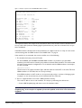
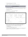
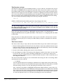
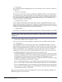
Troubleshooting
A guide to ISDN troubleshooting
Introduction
Ideally, setting up an ISDN connection is very much a straightforward process:
•
•
Connect the router to the ISDN network interface.
•
Send traffic.
Configure ISDN call definitions on the router. See Application Note 2033: Guidelines to Setting up
ISDN Calls on AR Routers (PDF: 202KB / 18 pages).
However, for one reason or another, there are occasions when the setup process is not as smooth
as it should be.
So if you have set up your router to communicate over ISDN, but the setup does not appear to be
working, here are some steps you can take to try and resolve the problem.
Step 1: Is the router communicating with the ISDN network at the
signalling level?
When the router is connected to the ISDN network, either by plugging it into an NT1 if the router
has an S/T interface, or by plugging it directly into the ISDN network if the router has a U interface,
it establishes a low-level connection to the network. Basically, the router and the network device
exchange a particular set of waveforms. When the router is satisfied that it has seen the correct
waveforms, it considers the low-level connection to be established, and the link is now ready to
send data frames.
There are two ways to determine whether or not the router considers that the connection is
established:
1. Look at the external LED marked "Active". This will be lit when the connection is established.
2. At the command prompt, enter the command:
show bri=n state
where n is the number of the BRI interface under consideration.
Interfaces are numbered from 0.
An example of the output of this command is shown in Figure 1.
Figure 1: Example output from the show bri=n state command
Manager ndl> sh bri=0 state
State for BRI instance 0:
Interface type .....
State ..............
Rx INFO ............
Tx INFO ............
Activate request ...
Activated ..........
Synchronised .......
Activation mode ....
Mode ...............
ISDN slots .........
D channel class ....
B1 enabled .........
B2 enabled .........
B1, B2 aggregated...
Rx multiframing ....
Transceiver mask ..
TE
Activated
INFO 4
INFO 3
no
yes
yes
normal
ISDN
B1, B2
high
no
no
no
no
56
The important item in this output is the second item, State. This must be shown as Activated. If it
has any other value (Inactive, Awaiting Signal, Synchronized, etc.) then the connection has not yet
been established.
If the BRI interface is Activated, then the problem lies at a higher level. Go to “Step 2: Is the router
communicating with the ISDN network at the LAPD level?” on page 4.
If the interface is not activated, the reason could be one of the following:
1. The interface has been put into NT mode.
On the AT-AR041 and AT-AR042 multi-BRI NSM modules it is possible to put the ISDN
interface(s) into NT mode so that they can emulate a network switch interface. This can be useful
for bench testing network configurations. To see which mode the ISDN interface is currently in,
use the command:
show bri=n state
The first item in the output, Interface Type, will have either the value NT or the value TE. If the
ISDN interface is in TE mode then it is set up correctly.
If the ISDN interface is in NT mode it is set up incorrectly, and it is a matter of changing a pair
of jumpers on the circuit board to put the interface back into TE mode.
2. There is a physical fault in the router's ISDN interface circuitry.
The router is able to test its own interface. The steps to performing the self-test are:
•
Create a BRI loopback plug and insert it into the interface socket.
If the BRI interface under consideration is on an ICM card, it is not necessary to use a
loopback plug, as the interface is capable of internal loopback, and so does not need external
loopback.
A guide to ISDN troubleshooting
2
•
At the command prompt, enter the command:
enable test int=brin
where n is the number of the BRI interface under consideration.
Interfaces are numbered from 0.
This initiates a 4-minute self-test.
•
Wait 4 minutes, until the router outputs a message to inform you that the self-test is complete.
Then enter the command:
show test
which will output the test results as shown in Figure 2.
Figure 2: Example output from the show test command
Manager NDL> sh test
Board
ID Bay Nick Name
Part Name
Rev
Serial number
---------------------------------------------------------------------------Base
47
3100
NIQ-3100
M2-0 9774202
IC Module 39
0 ICM-BRI1
EXP-0303
M1-2 8620690
Duration
Details
Interface State
Result
Type (minutes) Data( %OK ) Control
---------------------------------------------------------------------------eth0
no test
port0
port1
port2
port3
no
no
no
no
test
test
test
test
-
-
-
-
-
-
BRI0
complete good
4
good(100.0)
----------------------------------------------------------------------------
If the Result column shows the result to be good, then the BRI interface has no physical faults
(that the self-test can detect, anyway). If the result is anything other than good, then the
interface is faulty and you will need to contact your distributor regarding a repair.
•The cable connecting the router to the ISDN network or NTI is faulty.
Try a different cable.
•There is a fault in the ISDN network or the NT1.
If options 1, 2 and 3 do not show any faults on the router, then contact your ISDN network
provider and see if they can find the fault on their network.
A guide to ISDN troubleshooting
3
Step 2: Is the router communicating with the ISDN network at the
LAPD level?
Once the router has established a signalling connection with the network, it starts sending LAPD
packets. LAPD (Link Access Protocol - D channel) is a protocol whereby the router establishes a
logical connection with the ISDN switch. It is via this protocol that the router informs the switch of
its presence, and the switch allocates the router a connection ID. An LAPD connection has to be
established before the router can make or receive ISDN calls.
To see if an LAPD connection has been established, use the command:
show lapd=n
where n is the number of the BRI interface under consideration.
Interfaces are numbered from 0.
The output of this command will be as shown in Figure 3.
Figure 3: Example output from the show lapd=n command
Manager ndl> sh lapd=0
Interfaces:
ISDN
Type
TEI Mode
Debug
TEI
-------------------------------------------BRI0
TE
automatic
off
064
-------------------------------------------SAPs:
ISDN
SAPI
T200
T201
T202
T203
N200
N201
N202
k
-------------------------------------------------------------------BRI0
063 000010 000010 000020 000100 000003 000260 000003 001
000 000010 000010 000020 000100 000003 000260 000003 001
-------------------------------------------------------------------DLCs:
ISDN SAPI CES TEI State
V(S)
V(A) rxN(S)
V(R) rxN(R)
-------------------------------------------------------------------BRI0
063 000 127 bcast
000 000 127 bcast
001 064 ALIVE
0000
0000
0000
0000
0000
--------------------------------------------------------------------
The most important item to look at in this output table is the very last line. If an LAPD connection
has been established, then the entry in the State column in this line will be ALIVE. If the connection
has not been established, the state will be DEAD.
If the LAPD is alive, then the problem lies at a higher layer. Go to “Step 3: Are ISDN calls
connecting successfully?” on page 5.
If the LAPD is not alive, the reason could be one of the following:
1. The TEI mode has been set incorrectly.
On a Basic Rate interface, the TEI mode ought to be automatic, so that the router does not
mandate a TEI value to the switch, but will automatically accept whatever value is assigned by the
A guide to ISDN troubleshooting
4
switch. The TEI mode of the BRI interface is shown in the first line of output from the show lapd
command. If the value shown in the TEI Mode column is automatic, then the interface has been
set properly. If the value is shown as non-automatic, then the interface has not been set up
properly. Use the command:
set lapd=n mode=automatic
It may be necessary to set this in the router's config script, and reboot the router.
2. There is a problem in the ISDN network.
If the router is sending valid LAPD packets, and the switch is not responding correctly, then
LAPD will stay in the DEAD state. Contact your ISDN network provider and report a network
fault.
Step 3: Are ISDN calls connecting successfully?
If the router has an LAPD connection to the switch, then when an outgoing call is made from the
router, it will send call setup messages to the switch. If the switch believes that the packet is valid
and there are channels available in the ISDN network, it will forward it on to the router at the far
end of the link. The receiving router will then either accept or reject the call, depending on the
contents of the packet.
If the receiving router accepts the call setup request, the ISDN call will come open, and the routers
will endeavour to exchange data packets. If the call does not come open, then there will obviously
be no exchange of data.
In order to determine whether calls are coming open, use the command:
show isdn log
which will output a record of the last few ISDN calls, successful or otherwise, as shown in Figure 4.
Figure 4: Example output from the show isdn log command
Manager ndl>
sh isdn log
Call Name
Start Time
Duration Dir Number
Cause
----------------------------------------------------------------------------tdc
12-Dec-1997 11:18:51
CLEARED OUT 035439003
U16,chs
12-Dec-1997 11:19:03
CLEARED OUT 073333333
N1,ajpwlg
12-Dec-1997 11:19:36
0:01:01 OUT 044940190
U16,ajpwlg
12-Dec-1997 11:23:12
0:01:01 OUT 044940190
U16,abb
12-Dec-1997 11:23:33
0:00:49 OUT 093560114
U16,ajpwlg
12-Dec-1997 11:24:05
CLEARED OUT
ajpwlg
12-Dec-1997 11:24:25
0:01:02 OUT 044940190
U16,ajpwlg
12-Dec-1997 11:24:27
CLEARED OUT 044940190
N21,gc
12-Dec-1997 11:25:14
CLEARED OUT 3776569
N27,ppta
12-Dec-1997 11:25:38
CLEARED OUT 043842672
N17,to_boe
12-Dec-1997 11:26:13
CLEARED OUT 00441256376991
N18,pfricc
12-Dec-1997 11:26:38
CLEARED OUT 3432977
N17,----------------------------------------------------------------------------No ISDN logging port defined.
When it comes to diagnosing an ISDN connection, the two most important columns in this table
are Duration and Cause.
A guide to ISDN troubleshooting
5
The Duration column
The Duration column tells you immediately whether or not the call ever connected. If the entry in
this column is CLEARED, then the call never connected. If the entry in this column is a time, then
the call did actually connect at the ISDN level. The reason why you were unable to get data across
will be found at a higher protocol level (PPP or IP, IPX etc). Typically, if the duration of the call was
one or two seconds, then the call would have been closed due to a PPP negotiation failure. One of
the most common causes of PPP negotiation failure is due to PAP or CHAP authentication failing.
This can be quickly checked by looking in the router log, using the command:
show log
A PAP or CHAP authentication failure generates a log message of the form
01 01:16:06 5 PPP
AUTH
FAIL
ppp0: PAP authentication over isdn-dial1 failed
The log message appears on the router that is doing the authenticating, which may well be
the router at the other end of the link. The way to tell which router decided to close the call
is to check the Cause column.
If the call is being disconnected due to PAP/CHAP negotiation failure, see Technical Note 3:
Configuring PPP Authentication using PAP and CHAP for a full discussion on configuring PAP and CHAP
on the router.
If the call seems to be being disconnected for other reasons at the PPP or IP level, then it would
probably be necessary for you to contact your Allied Telesyn reseller or distributor for technical
assistance.
The Cause column
The Cause column tells you why a call was disconnected. Each entry in this column has three parts:
1. A letter indicating which end of the link took the call down. U (for User) indicates that the router
itself closed the call. N (for network) indicates the call was closed either by a switch in the ISDN
network, or by the router at the other end of the call.
2. A cause code number, indicating the reason for the call closure.
3. An extra diagnostic number. The meaning of this diagnostic number varies from one cause code
to the next. For most cause codes, this field is actually blank. It is necessary to have a good
working knowledge of ISDN and access to ISDN standards manuals in order to make any use of
these diagnostic numbers.
The cause code number can give you a lot of information about why your call is not working. Values
commonly seen for this code are:
•
16 - Normal
The call opened and was then closed by an indication from a higher layer protocol that it was
time to close the call. So, any successful call that passes data, and then is closed due to the PPP
idle timer timing out due to no more data being sent will have a cause code of 16.
Also, a call that is closed due to PAP/CHAP authentication failure will have a cause code of 16
because the call worked fine at the ISDN level, and was closed due to an indication from the PPP
layer. In this case, if the local router decided that the PAP/CHAP username/password it received
were invalid, then the letter preceding the cause code will be U; if the remote router rejected
the username/password sent to it, the letter proceeding the cause code will be N.
A guide to ISDN troubleshooting
6
•
17 - User busy
This is just like getting the engaged signal on a voice call. All you can do is wait for a while and
try again later.
•
18 - No user responding
There seems to be a device at the far end which has a LAPD connection to the switch but it is
not responding to the call setup messages. This may indicate that the device at the far end has
been set up to only make outgoing calls, or that it has a software or hardware fault that has put
it in a state whereby it is capable of maintaining a LAPD connection to the switch, but can't
actually responding to call setup requests.
•
27 - Destination out of order
You are calling a valid number, but the switch does not have a valid LAPD connection on the
channel corresponding to the number you are calling. This may mean that the device at the other
end has not been properly installed yet, or is switched off. Or it may indicate a fault in the wiring
between the switch and the site where that call is terminated.
•
1 - Invalid number
The number you are calling is not assigned to any connection. Check the number you are calling.
This cause code occurs if your router is connected to the centrex service, and you are calling
a number outside of the centrex extensions, but have not preceded it with the prefix for an
'outside line'.
•
34, 38, 44, 42 - ISDN network congestion or fault
If you receive these cause codes regularly, you should contact your ISDN network provider.
•
21 - Call rejected
This is probably the most commonly seen cause code on failed ISDN connections. It almost
always indicates a mistake in router configuration. This cause code occurs when the call setup
packet is successfully delivered to the router at the other end of the connection, but the router
refuses the call because it is not configured to accept the call. There can be are a number of
configuration errors that can result in a call being refused. Common ones to look out for are:
•
•
No ISDN call definitions have yet been created on the receiving router.
•
There is an ISDN call definition on the receiving router that will accept the incoming call, but
there is not yet a Layer 2 interface (PPP or Frame Relay) configured to use this call definition.
•
There is an ISDN call definition on the receiving router that will accept the incoming call, and
there is a Layer 2 interface configured over the call definition, but this particular call definition
is already taken by another incoming call.
The ISDN call definitions configured on the receiving router are set up to search for particular
strings in the subaddress, CLI or user-user fields in the call setup packet, but the sending router
is not putting the correct strings into the correct fields. For a full discussion of call
identification using fields of the call setup packet, see Application Note 2033: Guidelines to Setting
up ISDN Calls on AR Routers (PDF: 202 KB / 18 pages).
Once you have tracked down where the configuration error lies, and remedied the problem, the
ISDN calls ought to connect correctly.
A guide to ISDN troubleshooting
7
Other tips for testing ISDN connections
If pings won't bring up a call, try activating it manually.
Typically when setting up an ISDN connection, you'll configure an ISDN call definition, then
configure a dial-on-demand PPP interface over the call definition, and then assign an IP (or IPX,
AppleTalk) address to the PPP interface. Then, the normal first step to testing the setup is to try
pinging the device at the other end of the link. If there is no response to pings, you could go through
all three steps above to try and determine why its not working. However, you can possibly bypass
some of the process by trying to 'manually activate' the ISDN call, rather than trying to bring it up
using pings. This is a more direct approach to testing the ISDN connection, and can often give you
more insight into what is going on.
The command to activate an ISDN call is:
activate isdn call=call-name
This command informs the ISDN module to directly attempt a call setup. However, before the call
setup is attempted, the router checks whether there is a Layer 2 interface configured over the call,
and if so, whether that interface is currently active.
If there is no Layer 2 (PPP or FR) interface configured over the call, then you will receive the error
message:
Call has no user attached
If you receive this message, then check carefully the PPP or FR interface that you have configured
over the ISDN call. The commands show ppp or show fr will show which ISDN call the router
believes the Layer 2 interface to be configured over as shown in Figure 5.
Figure 5: Example output from the show ppp command
Manager ndl> sh ppp=4
Name
Enabled ifIndex Over
CP
State
----------------------------------------------------------------------------ppp4
YES
08
IPCP
CLOSED
isdn-ntdial
LCP
STARTING
-----------------------------------------------------------------------------
Check carefully that the name of the ISDN call reported by show ppp or show fr is exactly the
same as the name of the call you are trying to activate. Note that the call name is just the string that
appears after the "isdn-" in the Over column.
© 2004 Allied Telesyn International Corp. All rights reserved. Information in this document is subject to change without notice.
All company names, logos and product designs that are trademarks or registered trademarks are the property of their respective owners.
www.alliedtelesyn.com
C613-16030-00 REV A